


Services on Demand
Article
 English (pdf)
 Article in xml format
 Article references
Indicators

Related links
-
 Cited by Google
 -
 Similars in Google
Share

 Permalink
Journal of the Southern African Institute of Mining and Metallurgy
On-line version ISSN 2411-9717
Print version ISSN 2225-6253
J. S. Afr. Inst. Min. Metall. vol.115 n.4 Johannesburg Apr. 2015
STUDENT EDITION
Re-aligning the cutting sequence with general support work and drafting a support sequence at Simunye Shaft
K. Lombard
Faculty of Engineering, Built Environment and Information Technology, Department of Mining Engineering, University of Pretoria
SYNOPSIS
'Roof support awaiting time' (RSAT) is a term used at Goedehoop Colliery's Simunye Shaft to describe the potential production time lost due to the continuous miner (CM) standing idle waiting for roof support to catch up. Investigations revealed that in 2013, Simunye Shaft had approximately 1400 hours of RSAT, which suggests that the mine could have potentially produced an additional 280 000 t of coal. This project consisted of two parts. Firstly, the causes of the high RSAT and means to improve the situation were investigated. Secondly, as insisted by mine management, the CM cutting sequence was investigated as a possible cause of high RSAT. Machine-related challenges due to the roofbolter installing support too slowly, geological conditions (mostly hard roof conditions and slips), logistical challenges pertaining to the CM cutting sequence, man-related challenges related to operator fatigue, re-support, operator inexperience, and the absence of support targets were identified as main contributors to RSAT. Furthermore, results showed that the roofbolters in the sections at Simunye Shaft are slower than the CMs. A target of 28% reduction in RSAT was set. Experts from Kennametal and Fletcher were consulted to find solutions for the identified causes. In total, eight solutions for RSAT were identified, but the solution that contributed most significantly to reducing RSAT was to use hard roof drill bits as a standard product at Simunye Shaft. Calculations showed that by using hard roof drill bits, RSAT can be reduced by 43%, which is more than the specified 28% target.
The cutting sequences at Kriel, Greenside, and Simunye Shaft, together with three newly developed cutting sequences, were simulated using the UCMS (Underground Coal Mining Simulation) program. A re-aligning principle was incorporated into the newly developed cutting sequences to align the cutting sequences to general support work and to reduce RSAT. A decision matrix revealed that a cutting sequence in which boxing takes place in R3 (third road to the right of the belt road) and in which the realigning principle has been incorporated will be the best option for Simunye Shaft. The recommended cutting sequence will lead to a 5% increase in production.
Keywords: roof support awaiting time, CM cutting sequence, simulation, hard roof drill bits, support sequence.
Mine background and general information
Simunye Shaft is an Anglo Thermal Coal underground mining operation. The mine is situated approximately 41 km from Emalahleni, Mpumalanga Province. Simunye Shaft has five bord and pillar sections, four of which are continuous miner (CM)-shuttle car sections and one is a CM-FCT (flexible conveyor train) section. The No. 4 Seam is mined at an average seam height of approximately 3 m.
At Simunye Shaft, the floor, comprising largely sandstone or a sandstone/siltstone combination, is expected to be reasonably competent. The immediate roof, however, consists of an interlaminated unit of shale and siltstone and may present roof stability challenges. The roof encountered during mining varies from soft to hard, and hard roof conditions may result in support challenges (Mathetsa, 2013).
Project background
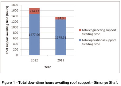
'Roof support awaiting time' (RSAT) is a term used by Goedehoop Colliery to describe the potential production time lost due to the CM standing idle waiting for roof support to catch up. There are two types of RSAT, namely operational RSAT and engineering RSAT.
Operational RSAT (Figure 1) is driven by operational processes e.g. the roofbolter falling behind the CM due to adverse geological conditions, damaged roofbolts, material shortage, cutting out of sequence (which may lead to logistical problems that will prevent the roofbolter from finishing support in time), etc. Engineering RSAT is potential production time lost due to roofbolter breakdowns. Support awaiting time has proven to be a major bottleneck in production at Simunye Shaft. As illustrated in Figure 1, support awaiting time amounted to 1700 and 1400 hours in 2012 and 2013 respectively. This means an additional 280 000 t could potentially have been produced in 2013. On average, almost 14% of available in-section production time was lost due to operational RSAT. The mine lost a potential R125 million in revenue, and although this was less than in 2012, it was still an enormous loss. The RSAT of the No. 4 Seam CM-shuttle car sections amounted to approximately 72% of the total RSAT, and therefore this project covers only No. 4 Seam CM-shuttle car sections at Simunye Shaft.
Support is a major component of the production process. If three faces are left unsupported (according to Anglo American Thermal Coal standards) the CM has to wait for support before production can commence. Therefore, to improve section productivity, it is vital to make the timeous installation of roofbolts a priority.
The question arises as to what may be the causes of high RSAT. It was the author's goal to identify the main causes of the high RSAT at Simunye Shaft and to suggest strategies that will make the timeous installation of roofbolts a priority.
Based on underground logbook data, the causes of RSAT can be divided into five main categories (Figure 2):
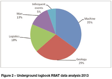
➤ Problems related to the roofbolter being too slow or on breakdown (machine problems)
➤ Geological conditions: hard roof conditions, conditions in which slips are encountered and in which oslo straps have to be installed
➤ Logistical challenges (when the roofbolter is blocking the CM) due to the cutting sequence not taking the interaction between the CM and roofbolter into account
➤ Man-related challenges - operators supporting too slowly or arriving late for work. Re-support and material shortage also fall into this category. Operators need to re-support when roofbolts are damaged during the roofbolting process or when the spacing between the roofbolts is inadequate
➤ Infrequent events, includes when support is updated, a temporary support jack has to be installed, and when the roofbolter has to wait for the LHD to complete sweeping.
As indicated in Figure 2, machine, geology, and logistical challenges are the main contributors to RSAT, contributing 82% of the problem.
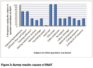
It should be noted that the logbook data was very incomplete and that more than half of the RSAT could not be accounted for. Only 190 data points out of total of 800 were used as a result. Owing to the incompleteness of the data, a survey was conducted among underground workers to obtain a better understanding of the causes of the high RSAT. Twelve surveys were completed (results depicted in Figure 3). The installation of oslo straps and hard roof conditions were identified as main causes of the high RSAT. Most of the shift bosses raised the concern of a lot of new inexperienced workers in their sections, and one shift boss mentioned that 60% of his operators were new and had not received sufficient on-the-job training from the retiring workers. Most of the workers mentioned that the CM is faster than the roofbolter and that this is the cause for the high RSAT. Engineering breakdowns were also mentioned as a problem, and may be attributed to the fact that maintenance on roofbolters is not seen as a big priority.
It is important to identify and investigate the main aspects that contribute to RSAT so that RSAT can be reduced. By taking the analysis in Figure 2 and the survey results in Figure 3 into consideration, the following will be investigated:
➤ Machine considerations - means by which to increase the speed of roofbolt installation. Slow roofbolting is the main contributor to RSAT
➤ Geological conditions (including hard roof conditions and slips) - this is the second highest contributor to RSAT
➤ Logistical issues - means by which to improve the CM cutting sequence
➤ Man-related challenges - operator fatigue as a contributor to RSAT
➤ Other challenges - re-support
➤ Operator inexperience
➤ The implementation of support targets (bolts installed per shift).
Engineering breakdowns will not be investigated, because these are machine-related and can be prevented only by means of a better maintenance plan (increase in maintenance time, maintenance staff, and more reliable equipment).
Investigating the engineering breakdowns of the roofbolter as a contributor to RSAT's is, however, suggested as a topic for further work. It should also be noted that purchasing new roofbolters (so that there are two roofbolters available per section) was eliminated as a solution, seeing that Simunye Shaft does not have the capital to purchase new roofbolters.
The high RSAT called into question the current CM cutting sequence, which was developed with a main focus on the CM. Will a new cutting sequence with a support approach improve RSAT? A deeper investigation into the cutting sequence currently employed at Simunye Shaft will be performed as the mine sees it as a priority to optimize its cutting sequence by re-aligning it to general support work and thereby reducing RSAT.
Objectives and methodology
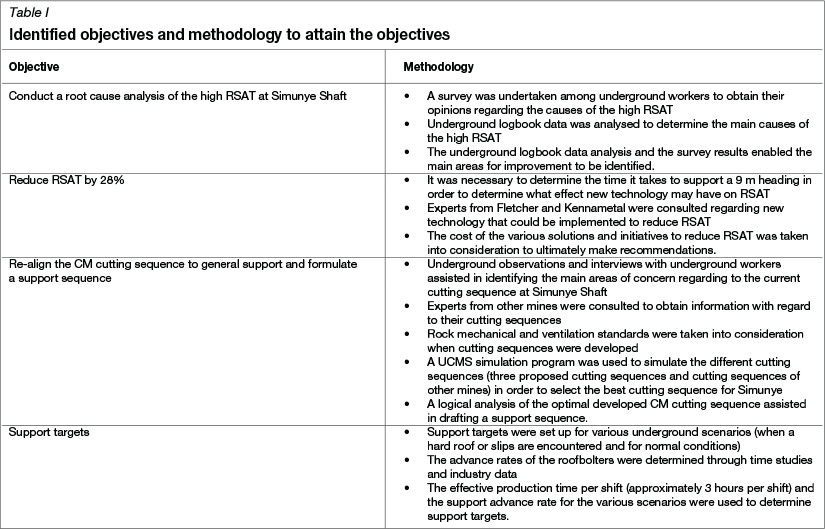
The objectives that were identified during the course of the project as well as the methodology used to meet the objectives are set out in Table I.
Literature survey
An extensive investigation into work that has already been done to reduce RSAT at underground coal mines, yielded only limited information. This may be attributed to the fact that, in general, underground data - for example the number of roofbolts installed and amount of drill steels used per shift - is not recorded in an organized or accurate manner. Therefore, the causes of the RSAT cannot be pinpointed easily. The analysis of underground logbook data in order to determine the causes of RSAT is a time-consuming process.
The literature study consisted of five parts. Firstly, a standard support sequence was described. This assisted in understanding the roof support process and provided a starting point from which improvements could be made. Secondly, the changes brought about in the support process when slips are encountered were described. Slips are one of the causes of RSAT - support spacing is reduced when a slip is encountered, which increases the time required for installing support. Thirdly, the main causes of RSAT at Kriel Colliery were investigated to strengthen the motivation for the study. Fourthly, solutions that may reduce RSAT were investigated. Finally, the cutting sequences employed at Simunye Shaft, Greenside Colliery and Kriel were described to illustrate where improvements in Simunye Shaft's cutting sequence could be made.
Standard roofbolt installation sequence
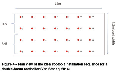
In Figure 4, the red dots indicate where roofbolts are installed, and the numbers indicate the sequence in which the roofbolts are installed (mining takes place from left to right in the figure). Looking in the direction of mining, support starts at the beginning of the heading at the far left-hand and far right-hand side simultaneously (two roofbolts are installed at the same time) and then proceeds to the inner left-hand and right-hand side. The same installation sequence is employed at Simunye Shaft.
Slips
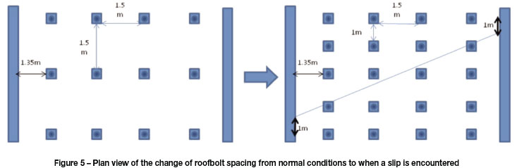
If slips are encountered at Simunye Shaft, the spacing between two consecutive lines of support is reduced from 1.5 m (normal conditions) to 1 m as illustrated in Figure 5. It should be noted that, in the figure, mining takes place from the bottom upward. If multiple slips are encountered, oslo straps need to be installed in addition to the reduced spacing.
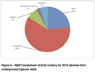
RSAT at Kriel Colliery
By analysing the RSAT at another colliery, the significance of the problem can be emphasized and the motivation for the study strengthened. Kriel Colliery had 1401 hours (almost exactly that of Simunye Shaft) of operational RSAT in 2012. This illustrates that other collieries have the same types of problems and a mind-shift is needed to overcome the problem - roof support needs to become a higher priority. Figure 6 illustrates the breakdown of the RSAT at Kriel Colliery for 2012. Machine-related challenges are documented as the highest contributor to RSAT, mainly due to the roofbolter being too slow. Logistical issues related to the CM cutting sequence are 10% lower than that of Simunye Shaft. It should, however, be noted that almost 64% of the data points in this analysis could not be used as they were recorded as 'n/a', or unaccounted for. It is clear that RSAT is not only a problem at Simunye Shaft, but also at the other collieries in South Africa. It is of great importance to solve this problem to ultimately enable collieries to increase their efficiencies.
Possible solutions
The oslo strap holder
According to Steyn (2013), a consultant at Fletcher, oslo strap holders (which are attached to the roofbolters at Greenside Colliery) have the potential to reduce the time to install an oslo strap by more than one minute. The oslo strap holder (Figure 7) assists the roofbolter operator to position the oslo strap (which normally takes a considerable amount of time) and in doing so increases safety significantly.

Standardizing the drill bits used at Simunye Shaft to hard roof drill bits
A hard roof decreases the penetration rate and bit life (bits will have to be changed more frequently). Both the reduction in penetration rate and the excessive replacement of drill bits lead to an increase in support time. Hard roof drill bits are available and are used by the mine for hard roof conditions. The hard roof drill bits should increase the life of a single drill bit and may increase the penetration rate.
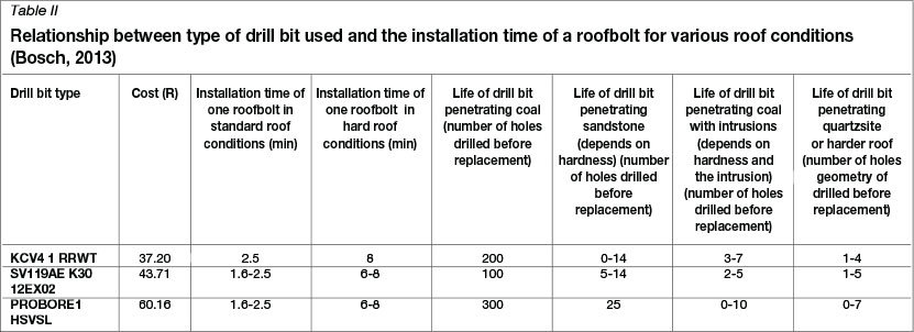
Table II contains information with regards to the penetration rates and costs of the different drill bits that can be supplied to Simunye Shaft and the different roof conditions encountered. The figures are estimated and may vary with operator skill, geology, and the consistency of adjusting the roofbolter's settings if roof conditions change.
The KCV4 1 RRWT (Table II) is the current drill bit employed at Simunye Shaft for normal roof conditions. If a hard roof is encountered, the SV119AE K3012EX02 drill bit (Table II) is used. The PROBORE1 HSVSL (not used at Simunye Shaft) has very good heat resistant properties, which increases drill bit life, but its high price makes it unsuitable for use as a standard product (Bosch, 2013). When used in hard roof conditions, the KCV4 1 RRWT drill bits (which are designed for normal roof conditions) and drill steel heat up rapidly and melt into the adapter. Removing the drill steel from the adapter can easily take 30-60 seconds (Bosch, 2013). By standardizing to hard roof drill bits, the installation time per roofbolt can be decreased by approximately 30 seconds (Table II). It should be noted that if KCV4 1 RRWT drill bits are used for hard roof conditions, the time to install a roofbolt may increase to 8 minutes (Table II).
The torque indicating system
According to Sinden (2013), the installation quality of a support system is directly related to the performance of the machinery used to install the bolts. Statistics shows that only 20% of all bolters have torques set within the correct Newton-metre range (200-350Nm). Sinden also mentions that the operator torques the roofbolt according to what he thinks or sees is right, and that that is the reason why common faults such as over-torque (flattened washers) and under-torque (loose washers) conditions occur. In the event of over-torque, the bond between the resin and bolt may be damaged, the washers may be deformed, the nuts may be rounded, and roofbolt threads may be damaged. Under-torque results in loose washers, incorrect mixing of resin, not breaking the shearing pin, and not flattening the torque indicator (Sinden, 2013).
The torque indicating system was designed to avoid substandard torque (which may require re-support of roof bolts). The torque indicating light is clearly visible during operation and ensures accurate bolting torque. The operator, miner, and technician can also see when the torque of the roofbolter drill chuck is not optimal (Sinden, 2013).
The torque indicating system has a data logging feature that can capture data such as the torque, time, date, the number of roofbolts installed, spinning time of resin, and holding time before a roofbolt reaches torque (to help estimate accurate roofbolt and resin usage). The torque indicating system will therefore result in the better management of roofbolting crews, as managers will know how the crew has performed (number of bolts installed per shift). The system will also reduce RSAT resulting from resupport being required. The torque indicating system is a new product on the market and its advantages can be summarized as follows (Sinden, 2013):
➤ The torque indicating light is highly visible
➤ If the system fails to operate correctly, the operator can identify and report immediately
➤ Accurate torque on every roofbolt is ensured
➤ The system helps to overcome human errors and faulty hydraulic systems
➤ The system is cost-effective
➤ It reduces machine working hours
➤ Time on re-installation is saved
➤ Labour and re-installation costs are reduced
➤ The system eliminates the re-occurrence of over- and under-torque.
The MCS roofbolter monitoring system
MCS offers two options for data recovery (operating time, tramming time, downtime, and number of roofbolts installed) with the roofbolter system. The first system, which is currently in use at Anglo Thermal Coal sites, is a flash card system. The operator is responsible for inserting the flash card at the beginning of the shift and returning it to the control room for processing at the end of shift. The second is a Wi-Fi system, where the onboard data collection unit communicates to the node which is integrated into the mine's communication backbone, allowing file transfer to the control room. This can be done in two ways - firstly, by means of two nodes, and secondly by means four nodes. The advantage of installing more nodes is increased coverage. The MCS system and torque indicating system are similar. The biggest difference between the two systems is cost - the torque indicating system is more cost-efficient.
The auto-bolter
According to Steyn (2013) a roofbolter operator handles approximately 1.5 t of steel per shift and makes approximately 14 lever movements per roofbolt installed. The operation of a roofbolter involves strenuous tasks, and the time to install a roofbolt can increase from 2.5 minutes at the beginning of a shift to approximately 10 minutes at the end of a shift as a result of operator fatigue. The weighted average time to install a bolt is 6.75 minutes. This was calculated by increasing the time to install a bolt linearly every 30 minutes over a 3 hour (effective operating time) period.
The autobolter technology, which is currently being implemented at Greenside Colliery, may eliminate this problem. The autobolter has the following advantages (Steyn, 2010):
Safety:
➤ Reduces the number of accidents related to the handling of roofbolts and the operation of the roofbolter
➤ Moves the operator to a safer position.
Productivity:
➤ Reduces operator fatigue
➤ Ensures the consistent installation of bolts.
Reliability:
➤ Removes the human factor
➤ Records roof mapping information
➤ All bolts are installed to the same standards and procedures.
Engineering:
➤ The autobolter has various pressure settings for feed and rotation
➤ It is difficult to tamper with the machine setup
➤ Pressures and sensors are displayed on a display screen.
The autobolter ensures that each bolt is installed to the correct standard (re-support is eliminated) and operator fatigue is eliminated completely as the roofbolter is remote-controlled and the operators do not have to handle the heavy roofbolts. However, the cost of the autobolter - approximately R14 million -eliminates it as a solution as the mine's budget does not cater for the purchase of new roofbolters.
Current cutting sequence employed at Simunye Shaft
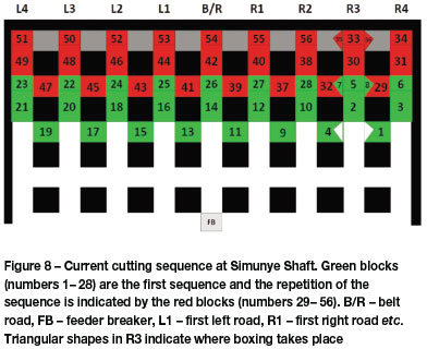
It is necessary to analyse and evaluate the effectiveness of the cutting sequence currently employed at Simunye Shaft, as it was developed with a main focus on the CM (a support sequence was never developed). A support sequence can be described as the sequence in which the roofbolter supports the headings and splits cut by the CM. The current support sequence employed at Simunye consists of the roofbolter following the CM sequentially as far as possible. The shortcomings of the cutting sequence, with regard to support have to be identified in order to identify solutions to the problem of RSAT. The current cutting sequence employed at Simunye Shaft is illustrated in Figure 8. The green blocks (numbers 1-28) are the first sequence and the repetition of the sequence is indicated by the red blocks (numbers 29-56). The belt road (B/R), the first left road (L1) to the fourth left road (L4) and the first right road (R1) to the fourth right road (R4) are indicated. The triangular shapes in the R3 indicate where boxing takes place. Boxing is when a triangular shape is cut into the coal face to make it easier for the CM to manoeuvre when it is cutting cuts number 4 and 1 of each sequence. The feeder breaker (FB) is also indicated in the figure. Simunye Shaft's cutting sequence ends in R2, which is close to where the following cutting sequence starts. Boxing takes place in R3 so that through ventilation is established as quickly as possible.
Cutting sequences at other collieries
By investigating different cutting sequences employed by other mines (with more or less the same pillar sizes as Simunye Shaft), an optimal cutting sequence for Simunye Shaft can be developed.
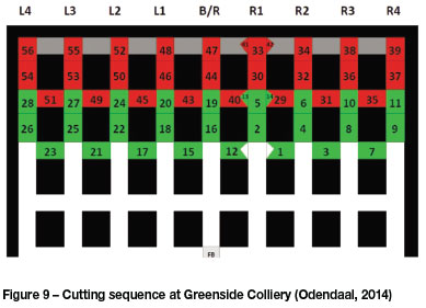
Greenside
Figure 9 illustrates the cutting sequence employed at Greenside Colliery. Boxing takes place in R1 and the cutting sequence ends at the far left-hand side.
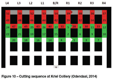
Kriel
Figure 10 illustrates the cutting sequence followed at Kriel. Boxing takes place in R1 and the cutting sequence ends close to where the following cutting sequence starts.
In summary the following concepts can be incorporated into a cutting sequence:
➤ To box in R1 (reduce cable handling efforts and time)
➤ To box in R3 (establish through ventilation as soon as possible)
➤ To end the cutting sequence at the far left-hand side
➤ To end the cutting sequence close to where the next cutting sequence will start.
A combination of these concepts can be used to develop various cutting sequences for Simunye Shaft. The developed cutting sequences can then be simulated to determine which one would be the best for Simunye Shaft.
Developing an optimum cutting sequence
According to Shaw (2013), the following factors need to be taken into consideration when a cutting sequence is developed:
➤ The tramming and cable handling of the CM must be minimized
➤ Through ventilation must be established as soon as possible
➤ The roofbolter should not be in the way of the CM
➤ The tramming routes for all three shuttle cars should be optimized.
Hirschi (2012) conducted a study on Identifying Optimal Mining Sequences for Continuous Miners. In this study he mentions the following guiding policies and practices when developing a cutting sequence:
➤ Mine crosscuts should be in the direction of ventilation airflow
➤ A buffer should be maintained between the continuous miner and roofbolter.
Rock mechanical and ventilation standards also need to be taken into account. In terms of rock mechanical standards, not more than three faces may be left unsupported. If three faces are leff unsupported, the CM has to wait for support to catch up. The most important ventilation standard that needs to be taken into consideration is that an air speed of 1 m/s needs to be maintained in the last through road.
The UCMS simulation program
UCMS can be used to simulate cutting sequences. By changing input variables such as shift length, pillar sizes, probability of equipment breakdown, speed of the CM, and speed of the roofbolter, production rates and tramming time values can be obtained. This program was used to simulate the cutting sequences used at Kriel, Greenside, Simunye Shaft, and other developed cutting sequences.
Results
The results of the investigation are presented under the following topics:
➤ Time study on supporting a 9 m heading at Simunye Shaft. Calculations that follow will be based on this time study
➤ The effect of geological features on the time to support a 9 m heading. Both the time study and the effect of geological features on support time will be used to set up support targets
➤ A comparison of the advance rates of the CM and the roofbolter. This will help to determine whether the problem (of RSAT) lies with the roofbolting process
➤ The effect of implementing hard roof drill bits as a standard product
➤ Improving the cutting sequence currently employed at Simunye Shaft. Two developed cutting sequences and Greenside and Kriel's cutting sequences are simulated, and the performance of the four cutting sequences evaluated. A third cutting sequence is developed to improve on the results of the first four cutting sequences.
Time study
The time it takes to install a line of support is required to determine whether the roofbolter is too slow and where improvements can be made. If the time taken to install a line of support is known, RSAT logbook data can be used to quantify the benefits of various systems that can be used to reduce RSAT. A summary of a time study, conducted by Van der Merwe (2012), is set out in Table IV. The roofbolt installation sequence, illustrated in Figure 4, was used. The time study was carried out in Ubhejane section at Simunye Shaft. The bolting took place in normal roof conditions.
A few terms need to be understood to interpret the time study correctly. Total time per row can be described as the time from when the TRS (temporary roof support) is up until just before the TRS is lowered. Table III summarizes the average time it takes to install a roofbolt on each side (LHS or RHS) as well as the total time to support a 9 m heading and the relocation time of the roofbolter. Relocation time is the time from when the roofbolter starts moving to the next heading to the time that the TRS of the roofbolter is up at the new heading, and repositioning time is the time to reposition the bolter to the next hole that needs to be drilled and bolted. Repositioning time also includes the time to lift and lower the TRS.
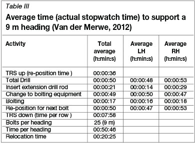
The average time to insert an extension drill rod is usually around 14-29 seconds (Table III). It was found that the time to insert an extension rod can be extended by almost 2 minutes if a drill bit has to be changed. Drill bit changes can therefore have a major impact on the time to install a line of support.
The changeover to bolting equipment usually takes 49 seconds (Table III), but during the time study it was found that if resin stock runs out it can add approximately 1 minute to the time. Material shortage or poor planning can therefore also contribute to a slower installation time.
The time to support a 9 m heading was determined to be approximately 50 minutes (Table III). Therefore, if a support target has to be set for normal conditions, a time of 50 minutes can be allocated to supporting a 9 m heading.
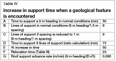
The effect of geological features on support time
If hard roof conditions or slips are encountered, support spacing is reduced, as described in the literature survey. This will result in an increase in support time due to the fact that more roofbolts will have to be installed. The increase in time needs to be established so that a realistic support target can be set for situations when such features are encountered.
As indicated in Table IV, the time to support a 9 m heading can increase from approximately 50 minutes in normal conditions (Table III) to approximately 75 minutes when a feature is encountered.
Performance of CM vs. roofbolter
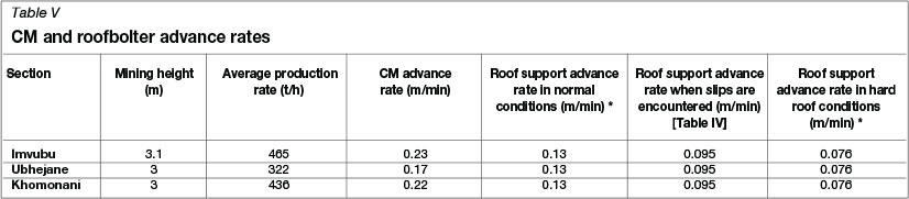
It is necessary to determine whether the CM or roofbolter advances faster, as this will indicate where the problem of RSAT lies and where improvements can be made. Table V indicates that the CM is faster than the roofbolter in all possible scenarios. The roofbolter can therefore not keep up with the CM in normal conditions. This is a contributing factor to the high RSAT. If the roofbolter advance rate is increased, RSAT may be reduced.
It should be noted that the relocation time (20 minutes) of the roofbolters was taken into account to determine the advance rate. In this report, the advance rate of the roofbolters will be improved to increase the CM advance rate (which already has RSAT intrinsic to it) and reduce RSAT. The increase in the average roof support advance rate will contribute directly to the increase in production.
Solutions to RSAT
Eight solutions to the challenge of RSAT were identified, but the most significant solution was to implement hard roof drill bits as a standard product at Simunye Shaft. Only this solution and the use of support targets are discussed in this report.
If normal KCV4 1 RRWT drill bits are replaced with hard roof SV119AE K3012EX02 drill bits (Table II), the life of the drill bits will increase as well as the roofbolt installation rate. Since the roofbolters at Simunye Shaft are slower than the CMs, the increase in installation rate can contribute directly to reducing RSAT. The hard roof drill bits will prevent operators from continuing to support using KCV4 1 RRWT drill bits in hard roof conditions while they wait for the hard roof drill bits to arrive. Using normal drill bits in hard roof conditions may cause the drill steel and drill bit to expand and become stuck in the adapter, which can result in time wastage.
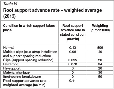
To determine the benefit of standardizing on hard roof drill bits, the average roof support advance rate has to be determined. For this it is necessary to take all the factors that can reduce the speed of support into account. These include:
➤ The installation of oslo straps
➤ The reduction in support spacing when slips are encountered
➤ Support in hard roof conditions
➤ Re-support
➤ Material shortage
➤ Engineering breakdowns.
The support advance rate under the conditions specified needs to be determined in order to ultimately calculate the weighted average support advance rate throughout the year (Table VI). The weightings (indicating the ranking of each condition) of the respective support advance rates were estimated from underground logbook data. The weighted average roof support advance rate was calculated to be 0.15 m/min.
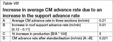
When hard roof drill bits are implemented as a standard product, the time to install a roofbolt can be reduced by 30 seconds (Table II). This means that the time to install a line of support can be reduced by one minute. A new support advance rate for each condition can be calculated. The new weighted average support advance rate (Table VII) can be determined by allocating the same weights (as in Table VII) to the respective advance rates.
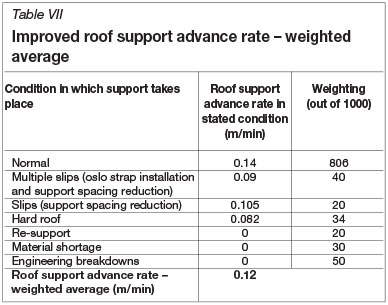
The increase in the support advance rate can be added directly to the CM advance rate, as the CM advance rate already includes the effect of RSAT. The average CM advance rate for Imvubu, Khomonani, and Ubhejane will increase to 0.221 (Table VIII), which is a 5% improvement in productivity.
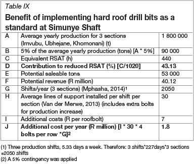
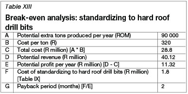
As indicated in Table IX, an additional 53 000 t of coal could have been produced in 2013, which is equivalent to 440 hours of RSAT. The result is a 43.13% reduction in RSAT. The additional cost per year if hard roof drill bits are implemented as a standard product at Simunye Shaft (for three sections) will amount to R1.8 million. The data in Table IX shows the additional roofbolts that will have to be installed if production is increased annually by 53 000 t for the three sections.
Support targets
To increase awareness of the importance of the timeous installation of roofbolts, support targets can be set. Metre targets for the CMs are always visible in the sections and help to formulate goal-orientated tasks for crews underground. The same effect can be created by setting support targets.
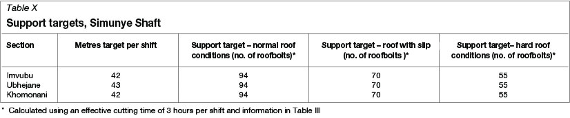
Table X indicates support targets for the No. 4 Seam sections at Simunye Shaft. The different conditions that may arise during roofbolting have to be considered when the targets are set. Therefore, targets for normal conditions, hard roof conditions, and conditions where slips are encountered are indicated in Table X. No cost is associated with this solution.
Cutting sequence development
The support challenges arising from the cutting sequence employed at Simunye Shaft can be summarized as follows:
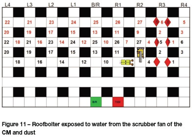
➤ While the CM is cutting cut number 9 (Figure 11), the roofbolter will be supporting cut number 8 from the left-hand side. This means the roofbolter will be working against ventilation. Workers (roofbolter operators) will be exposed to a lot of dust from the CM and water from the scrubber fan on the CM. This is repeated when the CM cuts numbers 11, 13, 15, 17, and 19. This scenario is illustrated in Figure 11
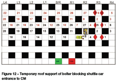
➤ When the roofbolter is supporting cut number 8 from the left-hand side, shuttle cars will be moving in R2 towards the CM. The temporary roof support of the roofbolter may not be able to reach the end of the split that needs to be supported or may block the shuttle cars that are approaching the CM. This scenario is illustrated in Figure 12.
In response to the challenges presented by the current cutting sequence, the re-aligning principle was developed. The re-aligning principle refers to aligning the CM cutting sequence with general support work. The concept is explained in Figures 13 and 14. In Figure 13, cuts number 8 and 9 create the challenges. In Figure 14, where the cutting sequence is aligned with support, there is a buffer between the CM and roofbolter. Consecutive cuts (numbers 8 and 9, 10 and 11, 12 and 13, etc.) are further apart. This results in the following advantages:
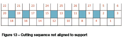
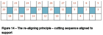
➤ Safer condition, because the roofbolter and CM will be further apart (lower risk of collision) and the roofbolter will not have to work against ventilation
➤ The roofbolter operators will not be exposed to dust and water from the CM
➤ The CM will not obstruct the path of the roofbolter and RSAT will be reduced.
The following cutting sequences were developed for simulation.
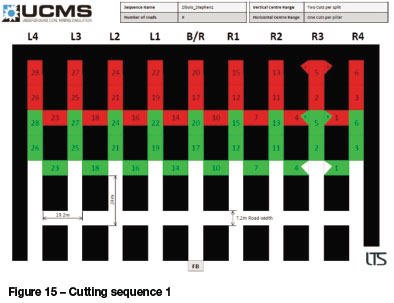
Cutting sequence 1
As illustrated in Figure 15, boxing takes place in R3 and the cutting sequence ends at the far left-hand side (a lot of tramming time is expected). The re-aligning principle was incorporated into the cutting sequence.
Cutting sequence 2
As illustrated in Figure 16, boxing takes place in R1 and the cutting sequence ends at the far left-hand side (less tramming time than cutting sequence 2 is expected). The realigning principle has been incorporated into the cutting sequence.
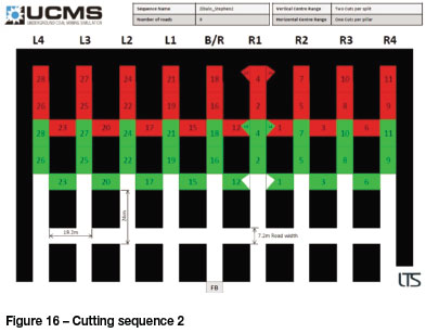
It should be noted that both these cutting sequences were approved by the ventilation department as well as the rock engineer at Goedehoop Colliery.
Simulation results
In total five cutting sequences were simulated:
➤ Cutting sequence 1
➤ Cutting sequence 2
➤ Kriel's cutting sequence
➤ Goedehoop's cutting sequence (the cutting sequence employed at Simunye Shaft)
➤ Greenside's cutting sequence.
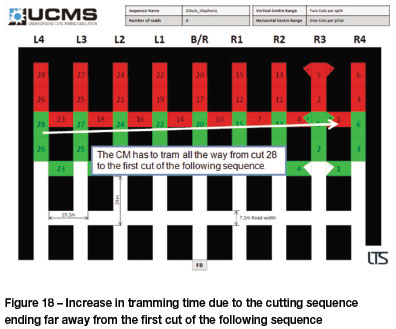
Figure 17 illustrates that cutting sequence 1 had the highest tramming time. It can therefore be confirmed that the greater the distance from the last cut of the sequence to the first cut of the following sequence, the greater the tramming time. Goedehoop's cutting sequence, which is the cutting sequence employed at Simunye Shaft, had the lowest tramming time. This may be because of the following reasons:
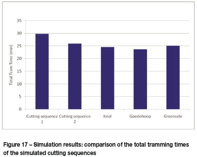
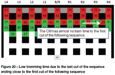
➤ Goedehoop's cutting sequence ends close to the first cut of the following sequence (Figure 18 shows the opposite scenario - a sequence ending far from the first cut of the following sequence)
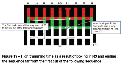
➤ When boxing takes place in R1 tramming time is added, because the CM has to move all the way from R4 (cut number 11) to R1 (cut number 12), as illustrated in Figure 19, to continue the sequence. This additional tramming time is eliminated if boxing takes place in R3 (Figure 20).
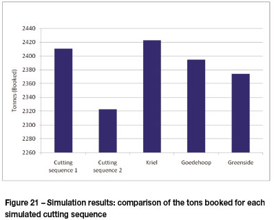
Kriel's cutting sequence came out top in the comparison of tons booked (Figure 21). A cutting sequence that incorporates the re-aligning principle and has a high enough production output still needs to be developed, as neither cutting sequence 1 nor cutting sequence 2 resulted in a better production output performance than Kriel.
A third cutting sequence was therefore developed to improve on the results obtained, combining all the concepts that resulted in the highest production and lowest tramming time.
Cutting sequence 3:
As illustrated in Figure 22, boxing takes place in R3 (through ventilation will be established soon) and the cutting sequence ends close to the start of the following cutting sequence. It can be seen that the re-aligning principle was incorporated into the cutting sequence.

This cutting sequence was approved by the ventilation department as well as the rock engineer at Goedehoop colliery.
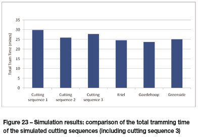
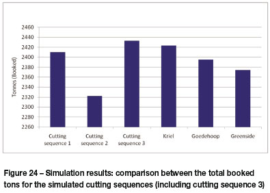
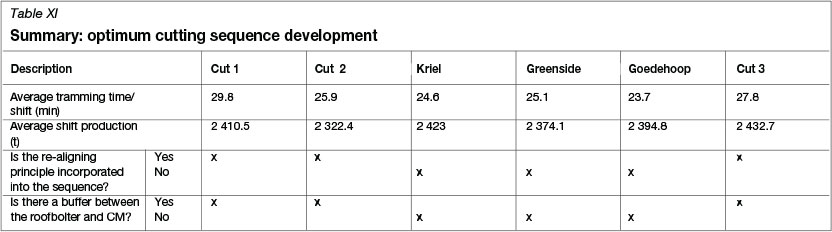
Figures 23 and 24 illustrate the simulation results. Cutting sequence 3 has a lower tramming time than cutting sequence 1 and average shift production is greater than all the other cutting sequences. Cutting sequence 3 had a 5% greater average shift production than the current cutting sequence employed at Simunye Shaft. This means the mine can potentially earn an additional R40 million in revenue per year.
With any of the cutting sequences that incorporate the realigning principle, the support sequence will be exactly the same as the cutting sequence of the CM, as the roofbolter will be following the CM sequentially.
The results relating to the cutting sequence development and simulation are summarized in Table XI.
Analysis and evaluation of results
In this section, the economic viability of the identified solutions are discussed, the simulation results analysed, and the optimum cutting sequence for Simunye Shaft identified by means of a decision matrix.
Economic viability of solutions to RSAT
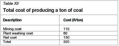
The costs of mining a ton of coal is set out in Table XII.
Standardizing the drill bits used at Simunye Shaft to hard roof drill bits
The break-even analysis (Table XIII) shows that the cost of the hard roof drill bits will be recovered in only 2 months. It should, however, be noted that the cost will be incurred annually. The capital outlay for the hard roof drill bits is low and this is therefore a viable option to implement.
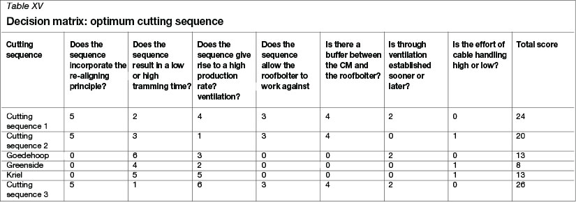
Optimum cutting sequence
In order to select the optimum cutting sequence, a decision matrix was set up. The cutting sequences are evaluated against seven criteria, namely:
➤ Does the sequence incorporate the re-aligning principle?
➤ Does the sequence result in a low or high tramming time?
➤ Does the sequence give rise to a high production rate?
➤ Does the sequence allow the roofbolter to work against ventilation?
➤ Is there a buffer between the CM and roofbolter?
➤ Is through ventilation established sooner or later?
➤ Is the effort of cable handling high or low?
The cutting sequence with the highest score will be recommended. The means of rating the cutting sequences is described to illustrate how the decision matrix was put together.
Does the cutting sequence incorporate the re-aligning principle?
Seeing that the re-aligning principle increases safety and will help reduce RSAT, a high weight has to be attached to it in this selection phase. If the cutting sequence incorporates the re-aligning principle, a score of 5 is allocated, and if not, a 0 is allocated.
Does the sequence result in a high or low tramming time?
Excessive tramming time is inefficient. The higher the tramming time, the lower the potential production. Six cutting sequences were simulated and therefore the sequence with the lowest tramming time is awarded a score of 6 and the sequence with the highest tramming time a 1.
Does the sequence give rise to a high production rate?
Production is directly related to profit. A score of 6 is awarded to the cutting sequence with the highest production output and a 1 to the sequence with the lowest.
Does the sequence allow the roofbolter to work against ventilation?
Working against ventilation is not good practice and worker safety is enhanced if the roofbolter does not work against ventilation. If the cutting sequence allows the roofbolter to work against ventilation a score of 0 is allocated to the cutting sequence, and if not a 3 is allocated.
Is there a buffer between the CM and the roofbolter?
A buffer between the CM and roofbolter will increase safety due to the fact that roofbolter operators will not be exposed to the dust from the CM and water from the scrubber fan of the CM. If a buffer between the CM and roof bolter is maintained, a score of 4 is allocated to the cutting sequence, and if not, a 0 is allocated.
Is through ventilation established sooner or later?
If through ventilation is established at the start of the sequence, ventilation needs will be met in a more effective manner. If through ventilation is established later, additional fans will have to be installed to maintain an air speed of 1 m/s in the LTR. If through ventilation is established sooner rather than later a score of 2 is allocated to the cutting sequence, and if not, a 0 is allocated.
Is the effort of cable handling high or low?
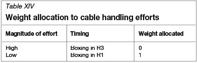
If cable handling requires less effort, fewer problems can arise to reduce production time. Worker morale will also improve. Cable handling efforts can be divided into categories as indicated in Table XIV. When boxing takes place in R3 the cable has to be suspended all the way to R3 from R1 (where the transformers are), and when the sequence moves towards R1 again, cable handling is doubled. However, if boxing takes place in R1 (where the transformers are) a lot of cable handling effort is eliminated, and flexibility is increased.
The cutting sequence with the highest score is sequence 3 (Table XV). This cutting sequence will ensure safer working conditions, increase production, and reduce RSAT.
Conclusion
In completing a root cause analysis of the high RSAT at Simunye Shaft, underground logbook data was analysed and underground workers were interviewed. Seven main contributors to RSAT were identified: machine-related challenges relating to the roofbolter installing support too slowly (the greatest contributor to RSAT), geological conditions (mostly hard roof conditions and slips), logistical challenges pertaining to the CM cutting sequence, man-related challenges (operator fatigue), re-support, operator inexperience, and the absence of support targets.
A 28% reduction in RSAT was set as the target. The use of hard roof drill bits as a standard at Simunye Shaft was identifiedas the best method to address the root cause of high RSAT (slow roofbolt installation). By implementing this solution, RSAT can be reduced by 43.13%, which is more than the 28% target. The total cost of implementing the solution will be R1.8 million per year, with a maximum payback period of 2 months. Simunye Shaft will potentially increase its revenue by R40 million by implementing this solution.
Logistical issues with regards to the CM cutting sequence were also identified as a cause of RSAT, and were thoroughly investigated as suggested by mine management at Simunye Shaft. Challenges with regard to the shaft's cutting sequence (that may lead to RSAT) were identified and the cutting sequences of Kriel and Greenside Colliery were analysed to improve the situation. A re-aligning principle that increases the buffer between the CM and roofbolter and prevents the roofbolter from working against ventilation, was developed. Three cutting sequences incorporating the re-aligning principle were developed and simulated together with the current cutting sequence of Simunye Shaft, Kriel, and Greenside Colliery. A trade-off study revealed that cutting sequence 3 had the most promising outcome, and although the effect on RSAT could not be quantified, it was verified that by implementing this cutting sequence Simunye Shaft could increase production by 5%. The support sequence for cutting sequence 3 is equivalent to the cutting sequence itself - the roofbolter can follow the CM sequentially.
Support targets were set up by using the calculated roofbolter advance rate in the various scenarios (hard roof and normal conditions, and when slips are encountered). The advance rate was then multiplied by the effective production time per shift. Findings showed that on average 94 roof bolts have to be installed per shift in normal conditions, 70 bolts when slips are encountered, and 55 when hard roof conditions are encountered. Targets for three scenarios were set, ensuring that the targets are fair and do not demoralise the work force.
Recommendations
It is recommended that Simunye Shaft should adopt hard roof drill bits as standard and that support targets for each shift be set. It is also recommended that cutting sequence 3 should be implemented.
Suggestions for further work
The following topics are suggested for further work:
➤ An investigation into reducing engineering-related RSAT
➤ An in-depth study of the cable handling logistics surrounding the implementation of cutting sequence 3 in this study
➤ A study on optimizing logbook data recordings, which will avoid inaccurate data recording
➤ An in-depth study pertaining to operator fatigue experienced by a roofbolter operators
➤ Quantifying the effect of changing operators mid-shift, and setting support targets, on RSAT
➤ A feasibility study on introducing an auto-bolter into sections at Simunye Shaft
➤ An investigation into change management aspects that need to be taken into account when a new cutting sequence is to be implemented at a colliery.
Acknowledgements
I would like to thank L.M. Mphasha, my mentor at the mine, and J.A. Maritz, my supervisor at the University of Pretoria, for their guidance and support.
References
Bosch, C. 2013. Personal communication. [ Links ]
Hirschi, J.C. 2012. A Dynamic Programming Approach to Identifying Optimal Mining Sequences for Continuous Miner Coal Production Systems. Dissertation. Southern Illinois University Carbondale. [ Links ]
Mphasha, L.M. 2014. Personal communication. [ Links ]
Mathetsa, S. 2013. Personal communication. [ Links ]
MCS. 2013. MCS Roof Bolter Monitoring Proposal for Goedehoop Colliery. Witbank: MCS. [ Links ]
Odendaal, A. 2014. Personal communication. [ Links ]
Sinden, J. 2013. Consultant: Fish Eagle Mining Solutions, Personal communication. [ Links ]
Steyn, J. 2010. Introducing the Fletcher Twin Boom, Automated Roof Bolter. Witbank: J.H. Fletcher & Co. [ Links ]
Shaw, E. 2013. Mining Engineer: Khutala Colliery, Personal communication. [ Links ]
Steyn, J. 2013a. Material Handling. J.H. Fletcher & Co., Witbank. [ Links ]
Steyn, J. 2013b. Personal communication. [ Links ]
Van der Merwe, B. 2014. Personal communication. [ Links ]
Van der Merwe, B. 2013. Personal communication. [ Links ]
Van der Merwe, B. 2012. Simunye Shaft Ubhejane section - 9m heading. Witbank: MCS [ Links ]
Van Staden, M. 2013. Department of Mining Engineering - Underground Coal Mining Methods. University of Pretoria [ Links ]
The work presented in this paper was carried out as partial fulfilment for the degree BEng (Mining Engineering)

