


Services on Demand
Article
 English (pdf)
 Article in xml format
 Article references
Indicators

Related links
-
 Cited by Google
 -
 Similars in Google
Share

 Permalink
Journal of the Southern African Institute of Mining and Metallurgy
On-line version ISSN 2411-9717
Print version ISSN 2225-6253
J. S. Afr. Inst. Min. Metall. vol.115 n.3 Johannesburg Mar. 2015
GENERAL PAPERS
Chemical wear analysis of a tap-hole on a SiMn production furnace
J.D. SteenkampI, II; P.C. PistoriusI, III; M. TangstadIV
IUniversity of Pretoria
IIMintek, Randburg
IIICarnegie Mellon University
IVNorwegian University of Science and Technology
SYNOPSIS
In April 2013 a 48 MVA submerged arc furnace producing silicomanganese was excavated in South Africa. Since the high shell temperatures recorded in the tap-hole area resulted in the furnace being switched out for relining, the tap-hole area was excavated systematically. A refractory wear profile of the tap-hole area with affected hearth and sidewall refractory was obtained in elevation. The carbon ramming paste in front of, above, and below the tap-hole was worn, as was the SiC with which the tap-hole was built. A clay mushroom formed but was detached from the refractories. Thermodynamic and mass-transfer calculations were conducted to quantify the potential for wear by chemical reaction between refractory and slag and refractory and metal in the tap-hole area. It was found that chemical reaction between refractory and slag or metal could offer only a partial explanation for the wear observed; erosion is expected to contribute significantly to wear.
Keywords: excavation, dig-out, post-mortem, submerged arc furnace, silicomanganese, refractory, tap-hole, thermodynamics, FACTSage, mass transfer
Introduction
Silicomanganese (SiMn) is an alloy used in steelmaking to provide both Si and Mn additions at low carbon contents. In South Africa, SiMn is produced in three-phase alternating current (AC) submerged arc furnaces (SAFs) by carbothermic reduction of manganese ores in the form of lump, sinter, and briquettes (Steenkamp and Basson, 2013). In a SAF the electrode tips are submerged in a porous charge mix, with electrical energy being liberated by micro-arcing to a slag-rich coke bed floating on top of a molten metal bath (Olsen and Tangstad, 2004; Matyas et al., 1993). Typical power ratings for SAFs producing SiMn are 15-40 MVA; such furnaces produce 80-220 t of metal per day (Olsen and Tangstad, 2004). The furnaces are circular, with an external diameter of 11.6 m and height of 6.2 m being typical of a 40 MVA furnace (Brun, 1982).
The initial report on the tap-hole wear profile and thermodynamic calculations conducted to understand the potential for chemical reaction as wear mechanism in the tap-hole area was presented at the SAIMM Furnace Tapping Conference (Steenkamp et al., 2014). The paper presented here expands on the previous work by including mass-transfer calculations to estimate the possible extent of wear by chemical reaction.
Background
The SAF under investigation was of circular design with an open roof and outer diameter of 12 m. The furnace containment system consisted of a refractory lining installed in a steel shell. The refractory design from the hearth to the top of the sidewall is indicated in Figure 1. The compositions of the refractory materials of interest are presented in Table 1.
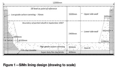
In the hearth, fireclay was cast onto the steel shell to level the floor. The fireclay is an aluminosilicate aggregate with alumina cement binder. Five layers of super-duty fireclay bricks were installed as back lining, with high-grade carbon ramming as working lining. In the lower sidewall, a single layer of super-duty fireclay brick was installed as back lining with high-grade carbon ramming as working lining. As safety lining, a low-grade carbon ramming was emplaced between the steel shell and the back lining. In the upper sidewall, the lining design was similar to the lower sidewall but with the super-duty fireclay brick layer forming both the working lining and the back lining, i.e. no high-grade carbon ramming was installed. The two single-level tap-holes were built with SiC bricks supported by super-duty fireclay bricks.
The original lining was installed in April 2003. In September 2007 the refractory was partially demolished and rebuilt, including both tap-holes. Tap-hole A was partially repaired in March 2012 (the front two rows of SiC carbide bricks were replaced), but no repairs were done on tap-hole B. Finally, the complete lining was demolished and rebuilt in April 2013. From the time of the partial reline in September 2007, 7520 taps were made through tap-hole A and 1880 through tap-hole B. During the final excavation, tap-hole B was studied in detail.
Owing to the single-level tap-hole design, slag and metal were tapped simultaneously at three-hour intervals. Tapping duration varied between 30 and 45 minutes. The tap-hole was typically opened with a drill and closed with a mudgun pushing clay into the tap-hole - see Table I for the clay composition. In cases where problems were experienced with keeping the tap-hole open, oxygen lancing was applied.
High steel shell temperatures (above 300°C and below 480°C), which were measured at the tap-hole area using thermal imaging techniques (Figure 2), were the major factor leading to the switch-out of the furnace for a total reline.
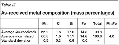
A typical tap consisted of 22 t of alloy and 17.6 t of slag. The tapping temperatures, as measured at the tap-hole, varied between 1420°C and 1520°C (however, see the note later regarding the likely difference between the measured tapping temperatures and the actual temperature inside the furnace). Slag and metal were sampled at each tap. The slag sample was taken with a metal rod in the launder and the metal sample in the metal ladle with a 'lollipop-sample' dipstick. Slag and metal compositions were determined by powdered X-ray fluorescence (XRF) analysis. The carbon content of metal samples was determined by LECO.
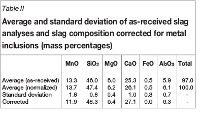
For the purpose of thermodynamic and kinetic calculations, the chemical compositions of slag and metal were normalized per tap for the six-component slag system (MnO, SiO2, MgO, CaO, FeO, and Al2O3, typical total 97.1%) and four-component metal system (Mn, C, Si, and Fe, typical total 99.8%). The average and standard deviation of the normalized results calculated for a 4-month period (November 2012 to February 2013) are reported in Table II and Table III. To correct the slag composition for entrained metal, it was assumed that all FeO in the slag was associated with entrained metal droplets with average composition shown in Table III. The assumption was validated through SEM-EDS analysis of a slag sample obtained from Transalloys - see Appendix A. Mass balance calculations were conducted to correct the slag composition for FeO, SiO2, and MnO, as reported in Table II.
Since the formation of SiC as a product of the reaction between slag or metal and carbon-based refractory material at tapping temperatures was demonstrated in laboratory-scale studies (Steenkamp et al., 2013; Molnás, 2012) and the reported tapping temperatures of 1420 to 1520°C were significantly lower than the tapping temperatures reported for SiMn elsewhere (Olsen, Tangstad, and Lindstad, 2007), it was expected that SiC tap-blocks would not show any significant chemical wear when placed in contact with SiMn metal or slag (however, see the note later regarding the likely difference between the measured tapping temperatures and the actual temperature inside the furnace).
Another aspect contributing to the expected reduced wear of the tap-hole was the use of reconstructive tap-hole clay (Table I). The purpose of reconstructive tap-hole clay is not only to plug the tap-hole at the end of the tap, but also to reconstruct the sidewall by forming a 'mushroom' of clay protecting the sidewall from slag and metal wear (Dash, 2009; Ko, Ho, and Kuo, 2008; Inada et al., 2009; Nelson and Hundermark, 2014). Evidence of a mushroom in the furnace was therefore expected at the time of the digout based on observations reported for ironmaking blast furnaces (Steenkamp et al., 2013; Molnás, 2011; Olsen, Tangstad, and Lindstad, 2007). However, Nelson and Hundermark (2014) (based on a paper by Tsuchiya et al. (1998)) suggested that a tap-hole clay mushroom is not typically formed in ferroalloy production furnaces if the coke bed does not extend to the tap-hole.
Oxygen lancing was frequently applied in opening the tap-hole or to keep it open, potentially contributing to increased wear of the tap-hole.
The condition of the tap-hole area was therefore of keen interest to the team involved in the investigation.
Method
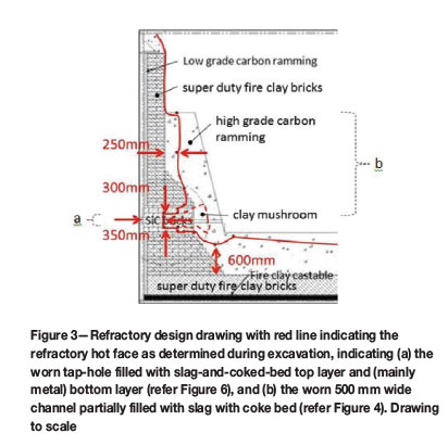
The top 2 m of the burden below sill level was dug out from the top of the furnace by manual labour. Thereafter the furnace was dug out from the side by excavating a circular sector of 120° between electrode 3 and electrode 1. The centreline of electrode 1 was positioned in the middle of the centrelines of tap-hole A and tap-hole B, which were positioned 60° apart. For the macro-scale investigation, photographs were taken of the refractory in situ, using a Canon EOS 30D camera installed on a tripod and triggered remotely. The camera settings for aperture and shutter speed were adjusted manually based on the lightmeter readings on the camera. Lighting was provided by free-standing floodlights, and no flash was used. The refractory thickness was measured with a tape measure and/or laser measurement device. The original design drawing was marked up with the measured wear profile (Figure 3).
Results
In Figure 3 the dimensions of the worn lining are superimposed onto the refractory design drawing presented in Figure 1. The dimensions of the red-line drawing were obtained on a vertical plane passing through the centre of the tap-hole.
As can be seen in Figure 3 and the series of photographs in Figure 4 to Figure 9, wear of the tap-hole area was extensive. As indicated in Figure 3, more than 50% of the SiC brick was worn away, with most of the wear occurring at the hot face of the sidewall. Wear of the SiC brick was more extensive above the tap-hole than below. Furthermore, the carbon ramming above the SiC brick was worn all the way to the top of the carbon. In plan view (not indicated), the wear pattern was in the form of a channel 500 mm wide, with fairly straight sidewalls rather than funnel-shaped as is typical of the wear pattern in open bath furnaces. The SiC brick and the carbon ramming paste in the hearth in front of the tap-hole were worn away both below and above the tap-hole.
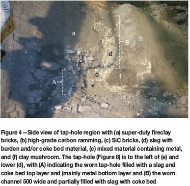
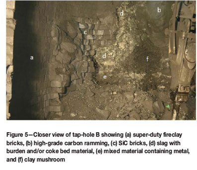
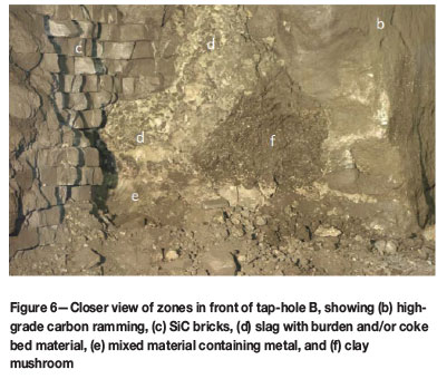
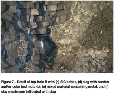
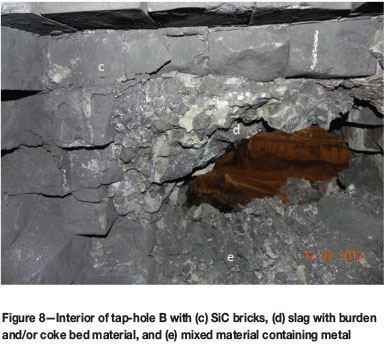
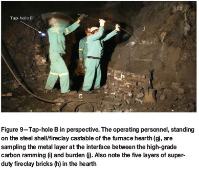
Figure 4 shows a side view of the tap-hole region (compare Figure 3) with the high-grade carbon ramming and SiC tap-hole extension (c) removed on the left-hand side, exposing the super-duty fireclay brick installed as back lining (a). On the right-hand side, the high-grade carbon ramming (b) was left intact. The 500 mm wide slot worn into the high-grade carbon ramming and SiC all the way vertically from the tap-hole to the top of the ramming crucible is clearly visible (d). The vertical slot was partially filled with a slag/burden layer (d) that extended into the upper part of the worn tap-hole. The lower part of the tap-hole was filled with mixed material containing metal (e). A clay mushroom, which formed when clay forced through the tap-hole spread radially when coming in contact with burden, was observed (f). Instead of the clay rebuilding the tap-hole by forming a new interface between the refractory and slag/metal, the slag and metal channelled around the clay mushroom before exiting the furnace through the worn tap-hole. Note that the mushroom was not in contact with the tap-hole, as would be expected of a reconstructive tap-hole clay (Dash, 2009; Ko, Ho, and Kuo, 2008; Inada et al., 2009; Nelson and Hundermark, 2014). The lack of attachment of the mushroom to the taphole broadly agrees with the suggestion by Nelson and Hundermark (2014) that ferroalloy furnaces generally do not develop a mushroom attached to the taphole.
Figure 5 and Figure 6 show the tap-hole area in close-up, making it easier to distinguish the different zones, comprising super-duty fireclay brick back lining (a), high-grade carbon ramming crucible (b), SiC bricks used to build the tap-hole (c), slag with burden and/or coke bed material present either in the worn channel (vertical section or upper (d)) or in the worn tap-hole (horizontal section or lower (d)), mixed material containing metal (e), and tap-hole clay mushroom (f).
Figure 7 and Figure 8 show the interior of the tap-hole, illustrating the extent to which the SiC brick in the tap-hole had worn away.
Figure 9 shows the tap-hole in perspective, with operating personnel standing on the steel shell/fireclay castable of the furnace hearth. This photograph was taken at the same stage of furnace excavation as was the photograph in Figure 8.
Discussion
The three main observations made during the excavation were as follows.
1. Contrary to expectations based on laboratory test work, the SiC brick in the tap-hole itself wore extensively. From laboratory-scale experiments it was expected that the C-based refractory material would wear, but not the SiC-based refractory material, as it was found that SiC formed as a product of the reaction between SiMn slag and C-based refractory material at tapping temperatures (Steenkamp et al., 2013; M0lnas, 2011)
2. Above the tap-hole, not only did the SiC brick extension wear but so did the high-grade carbon ramming. Wear took place in a channel 500 mm wide and extended to the top of the carbon ramming. Again, wear of the SiC was not expected, but should the C-based refractory material have come into contact with slag at tapping temperatures, reaction between slag and carbon would have been possible (Steenkamp et al., 2013). The fact that the channel extended to the top of the C-based refractory material was unexpected. The channel may have been worn by gas formed during lancing or evolved from the clay as reported for Ni matte smelters (Thomson, 2014) and PGM smelters (Nelson and Hundermark, 2014).
3. A clay mushroom did form, but rather than being attached to the SiC brick reconstructing the tap-hole, it was detached from the SiC brick and metal and slag channelled around it.
Potential refractory wear mechanisms
The refractory wear mechanisms reported for SAFs producing manganese ferroalloys are corrosion, densification, spalling, and erosion. Corrosionis caused by slag or metal components dissolving refractory components that they are not saturated with, or chemical reactions between refractory and slag, metal, or gas consuming the refractory materials (Hancock, 2006). Examples are alkali attack of carbon tamping paste (Brun, 1982), slag attack of carbon paste and tar dolomite brick (Brun, 1982), oxidation by water leakages (Tomala and Basista, 2007), and metal attack of carbon refractory (Tomala and Basista, 2007). Densification is caused by slag or metal penetrating pores and/or reacting with refractory (Hancock, 2006). Examples are alkali attack of alumina brick with subsequent volume increase (Brun, 1982) and metal penetrating open pores (Tomala and Basista, 2007). Spalling is caused by thermal stress across a single refractory body (Hancock, 2006), for example when hot face refractory material fractures and breaks away due to densification and/or thermal stress (Coetzee, Duncanson, and Sylven, 2010). Erosion is caused by slag, metal, and solid material abrading the refractory (Hancock, 2006). Of these mechanisms, corrosion, erosion, and spalling (which would be affected by densification) are all potentially applicable to the tap-hole area.
Potential for chemical reaction between slag or metal and refractory
In order to investigate the potential for chemical reaction (corrosion) between slag or metal and refractory as a mechanism contributing to the wear observed in the tap-hole area, thermodynamic calculations were conducted in FACTSage 6.4 (Bale et al., 2002). The Equilib model was used, and depending on the type of calculation the FToxid and/or FSstel and FACTPS databases were selected. Default gas, liquids, and solids were selected as pure species with duplicates suppressed, with the order of preference being the FToxid, FSstel, and then the FACTPS databases. As solution species, only liquid slag (SLAGA) and liquid metal (LIQU) were selected where applicable.
In all calculations the temperature range was 1500-1700°C at 25°C intervals and the pressure 1 atmosphere, although the ambient pressure at the plant is typically 0.85 atmosphere (Anon., 2014). The temperature range was selected based on the following criteria:
1. The process temperature required (by reaction thermodynamics) for the production of SiMn with 17.0% Si in equilibrium with slag with an activity of 0.2 (typical of SiMn production) is calculated as 1600°C (Olsen, Tangstad, and Lindstad, 2007)
2. The actual temperature experienced by the hot face refractories would therefore have been 1600°C or more.
Actual tap temperatures measured at the plant ranged between 1420°C and 1520°C. A difference between tapping temperature and process temperature of 50-100°C, caused by heat losses during tapping, is typical of plant operations (Olsen, Tangstad, and Lindstad, 2007). Flow modelling predicted that significant cooling of metal occurs as the metal flows to the furnace bottom and the taphole (Steenkamp et al., 2014).
To obtain an initial understanding of the system under investigation, the equilibrium phase distributions of both slag and the metal were calculated for the as-received and the corrected slag compositions in Table II and normalized metal composition in Table III. Initial conditions were not specified. For the slag calculations, 10 μg of argon was added to enable the calculation to converge.
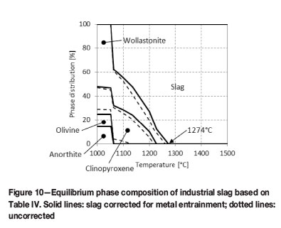
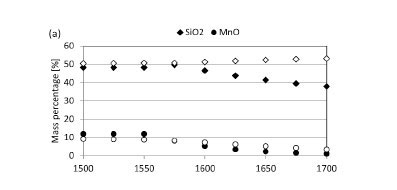
The predicted equilibrium phase compositions, for both as-received slag not corrected for metal entrainment and slag corrected for metal entrainment, are presented in Figure 10. In both instances the slag would be fully liquid at the temperatures under investigation (1500-1700°C) with the calculated melting points at 1260°C and 1274°C respectively. As the composition of liquid slag phase was not changed by the presence of a second phase, the slag composition in Table II could therefore be used 'as is' in thermodynamic calculations to study the potential of chemical reactions between slag and refractory.
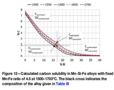
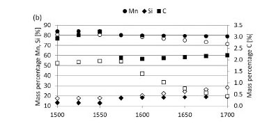
The predicted equilibrium phase composition of the as-received metal and chemical composition of the metal phase as a function of temperature are presented in Figure 11. At temperatures below 1625°C the metal is saturated in SiC, as seen by the precipitation of SiC as a separate phase and the lower Si and C contents of the liquid metal phase. As the temperature increases, the solubility of the SiC in the metal increases to the point (above 1625°C) where the metal becomes unsaturated in SiC. This is in agreement with the C solubility diagram for Si-Mn-Fe alloys presented in Figure 12 and constructed from thermodynamic calculations conducted in FACTSage 6.4 (Bale et al., 2002). Once the temperature has increased to such an extent that the metal is unsaturated in SiC, the metal will dissolve any SiC it comes into contact with, except for limitations posed by reaction kinetics (Einan, 2012).
The possibility of reaction was assessed by calculating the equilibrium phase distribution of the reaction products for the reaction of equal masses of slag and refractory as a function of temperature. Equal masses of slag and refractory were assumed for convenience; in reality, the refractories are exposed to large volumes of process materials (slag, metal) that are continuously being replenished by fluid flow past the hot face and due to new process material being continuously produced. This means that the effective ratio of process material to refractory material is usually very large, which may affect refractory consumption. Estimates of the actual quantity of slag participating in the reactions (based on mass transfer) are presented later. As the slag was fully liquid in the temperature range under investigation, the composition in Table II could be utilized in calculations. For the metal, the normalized composition in Table III was utilized. The fact that the metal was already saturated in SiC (and unsaturated in C) was taken into account when interpreting the results of the thermodynamic calculations. The refractory was assumed to consist of 100% C or 100% SiC.
The predicted equilibrium phase compositions when slag reacts with SiC or C refractories are presented in Figure 13, and chemical compositions of the slag, metal, and gas phases in Figure 14. The difference in phase composition of slag not corrected for metal and slag corrected for metal was insignificant. The remainder of the discussion will focus on slag corrected for metal only. This means that the elements actively participating in slag/refractory interaction were considered as being Mn, Si, O, and C (Fe excluded).
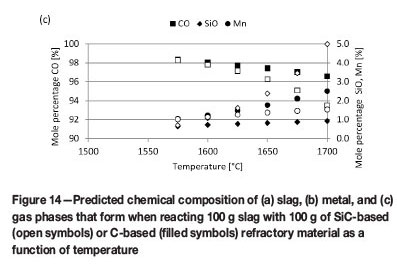
The reaction products for SiC-based refractory reacting with slag consist of metal and gas phases (Figure 13a). Metal formation is significant throughout the temperature range under investigation (1500°C to 1700°C). Metal formation increases with increasing temperature from 1575°C, which is the temperature at which gas formation also becomes significant. The formation of SiMn metal (Figure 14b) is associated with a decrease in the MnO content of the slag (Figure 14a), a decrease in SiC (Figure 13a), and formation of a CO-rich gas phase (Figure 14c). Wear of the SiC-based refractory was therefore due to the formation of a metal phase - through both the reduction of MnO and the subsequent dissolution of SiC into the metal phase formed -and formation of a CO-rich gas phase.
The reaction products for C-based refractory reacting with slag are metal, gas, and SiC phases (Figure 13b). Metal formation commences at 1525°C and SiC formation at 1575°C, with gas formation being significant from 1550°C. The formation of SiMn (Figure 14b), metal, and SiC is associated with decreases in both MnO and SiO2 contents of the slag (Figure 14a), a decrease in C (Figure 13b), and formation of a CO-rich gas phase (Figure 14c). Wear of the C-based refractory was therefore due to the formation of metal phase (through the reduction of MnO and SiO2 and subsequent dissolution of C into the metal phase formed), formation of a SiC-phase through reduction of SiO2, and formation of a CO-rich gas phase.
Refractory consumption
The predicted refractory consumption is plotted as kilograms of refractory consumed (Wref) per ton of slag or metal in Figure 15.
The highest wear predicted was for carbon-based refractory reacting with slag at temperatures exceeding 1675°C, followed by SiC-based refractory reacting with slag.
This is expected, as slag reactions involve both chemical reaction and dissolution as discussed above, whereas metal reaction involves only dissolution. Dissolution of SiC into metal (Figure 15b) occurs only once the metal becomes unsaturated in SiC (Figure 11a and Figure 12), whereas the metal is already unsaturated in C (Figure 12), with carbon potentially dissolving in metal throughout the temperature range (Figure 15a).
When C-based refractory reacts with slag, if the SiC reaction product were to form an in situ refractory layer at the slag/refractory interface, the potential for refractory wear by chemical reaction would be reduced (Lee and Moore, 1998). However, experimental work has shown that SiC detaches from the refractory rather than forming an in situ protective layer (Steenkamp et al., 2013; M0lnas, 2011).
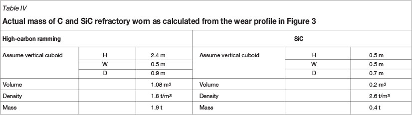
To put the results in Figure 15 into perspective, the actual refractory consumption was calculated over the lifetime of tap-hole B. The results are reported in Table IV. The mass of refractory worn was calculated from the wear profile in Figure 3. The total amount of slag tapped through the tap-hole was calculated from production figures (see Table V).
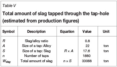
From Table IV and Table V the actual refractory consumption relative to the total amount of slag tapped through the tap-hole was calculated. The result obtained -0.07 kg refractory per ton of slag - was far lower (by a factor of a thousand) than the predicted equilibrium consumption (around 70 kg refractory per ton of slag, depending on temperature) (see Figure 15).
A likely explanation for the significant difference is that not all slag that was tapped through the tap-hole participated in chemical wear. According to the principles of fluid dynamics, velocity and diffusion boundary layers develop near the wall inside a circular pipe (tap-hole) due to the effects of viscosity. The boundary layers influence the heat and mass transfer in the pipe. In the case of slag/refractory interaction in the tap-hole, although equilibrium calculations indicate that SiO2 and MnO would tend to react with the refractory, only the SiO2 and MnO that diffuse through the boundary layer would be available to react with the refractory at the slag/refractory interface.
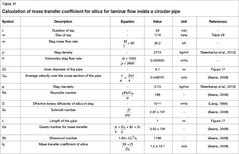
The amount of slag participating in the reaction was estimated from the mass transfer coefficient for laminar flow inside a circular pipe, taking account of entrance effects (Asano, 2006) (see Table VI). The transition from laminar to turbulent flow takes place at a Reynolds number (Re) of around 2300, therefore the flow in the tap-hole was taken to be laminar for slag tapping (see Re in Table VI). In this calculation, it was assumed that no freeze layer of slag would form on the refractory. This appears to be justified, based on the low slag melting point and the absence of forced cooling of the tap-block.
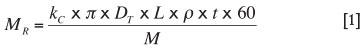
The rate at which slag is transported across the boundary layer to react with the interior surface of the tap-hole is given by the product of the mass transfer coefficient (k), the inner
area of the tap-hole, and the slag density; the proportion of slag reacting is then given by Equation [1]. This calculation indicates that the mass of slag reacting is approximately 0.01 kg per ton of slag tapped. Based on the estimate of 70 kg of refractory consumed per ton of slag tapped, the predicted refractory wear due to chemical reaction is 0.0007 kg per ton of slag tapped, two orders of magnitude smaller than the observed wear. The conclusion is thus that mass transfer effects in the tap-hole significantly limit the extent of reaction. It should be noted that wear by metal was not considered in this calculation; the mass transfer coefficient for metal (with lower viscosity and higher diffusivity) would be much higher than for slag.
Conclusions
One of the reasons for the excavation and reline of the 48 MV SiMn furnace was the high shell temperatures (300-480°C) in the vicinity of the tap-hole. Prior to the excavation, SiC brick used as tap-hole refractory (which should not react with slag) and reconstructive tap-hole clay used to form a mushroom attached to the refractory were expected to protect the tap-hole from wear.
The furnace excavation revealed two areas of high refractory wear - the tap-hole area and the furnace hearth. It was found that the SiC brick in the tap-hole itself wore extensively. Above the tap-hole, not only did the SiC brick extension wear but also the high-grade carbon ramming, with wear taking place unexpectedly in a channel 500 mm wide and extending vertically upwards to the top of the carbon ramming. A clay mushroom did form, but rather than being attached to the SiC brick reconstructing the tap-hole it was detached from the SiC brick, with metal and slag channelling around it.
Thermodynamic calculations predicted wear of both C-and SiC-based refractory through chemical reaction with slag and dissolution in metal. The SiC-based refractory wore when metal and CO-rich gas phases formed through the reduction of MnO in the slag and by the subsequent dissolution of SiC to form a SiMn alloy saturated in C and SiC. The C-based refractory wore when metal, SiC, and CO-rich gas phases formed through the reduction of MnO and SiO2 in the slag and by the subsequent dissolution of SiC and C to form a SiMn alloy saturated in C and SiC. The metal tapped from the furnace was typically saturated in SiC but not in C, therefore C-based refractory would dissolve in the metal and the SiC-based refractory dissolve at temperatures where the metal becomes unsaturated in SiC. The potential for chemical wear was therefore highest for C-based refractory material.
Furthermore, mass transfer calculations indicated that not all the slag tapped from the furnace was available for participation in chemical reactions responsible for wear. Comparison with estimated wear rates indicates that slag mass transfer was too slow to account for the observed wear. Although chemical reaction between slag and refractory is a potential mechanism responsible for refractory wear in the tap-hole, it appears not to be the only wear mechanism.
Further work to investigate flow conditions in the tap-hole region, and their possible effects on wear, would be useful, as would investigations into the effect of lancing and tap-hole clay studies.
Acknowledgements
The Management of Transalloys (Pty) Ltd for including me on the team excavating the furnace.
Johan Gous (Transalloys) for discussions and information on operational aspects of the furnace.
Johan Zietsman (University of Pretoria) for discussions on FACTSage modelling software and constructive questioning of my interpretation of the results.
The Management of the Centre for Pyrometallurgy, University of Pretoria, for utilization of the FACTSage software.
The PhD research project sponsor (who has chosen to remain anonymous) for providing guidance on the research topic in general and much-needed industry funding of the PhD project, of which the work presented here was part of.
The National Research Foundation of South Africa (Grant TP2011070800005) for leveraging the funding provided by the project sponsor.
References
Anonymous. 2014. Real time wind and weather report eMalahleni (9 January 2014 to 15 January 2014). www.windfinder.com [Accessed 16 January 2014]. [ Links ]
Asano, K. 2006. Heat and mass transfer in a laminar flow inside a circular pipe. Mass Transfer: From Fundamentals to Modern Industrial Applications. Wiley-VCH, Weinheim. pp. 89-100. [ Links ]
Bale, C., Chartrand, P., Degterov, S., and Eriksson, G. 2002. FactSage thermo-chemical software and databases. Calphad, vol. 26. pp. 189-228. [ Links ]
Brun, H. 1982. Development of refractory linings for electric reduction furnaces producing Mn alloys at Elkem A/S-PEA Plant, Porsgrunn, Norway. Journal of the Institute of Refractories Engineers, Spring. pp. 12-23. [ Links ]
Coetzee, C., Duncanson, P.L., and Sylven, P. 2010. Campaign extensions for ferroalloy furnaces with improved tap hole repair system. Infacon XII: Sustainable Future, Helsinki, Finland, 6-9 June 2010. pp. 857-866. [ Links ]
Dash, S.R. 2009. Development of improved tap hole clay for blast furnace tap hole. National Institute of Technology, Rourkela, India [ Links ]
Einan, J. 2012. Formation of silicon carbide and graphite in the silicoman- ganese process. Norwegian University of Science and Technology, Trondheim, Norway. [ Links ]
Hancock, J.D. 2006. Practical Refractories. Cannon & Hancock, Vereeniging, South Africa. [ Links ]
Inada, T., Kasai, A., Nakano, K., Komatsu, S., and Ogawa, A. 2009. Dissection investigation of blast furnace hearth-Kokura No. 2 blast furnace (2nd campaign). ISIJ International, vol. 49, no. 4. pp. 470-478. [ Links ]
Ko, Y., Ho, C., and Kuo, H. 2008. The thermal behavior analysis in tap-hole area. China Steel Technical Report no. 21. pp. 13-20, [ Links ]
Lee, W.E. and Moore, R.E. 1998. Evolution of in situ refractories in the 20th century. Journal of the American Ceramic Society, vol. 81, no. 6. pp. 1385-1410. [ Links ]
Matyas, A.G., Francki, R.C., Donaldson, K.M., and Wasmund, B. 1993. Application of new technology in the design of high-power electric smelting furnaces. CIM Bulletin, vol. 86, no. 972. pp. 92-99. [ Links ]
M0lnâs, H. 2011. Compatibility study of carbon-based refractory materials utilized in silicomanganese production furnaces. Norwegian University of Science and Technology. [ Links ]
Nelson, L.R. and Hundermark, R. 2014. 'The tap-hole' - key to furnace performance. Furnace Tapping Conference 2014, Muldersdrift, Gauteng, South Africa, 27-28 May 2014. pp. 1-32. [ Links ]
Olsen, S.E. and Tangstad, M. 2004. Silicomanganese production - process understanding. INFACON X: Transformation through Technology, Cape Town, South Africa, 1-4 February 2004. pp. 231-238. [ Links ]
Olsen, S.E., Tangstad, M., and Lindstad, T. 2007. Production of Manganese Ferroalloys. Tapir Academic Press, Trondheim, Norway. [ Links ].
Steenkamp, J.D. and Basson, J. 2013. The manganese ferroalloys industry in southern Africa. Journal of the Southern African Institute of Mining and Metallurgy, vol. 113. pp. 667-676. [ Links ]
Steenkamp, J.D., Gous, J.P., Pistorius, P.C., Tangstad, M., and Zietsman, J.H. 2014. Wear analysis of a taphole from a SiMn production furnace. Furnace Tapping Conference 2014, Muldersdrift, Gauteng, South Africa, 27-28 May 2014. Southern African Institute of Mining and Metallurgy, Johannesburg. pp. 51-64. [ Links ]
Steenkamp, J.D., Tangstad, M., Pistorius, P.C., M0lnâs, H., andMuLLER, J. 2013. Corrosion of taphole carbon refractory by CaO-MnO-SiO2-Al2O3-MgO slag from a SiMn production furnace. INFACON XIII, Almaty, Kazakhstan, 9-12 June 2013. pp. 669-676. [ Links ]
Thomson, L. 2014. Monitoring, repair and safety practices for electric furnace matte tapping. Furnace Tapping Conference 2014, Muldersdrift, Gauteng, South Africa, 27-28 May 2014. The Southern African Institute of Mining and Metallurgy, pp. 87-96. [ Links ]
Tomala, J. and Basista, S. 2007. Micropore carbon furnace lining. Infacon XI: Innovation in Ferroalloy Industry, New Delhi, India, 18-21 February 2007. pp. 722-727. [ Links ]
Tsuchiya, N., Fukutake, T., Yamauchi, Y., and Matsumoto, T. 1998. In-furnace conditions as prerequisites for proper use and design of mud to control blast furnace taphole length. ISIJ International, vol. 38, no. 2. pp. 116-125. [ Links ]
Paper received Jul. 2014
Revised paper received Sep. 2014.
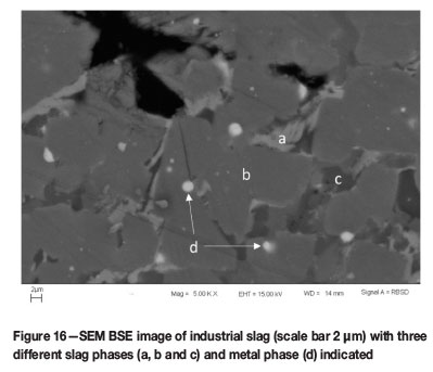
Appendix A. SEM-EDS analysis of industrial slag sample
To verify the assumption that no FeO was present in the slag, an industrial slag sample (supplied by Transalloys) was crushed and milled. A polished section was prepared and sputter-coated with gold.
The number of phases present in the slag samples was determined by FEGSEM (ZEISS LEO 1525 FEGSEM based at NMISA on the CSIR campus in Pretoria). The compositions of the phases were determined by EDS (Oxford INCA Energy System) at 15 kV (point analyses). Five different point analyses were conducted per phase.
Four different phases were identified - see Figure 16. Three were slag phases (a-c) and one metal phase (d). None of the three slag phases contained Fe. The only phase that contained Fe was the metal phase (d).

