


Services on Demand
Article
 English (pdf)
 Article in xml format
 Article references
Indicators

Related links
-
 Cited by Google
 -
 Similars in Google
Share

 Permalink
Journal of the Southern African Institute of Mining and Metallurgy
On-line version ISSN 2411-9717
Print version ISSN 2225-6253
J. S. Afr. Inst. Min. Metall. vol.114 n.12 Johannesburg Dec. 2014
A SOUTHERN AFRICAN SILVER ANNIVERSARY MEETING, 2014 SOMP
The presence of shear stresses in pillars and the effect on factor of safety in a room-and-pillar layout
J. A. Maritz
Department of Mining Engineering, University of Pretoria, Pretoria, South Africa
SYNOPSIS
Since the dawn of mining, pillars have been used as primary support to ensure stable workings. Early designs were based on trial and error, after which more scientific means developed over time. A vast amount of progress has been made, especially in soft-rock room-and-pillar design methodologies, from which hard-rock design theories developed with minor changes to constant parameter values. The commonly used Hedley and Grant method for hard rock and Salamon and Munro methodology for soft rock draw on the tributary area associated with the pillar, the width-to-height ratio of the pillar, and a back-analysed strength reduction factor. In these methods, only the vertical stress, or stress normal to the pillar influences the load applied to the pillar. This investigation considers the possible influence of shear stresses on pillars in a room-and-pillar layout in single reef planes and multi-reef environments, based on elastic numerical modelling methods. The possible shear stress poses a safety and financial risk to the design process, whereby an undersized pillar would lead to unstable working conditions, whereas oversized pillars could lead to an under-utilized ore resource.
Keywords: numerical modelling, shear stress, factor of safety.
Introduction
In recent times, mining of multi-reef horizons in hard-rock mines has attracted more attention. As these multi-reef environments are not yet fully understood and complex pillar stress regimes exists in these cases, design methodologies are adopted from other methods that have been successful in the past (e. g. Hedley and Grant application in single-reef hard-rock situations, adapted from Salamon and Munro for coal pillar designs).
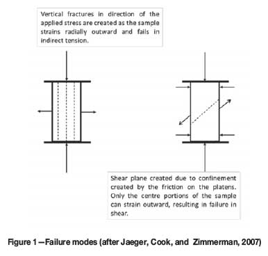
It is known that a rock sample under uniaxial loading conditions will fail in one of the possible two modes; either indirect tension, when the ends have a low friction angle, or shear, when the ends (or the complete sample) are confined (Jaeger, Cook, and Zimmerman, 2007). A schematic of these two modes of failure is shown in Figure 1.
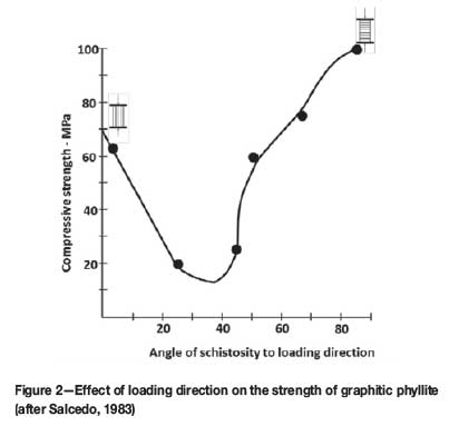
Furthermore, the uniaxial compressive strength differs greatly as the loading direction relative to the schistosity is changed (Salcedo, 1983). Hence, if the loading of the pillar is not perpendicular, as is assumed by the tributary area theory, and the direction of loading is not normal to the horizontal state of schistosity in the pillar, the pillar strength will be less than initially anticipated (Figure 2).
The purpose of this paper is to determine if the mining environment - including the dip of the mining horizon, the depth of extraction, and instances where multi-reefing is practiced - materially affects the loading of pillars, and the resulting influence of a possible shear stress component on the assumed factor of safety.
All modelling in this paper was done using the TEXAN numerical modelling code (Napier and Malan, 2007).
Complex pillar-loading environment
Room-and-pillar layouts for hard-rock mines are commonly designed based on the methodology of creating an environment in which the ratio between the pillar strength and pillar load, commonly known as the factor of safety (FoS), is satisfactory (Equation [1]).
1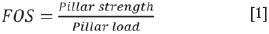
'Stable' coal designs are considered to have safety factors of 1.6 and above. Jager and Ryder (1999) commented that the same should apply to hard rock.
Following the successes of the Salamon and Munro (1967) pillar strength formulation, the same approach was sought in the hard-rock environment. The Hedley and Grant (1972) strength methodology followed a few years later, fitting limited information from field studies. Equation [2] shows the formula used in determining the strength of a square pillar.

where K represents the pillar strength constant (downgraded uniaxial compressive value), w the width of the pillar, and h the height at which the mining is taking place. In the South African hard-rock mining industry, the values of K can range from 35 MPa for initial design calculations to around 60 MPa after back-analysis on actual pillar performance. The ranges are based on one-third of the UCS values of the typical rock mass in the hard-rock industry, which range from 100 to 180 MPa.
The lower limit for K is generally assumed as a first estimate when designing a room-and-pillar mine. After some mining has been done, leaving pillars based on the initial design parameters, and an increased confidence in the input parameters has been gained, the K value of that specific mining application could be back-analysed by means of elastic modelling to obtain a K value reflecting the conditions observed.
The loading of the pillar could also be calculated based on the tributary area theory (TAT), which assumes that the weight of the overburden directly above the pillar plus that halfway to the next pillar is being carried by the pillar. In application, the conservative TAT ignores the fact that the presence of abutments in a mining area results in a different distribution of stresses, and assumes that the mining area has a regular geometry extending over an infinite area.
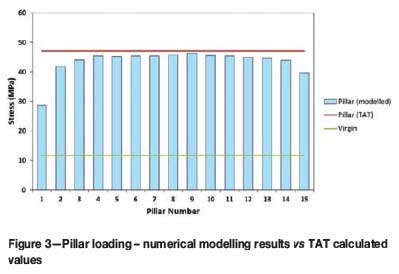
The TAT assumptions can be shown to be valid by simple numerical modelling, e.g. by simulating a 240 m x 240 m room-and-pillar area with parameters as presented in Table I.
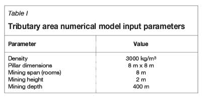
For the mining environment defined in Table I, the calculated vertical virgin stress level would be 11.8 MPa.
Figure 3 illustrates the values of the modelled pillars compared to the calculated TAT load on each pillar. The pillars towards the edges of the model indicate lower levels of stress since they are influenced by 'abutments', as seen by the numerical modelling package. It also highlights the increase in pillar load from virgin stress levels prior to mining. Figure 3 indicates that where the assumptions of the TAT are met (towards the middle of the modelling area), the modelled pillar stress level approach the calculated APS (Average Pillar Stress) values. Hence, if normal loading is the only stress applied to the pillar, TAT can be assumed to be a valid methodology to follow.
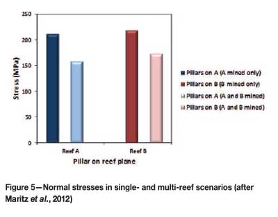
If the mining environment changes and the conditions of loading change, so should the considerations and application of the standard formulae. As proven by Maritz et. al. (2012), in multi-reef scenarios, normal stress levels reduce while shear stresses increase on the pillars for horizontal environments.
Maritz et al. simulated a multi-reef, 16 m x 144 m stabilizing pillar (0° dip) where the pillar stresses on the two reef horizons (Reef A and Reef B) were compared, firstly with only Reef A being mined, and then comparing the pillar stresses when the second reef had been extracted. The middling between the reefs was set at 35 m (Figure 4), with the pillars on Reef A and Reef B being superimposed.
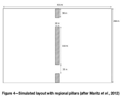
Figure 5 depicts the reduction in normal stresses on identical superimposed room-and-pillar layouts from a single-reef environment to a multi-reef scenario, whereas Figure 6 highlights the shear stresses on the Reef B pillar in the multi-reef scenario.
The significance of Figure 6 is that when Reef B is analysed in isolation (Reef A ignored), no shear stresses are present on the pillar. Shear stresses appear as soon as Reef A is considered.
As the complex interaction of stresses in a multi-reef scenario is now apparent, this paper will investigate the changing ratios between normal and shear stresses on pillars as the reef dip angles changes and when multi-reef scenarios are introduced.
Simulating the effect of dip and mining depth
The effect of dip and mining depth on shear stress levels on a pillar will be investigated using the excess shear stress (ESS) - Equation [3]:

The simulated shear stress ( max) on a plane is resisted by a function of the friction angle (μ=tan
 ) and the normal 'clamping' stress (σn).
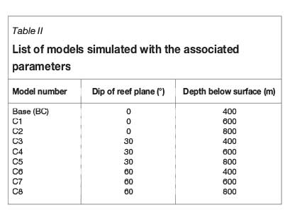
Positive ESS values suggest an unstable condition in the sense that shear failure could occur since the driving stress ( max) exceed that of the shear strength (μσn). A number of TEXAN simulations (Table II) were conducted on a standard 240 m x 240 m room-and-pillar layout (Figure 7) to ascertain the effect of dip and mining depth on the shear stress levels.

On a horizontal plane, as the depth increases the 'clamping' stress increases, hence reducing the ESS levels and resulting in a more stable shear environment. The plane assumed for the purpose of the ESS calculations was the contact between the pillar and the hangingwall. Figure 4 depicts the increasing level of stability on a horizontal plane at varying depths. ESS is simply a function of normal stress (increasing with depth) times the coefficient of friction, since the modelled shear stress component is zero. These ESS values are presented graphically in Figure 8.
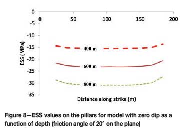
The expected change in ESS becomes more obvious in the cases where the dips change. When the dip increases, the driving shear stress increases, the normal stress reduces, and therefore indicates likely instability with ESS values approaching zero. Figure 9 depicts the change in the ESS values as the dip of the modelled horizon is increased.
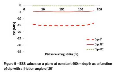
The chances of observing ESS levels such as these in the South African context are considered to be very unlikely, since the hard-rock mining industry does not commonly employ room-and-pillar layouts on reefs with dip angles exceeding 15°.
Shear stress on stability pillars
Regional stability could be achieved by designing stability pillars, either on dip or along strike. These pillars are designed to control the energy release rate (ERR) associated with the mining span, reducing the incidence of seismic events and rockbursting at working stope faces (Jager et al., 1999).
The shear stress values have been again scrutinized by means of a TEXAN set of numerical models comparing the dip configuration with the strike layout. A schematic of the two layouts is presented in Figure 10.
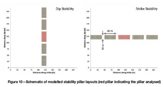
The model was set up with the parameters presented in Table III.
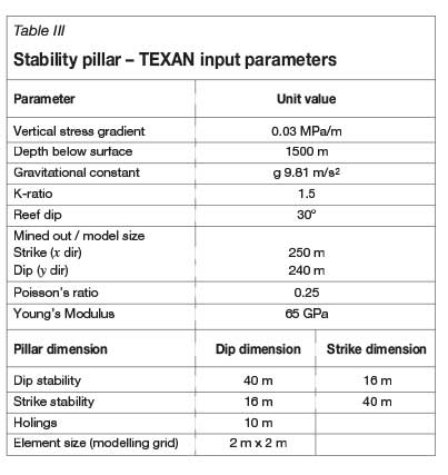
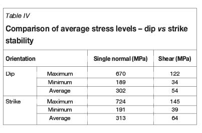
The resulting values are summarized below. From the analysis it was found that the APS on the strike orientation exceed that of the dip layout by 4% and the shear stress by 19%. The values obtained from the numerical modelling analysis are presented in Table IV.
The shear stresses in the dip direction are presented in Figure 11.
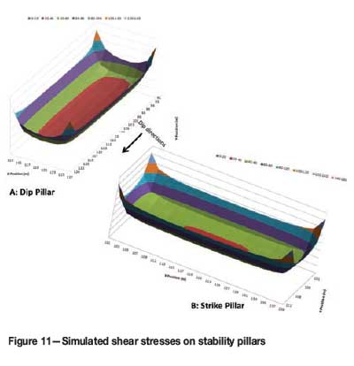
High shear stress peaks are observed on the pillar edges, reducing in magnitude as the core is approached. In Figure 11A the area of the red contour (lower stress levels) far exceeds that of strike pillar presented in Figure 11B. Being an elastic numerical model, the results indicate the reason for dip pillars being a better regional support, taking into account the K-ratio applicable to the environment and the ride direction.
The plot of the shear and normal stress in the ESS context (Figure 12) leads to similar conclusions with respect to the better layout in a dipping environment.
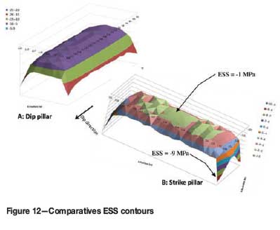
The ESS contours on the strike-orientated pillar indicate large areas where the ESS levels are approximately zero, indicating possible areas of instability (a positive ESS denotes instability). The dip pillar reflects a better tendency towards stability.
Factor of safety
As mentioned previously, the ratio between the pillar strength and pillar load should be designed to a value of 1.6. This entails that an optimal extraction should be pursued that shows economic value as well as providing the rock mass stability needed to ensure a safe working environment.
As discussed earlier in this paper, the loading could be calculated either by the TAT approach, considering the limitations and applications of the theory, or by means of numerical modelling. For the purpose of calculating the FoS in this section, the loading will be taken as that calculated during the numerical modelling process.
The foregoing analysis considers only the axial loading (normal stress), whereas Swart et al. (2000) suggested the strength-to-load ratio representing the FoS should be revised to include the shear stress levels of the pillar load stress matrix. A graphical representation is given in Figure 13.
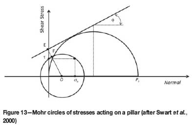
In Figure 13, σn depicts the normal stress on the pillar. and PS represents the uniaxial pillar strength. Swart et al. suggest that where the standard FoS equation is calculated by Ps/σn the real safety factor should be presented by OE/OF.
The suggested FoS equation for inclusion of the shear component is:
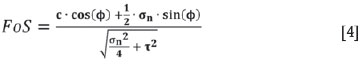
with c being the cohesion and  the friction angle. The stresses are given by σn for the normal and
  for the shear component.
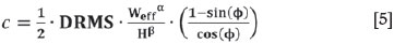
Swart et al. also expressed the cohesion in terms of the downgraded strength of the rock mass (DRMS):
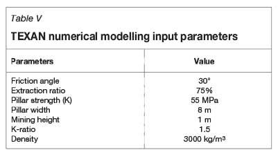
A TEXAN model had been set up to illustrate the variance in FoS values when including and excluding various parameters. The model was adjusted to simulate a room-and-pillar layout at various dip angles (0° to 40°) so as to 'generate' a shear stress component on the pillars. The input parameters to the model can be read in Table V.
For illustrative purposes, the two versions of the FoS are calculated for each scenario - firstly, using the Hedley and Grant methodology for hard-rock strength calculation; and secondly, the Swart methodology, including the shear stress. Table VI summarizes the findings of this comparison.
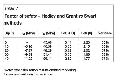
Table VI shows that the FoS is reduced by around 37 per cent on average when the Swart formula is applied, suggesting a reduction in the extraction ratio to accommodate a safe environment. The Swart formula even suggests a reduction in the safety factor with no shear stress present, given the same strength constant in both formulae.
Conclusions
The complex loading environment in a room-and-pillar layout was investigated for both dipping and multiple reef scenarios. The existence of shear stress components as part of the pillar loading in a room-and-pillar layout has been identified by means of TEXAN numerical modelling code. From the elastic numerical modelling results, it can be concluded that the stress and loading regime of pillars is highly influenced by various factors, including the dip of the reef horizon, depth below surface, and multi-reef scenarios.
The orientation of larger scale pillar, such as regional stability pillars, seems to have some significance when the shear component is analysed. It appears that both the normal and the shear component for dip stability pillars are less than for the strike counterpart.
If consensus is achieved on which of the pillar strength formulae applies to the pillars in the extraction area, the influence of the shear stress, which reduces the safety factors, should be taken into account. It can thus be concluded that the tributary area theory and formula, which is believed to be conservative initially, might not be so conservative after all in cases where shear stresses are present.
Acknowledgements
This work forms part of the author's MEng studies at the University of Pretoria.
References
Bieniawski, Z.T. 1992. A method revised: coal pillar strength formula based on field investigations. Workshop on Coal Pillar Mechanics and Design. IC 9315. US Bureau of Mines, Pittsburgh, PA. pp. 158-165. [ Links ]
Hedley, D.G.F. and Grant, F. 1972. Stope-and-pillar design for Elliot Lake Uranium Mines. CIM Bulletin, vol. 65. pp 37-44. [ Links ]
Jaeger, J.C., Cook, N.G.W., and Zimmerman, R.W. 2007. Fundamentals of Rock Mechanics. Wiley-Blackwell. [ Links ]
Jager, A.J. and Ryder, J.A. (1999). A Handbook on Rock Engineering Practice for Tabular Hard Rock Mines. Safety in Mines Research Advisory Committee, Johannesburg. [ Links ]
Madden, B., Canbulat, I., and York, G. 1998. Current South African coal pillar research. Journal of the South African Institute of Mining and Metallurgy, vol. 98, no. 1. pp. 7-10. [ Links ]
Maritz, J.A. and Malan, D.F. 2011. The influence of shear stress and weak contacts on pillar behaviour. 12th ISRM International Congress on Rock Mechanics, Beijing, 18-21 October 2011. [ Links ]
Maritz, J.A., Malan, D.F., and Piper, P.S. 2012. Estimating pillar stresses in complex multi-reef layouts. Southern Hemisphere International Rock Engineering Symposium, Sun City, South Africa, 14-17 May 2012. pp. 125-143. [ Links ]
Napier, J.A.L. and Malan, D.F. 2007. The computational analysis of shallow depth tabular mining problems. Journal of the Southern African Institute of Mining and Metallurgy, vol. 107, no. 11. pp 725-742. [ Links ]
Salamon, M.D.G. and Munro, A.H. 1967. A study of the strength of coal pillars. Journal of the South African Institute of Mining and Metallurgy, September 1967. pp. 56-67. [ Links ]
Salamon, M.D.G. and Wagner, H. 1985. Practical experiences in the design of coal pillars. Proceedings of the 21st International Conference of Safety in Mines Research Institutes, Sydney, 21-25 October 1985. CRC Press. [ Links ]
Salcedo, D. 1983. Macizos Rocosos: Caracterizacion, Resistencia al Corte y Mecanismos de Rotura. 25 Aniversario Conferencia Soc. Venezolana de Mecdnica del Suelo e Ingenieria de Fundaciones, Caracas. pp. 143-172. [ Links ]
Swart, A., Keyter, G., Wesseloo, J., Stacey, T., and Joughin, W. 2000. Influenace of surface topography on the loading of pillar workings in near surface and shallow mines. Safety in Mines Research Advisory Committee, Johannesburg. [ Links ]

