


Services on Demand
Article
 English (pdf)
 Article in xml format
 Article references
Indicators

Related links
-
 Cited by Google
 -
 Similars in Google
Share

 Permalink
Journal of the Southern African Institute of Mining and Metallurgy
On-line version ISSN 2411-9717
Print version ISSN 2225-6253
J. S. Afr. Inst. Min. Metall. vol.114 n.10 Johannesburg Oct. 2014
6TH SOUTHERN AFRICAN ROCK ENGINEERING SYMPOSIUM
Unique fall-of-ground prevention strategy implemented at Two Rivers Platinum Mine
A. Esterhuizen
Open House Management Solutions (Pty) Ltd
SYNOPSIS
Since 2005 Two Rivers Platinum Mine has set out on an initiative to actively monitor and control ground conditions on a daily basis, by making use of borehole cameras and pro-actively amending the support and mining strategies based on day-to-day observations of the hangingwall conditions. Today the borehole camera observations form part of the Rock Engineering Department's daily function, and the size and frequency of falls of ground and ensuing accident rates have been drastically reduced since implementation of the system. The Two Rivers Platinum fall-of-ground management system aims to support 100% of the possible fallout thickness, based on ongoing data gathering and interpretation, thereby ensuring safety and limiting support cost.
Keywords: strata control, fall-of-ground management.
Introduction
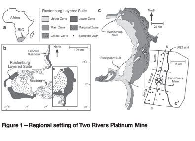
Two Rivers Platinum Mine, a joint venture between African Rainbow Minerals (ARM, 55% ownership and management) and Impala Platinum (45% ownership and smelting, refining, marketing), is situated on the eastern limb of the Bushveld Complex near the town of Steelpoort in Limpopo Province (Figure 1). The mine is underlain by rock formations of the Critical Zone (Winterveld Norite-Anorthosite) and the Main Zone (Winnaarshoek Norite-Anorthosite). Two economically significant PGM-bearing horizons, namely the UG2 chromitite and Merensky Reef, are located in the Upper Critical Zone, separated by approximately 140 m of norites and anorthosites. The UG2 chromitite seam is extracted through mechanized bord and pillar mining at a rate of 300 000 t per month at an average ore grade of 4.10 g/t (PGE + Au). The underground workings on the UG2 horizon are currently between 40 m and 800 m below surface, at an average orebody dip of 9 degrees, and are accessed through two decline shafts roughly 3 km apart. The Merensky Reef is extracted on a similar bord and pillar mining layout, currently approximately 30 m below surface. The Merensky Shaft is planned to extract 14 500 t of ore per month in the trial mining phase, and thereafter it will build up to 180 000 t/month.
Regional geology
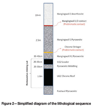
The UG2 chromitite layer has been intersected in over 100 boreholes on the host farm Dwarsrivier. The lithological sequence, from the base upwards is illustrated in Figure 2. The UG2 reef horizon lies within a competent pyroxenite band, which extends 2.5 m into the hangingwall and up to 1 m in the footwall. The Footwall 1 Unit is coarse-grained to pegmatoidal pyroxenite/harzburgite and is approximately 1 m thick.
The UG2 averages approximately 180 cm in thickness, and internal pyroxenite and norite partings may be present. These in some cases have highly angular margins and appear to have been derived from erosion and transport within the UG2 of pre-existing layers. To the south and deep central part of the farm, a large area is characterized by the presence of split reef, whereby a pyroxenite or norite lens up to 6 m thick is situated approximately two-thirds from the base of the UG2.
Disseminated sulphide mineralization is generally present, especially around the margins of internal pyroxenite partings. This mainly comprises pentlandite and chalcopyrite, with lesser pyrrhotite. There is minimal cohesion between certain layers due to the mineral composition of the contacts.
The UG2 is overlain by poikilitic pyroxenite that hosts up to three chromitite 'leader' layers (collectively termed the UG2A chromitite layers). The pyroxenite is intersected by three major joint sets; Joint set J1 dips at approximately 85° and has a strike of approximately 050° E of N; Joint set J2 dips at approximately 85° and strikes 120° E of N. Joint set J3 dips at 70° to 80° and strikes 080° to 100° E of N. The jointing extends through the reef into the footwall, but rarely extends into the HW2 anorthosite.
The UG2 reef horizon is divided into two portions, the UG2 proper (1.8 m), and the UG2 Leader reef (30-40 cm) by an internal pyroxenite layer (30-40 cm). The mining property is also affected by numerous features related to late-stage Bushveld intrusions. These include potholes and Fe- and Mg-enriched replacement pegmatoid bodies emplaced into the Bushveld cumulate stratigraphy. Generally, thinning of the reef layer, coupled with the steep and erratic dips around the potholes, results in a total ground loss during underground mining operations. Potholes are present on varying scales, from the large regional potholes that affect the Merensky stratigraphy in the northwestern Bushveld Complex to small circular features less than 10 m in diameter. Current information at Two Rivers suggests that potholes affect both the Merensky pyroxenite and the UG2. These potholes are envisaged to be similar in their development to those encountered in the western Bushveld Complex. However, no indications of regional potholes affecting the Merensky stratigraphy have been identified.
Numerous wide dolerite dykes intersect the mining property, striking in NW-SW and NW-SE directions. The dykes are brittle, but generally easily negotiated with few stability-related issues.
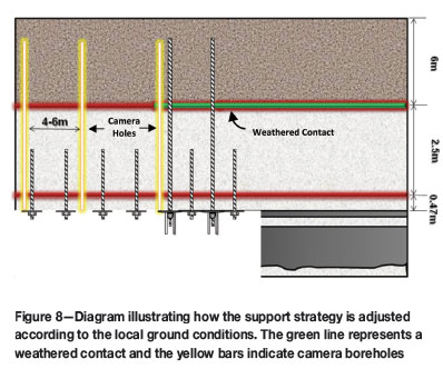
The pyroxenite is prone to weathering, especially in the shallower workings of the mine where some water inflow is experienced. The oxidation of specifically the contact between the HW1 pyroxenite and HW 2 anorthosite, referred to as the HW 1/2 contact, is problematic and resulted in numerous large collapses during the mine's early history. It is the weathered nature of this contact, which is located 2.5 m above top of UG2, and the necessity of observing its condition, that led to the implementation of the borehole camera system.
Mine layout
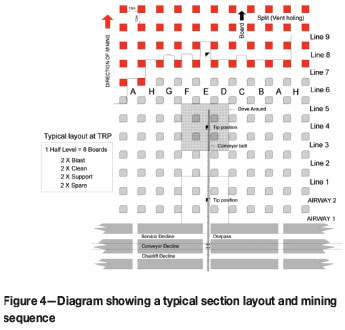
The mine is laid out in a regular checkerboard bord and pillar layout, with panel widths ranging between 6 m and 12 m, depending on the rock mass rating. Elastic pillars are designed according to the Hedley and Grant pillar formula and increase in size with increasing depth below surface. Shaft stability is ensured by means of squat pillars. Although the orebody dips at 9-11 degrees, the mine is undercutting a mountain, which results in a rapid increase in depth below surface.
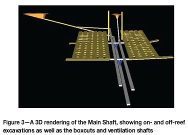
Two Rivers Platinum is a fully mechanized mine, which perfectly suits the orebody geometry, with nine half-levels (sections) on the Main Shaft and seven half-levels on the North Shaft. A section consists of at least eight panels and is mined with a fleet consisting of three load haul dumpers (LHDs), one roofbolter, one drill rig, one utility vehicle, and one emulsion utility vehicle (UV). Currently the mine is producing roughly 300 000 t of ore per month through the two shafts. Each section is equipped with a strike conveyor, which in turn tips on the main belt through an orepass.
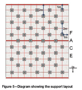
Support
As regional support, elastic pillars are left on a checkerboard pattern, designed with a factor of safety >1,6 and width to height ratio > 3. Due to the frequency and size distribution of the potholes and other major geological features such as shear zones and dykes that are left unmined, no regional/ barrier pillars are purposely designed.
As in-stope support, 1.5 m long x 18 mm diameter full column grouted resin bolts are installed spaced 1 m x 2 m apart to a diamond pattern. The support is installed using 60-second spin-and-hold resin and is aimed primarily at key block suspension and beam building. Where the need to suspend the entire HW1 beam is identified by means of borehole camera observation, 4 m long, 18 mm diameter (380 kN) pre-tensioned, full column grouted cable anchors are installed. The mine currently installs roughly 22 000 bolts and 3 000 cable anchors per month. An average of 3 000 m2 of shotcrete and thin sprayed liners is also applied per month in friable areas.
Major geological features such as shear zones and dykes are left unmined to prevent off-reef mining and exposure of employees to hazardous ground. Where excavations have to traverse wide shear zones, the sheared and weathered HW1 pyroxenite makes conventional drilling and installation of support impossible. In these conditions the HW1 pyroxenite is removed as the HW2 anorthosite behaves significantly better under these conditions.
Analyses of fall-of-ground data and implementation of a strata control system
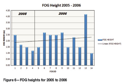
Shortly after the onset of mining in 2005, massive falls of ground (FOGs) occurred at a rate of 0.8 collapses per month. Some of these collapses were a result of wedge failure brought about by the interaction of the normal near-vertical joints with flatter low-angle or domed joints. The main cause of most of these collapses was found to be the inability of the inexperienced mining crews to identify and timeously support the structures. Of concern, though, was the high frequency of collapses extending up to the HW1/2 contact, which resulted in fallout thicknesses of up to 2.5 m, which is far above the effective length of the installed primary support. These collapses were unexpected, as the initial geotechnical studies and risk assessment did not identify this particular contact as being of high potential risk. By the end of 2006, 50% of all collapses dislodged from this contact.
Examination of the collapses identified early on that the HW1/2 contact and HW1 pyroxenite are prone to oxidation, which reduces the cohesion and self-supporting ability of the beam. The beam would then collapse between joints and could extend up to 20 m in strike length.
The following conclusions were made based on FOG analyses:
► As the contact is located mine-wide at a fairly consistent distance above the UG2, it was obvious that determination of the physical condition of the contact, and not only the location of the contact, was crucial
► Due to weathering in certain areas of the mine, beam building was not being achieved by the installed support, as alteration on joint walls, and subsequent reduction in cohesion, allowed blocks to rotate and slide out between support units
► Total suspension of the pyroxenite beam is required under certain conditions
► Production personnel were unable to successfully identify low-angle/domed-shape joints, which accounted for the other 50% of collapses
► There was an urgent need to identify areas where the HW1/2 contact was likely to be oxidized
► Low-angle joints are scattered randomly across the mining property, but joint mapping showed that these features tend to cluster around large potholes.
Based on the findings of the analyses, a FOG management plan was implemented, based on local experience and observations.
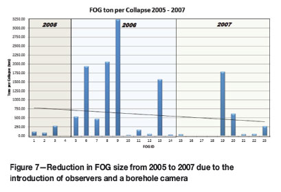
Based on the identified requirements, two strata control observers were employed to assist with daily underground data acquisition and identification of weathered ground conditions and low-angle features. In order to assist with the inspection of the HW1/2 contact, a borehole camera was purchased. The camera was used on an ad-hoc basis where the need was identified and did not form part of the normal daily routine.
In addition to the modifications to the Rock Engineering Department structure, the production team was given regular underground training in the identification and treatment of low-angle joints. The original risk assessment was updated and the current support at the time, resin bolts, was supplemented with additional 4 m cable anchors where deemed necessary. A great deal of attention was given to raising awareness amongst mining personnel with regard to low-angle features and the problematic HW1/2 contact.
The changes to the strata control system proved to be a step in the right direction. Although the >2 m high collapses were not entirely prevented, the overall size of the collapses was reduced due to the installation of cable anchors where deemed necessary.
In early 2008 the mine suffered another massive collapse. This time the collapse occurred in a previously identified and supported area, and trapped a LHD. Investigation showed that the extent of the unstable area was underestimated during the initial support recommendation and, in addition, the installed support spacing was not in accordance with the Rock Engineering recommendation.
Based on the prior success gained from the addition of observers and borehole cameras, it was decided to continue and improve on this system, which at the time was new and not used on a daily basis in South African mines.
The Rock Engineering Department staff complement was extended to include an observer and a borehole camera for each section. The borehole inspections now became part of the daily functions of the rock engineering observers, as well as daily inspections of all available working panels. This information was then relayed back to the strata control officer and mine overseer on a daily basis for recommendation and communication. All installed support was inspected and the support spacing measured on a daily basis, with weekly over-inspections of all cable anchors and applied thin-skin liners. The mine's support standard was amended to ensure that two dedicated camera holes were drilled with every support round. The holes are 4 m deep and 40 mm in diameter, spaced no more than 4 m apart, and drilled midway between the center line and the sidewalls. After drilling, the holes are clearly demarcated and no support units may be installed in these holes. In addition, the width of excavations mining in, or advancing through, deteriorated ground conditions was reduced from 12 m to 6 m, reducing exposure of weakness planes.
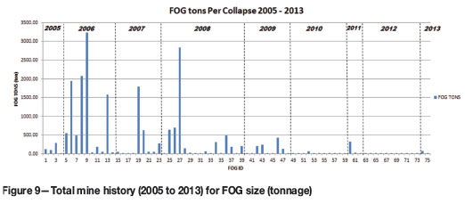
The success obtained through this system is self-evident when one considers the mine's total FOG history from 2005 to 2011. There has been a clear and significant improvement in the FOG height and overall size since the introduction of the camera system. The fallout size has been reduced to the point where, since 2010, most FOGs are barring-related incidents.
The system incorporated at Two Rivers Platinum Mine, along with detailed daily over-examination of working panels by competent persons and proper training of production personnel, resulted in a proactive system where potentially unstable ground is identified and assessed on a daily basis. The borehole camera system is quick, simple, and easy to understand. Feedback to mining personnel is immediate and visual, which helps foster trust and appreciation of the system amongst miners, which in turn helps to ensure compliance to the standard.
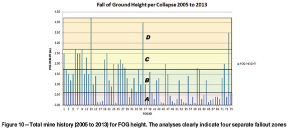
Using the information obtained from the borehole camera observations and FOG investigations, it became apparent that the mine has four different fallout height zones, and if these zones can be correctly and timeously identified, 100% of the fallout height can be supported 100% of the time, without resorting to a mine-wide blanket worst-case scenario support design. The zones include:
A. Stringer collapse (0.5 m height)
B. Low-angle joint wedge collapse (1.5 m height)
C. HW1/2 beam collapse (2.5 m height)
D. Shear zone self-mining (up to 4 m height).
Figure 10 indicates that the 2.5 m high collapses related to the hangingwall anorthosite/pyroxenite contact (zone C) have basically been eradicated. This is a result of the ability to identify and treat the structure where necessary. Also obvious is the continuance of the 1.5 m high collapses (zone B). These collapses are related to low-angled joints and domes, which are randomly spaced and oriented, and harder to identify and treat. Approximately 90% of all low-angled joint/dome collapses on Three Rivers Platinum occur in the unsupported area between the face and the last line of support immediately following or concurrent with the blast. The lack of these collapses in the supported area pays tribute to the ability of the entry examination team, in conjunction with the relevant service departments, to identify and treat the structures.
All designs and assumptions regarding fallout thickness are based on a detailed actual FOG database. Every incident is thoroughly inspected, regardless of the size or consequence of the collapse. Despite the thoroughness, only 75 cases were investigated over a period of eight years, representing less than 0.05% of the total mined area. In order to verify the conclusions, and to gain confidence in the assumptions, a synthetic database was created, using the software package JBlock. JBlock allows for the creation of a jointed beam based on given joint set parameters. The resultant key blocks can then be analysed for stability.
Actual vs. synthetic database
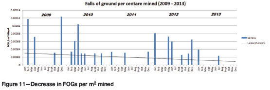
The mine's FOG database shows that the number of collapses per square metre mined has steadily decreased since the introduction of the current strata control system. Although this is a desirable result of an effective system, it limits observational ability, and with it, the opportunity to learn and gather information. As with any statistical information, a larger FOG database will provide more accurate output and provide more confidence in the assumptions made during the design process.
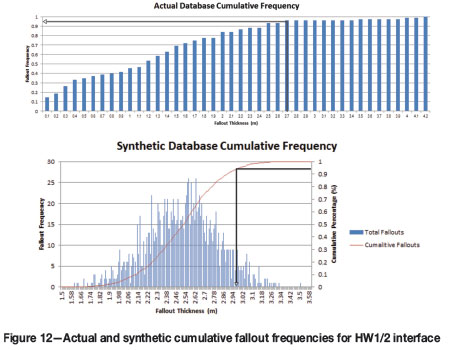
Jblock was used to create a synthetic database, in order to supplement the actual database and verify the conclusions. Using Jblock, 10 845 mining steps (advance blasts) and 1.17 million square metres were simulated, which resulted in the analyses of 20 000 key blocks with 5 iterations per block. The results obtained were very similar to the actual database, and confirmed the prediction of four fallout height zones.
The results of the synthetic database, shown in Figure 12, were obtained by inserting a hangingwall-parallel contact at the actual location of the anorthosite/pyroxenite interface. The results indicate that the 95% FOG height is 2.95 m, with a maximum expected apex height of 3.58 m. The actual database concluded that the 95% FOG height is 2.7 m, and that the highest actual collapse was 3.5 m. There were other higher collapses in the actual database, but these were related to self-mining shear zones, and did not dislodge from the hangingwall contact. As the contact location is consistent at 2.5 m above the reef, an associated collapse with a fallout height of 3.58 m is not deemed probable because the jointing does not penetrate above the contact into the anorthosite.
The stringer collapses were analysed in a similar fashion, where the structure was modelled as a hangingwall-parallel contact, placed at the known location. Here too the results closely resembled the actual database (Figure 13).
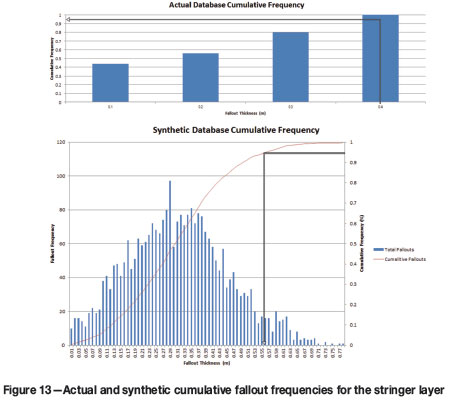
The actual database shows that for the stringer layer, a 95% fallout thickness of 0.4 m should expected, whereas the maximum experienced fallout height was 0.56 m. The synthetic database concluded that the 95% fallout height is expected to be 0.56 m with a maximum expected wedge apex of 0.77 m. This maximum expected apex height for the stringer layer is deemed more probable than that predicted for the HW1/2, as the joints are continuous in the pyroxenite and penetrate through the stringer layer.
Conclusions
► Based on the study, synthetic databases can be used to supplement the actual mine fall-of-ground database in order to build a larger database with more accurate design parameters
► Based on the results of the study and experience onmine, support design is divided into four zones, each with a specific support length and spacing in order to support 100% of the maximum fallout height expected for that specific zone
► The strategy greatly reduced the mine's fall-of-ground frequency and size, while effectively controlling support costs.
Acknowledgements
The authors wish to thank Mr J.D. Bosman for the technical review, and the Management of Two Rivers Platinum Mine for approval of the release of the information published in this paper. We also thank Mr Q. Grix for his input and data acquisition.
References
Geological Description - Geology Department. Two Rivers Platinum Mine public network, 2013. [ Links ]
FOG database - Rock Engineering Department. Two Rivers Platinum Mine -OHMS. [ Links ]
This paper was first presented at the, 6th Southern African Rock Engineering Symposium SARES 2014, 12–14 May 2014, Misty Hills Country Hotel and Conference Centre, Cradle of Humankind, Muldersdrift.

