


Services on Demand
Article
 English (pdf)
 Article in xml format
 Article references
Indicators

Related links
-
 Cited by Google
 -
 Similars in Google
Share

 Permalink
Journal of the Southern African Institute of Mining and Metallurgy
On-line version ISSN 2411-9717
Print version ISSN 2225-6253
J. S. Afr. Inst. Min. Metall. vol.114 n.10 Johannesburg Oct. 2014
6TH SOUTHERN AFRICAN ROCK ENGINEERING SYMPOSIUM
Fan-structure shear rupture mechanism as a source of shear rupture rockbursts
B.G. Tarasov
University of Western Australia
SYNOPSIS
This paper proposes the further development of a recently identified shear rupture mechanism (fan mechanism) that elucidates a paradoxical feature of hard rocks - the possibility of shear rupture propagation through a highly confined intact rock mass at shear stresses that can be significantly less than frictional strength. In the fan mechanism, failure is associated with consecutive creation of small slabs (known as 'domino blocks') from the intact rock in the rupture tip, driven by a fan-shaped domino structure representing the rupture head. The fan head combines such unique features as extremely low shear resistance, self-sustaining stress intensification, and self-unbalancing conditions. Consequently, the failure process caused by the mechanism is inevitably spontaneous and violent. Physical and mathematical models explain unique and paradoxical features of the mechanism, which can be generated in primary ruptures and segmented faults. The fan mechanism provides a novel point of view for understanding the nature of spontaneous failure processes, including shear rupture rockbursts. The process explains, in particular, features of shear rupture rockbursts such as activation at great depths, generation of new shear ruptures in intact rock mass, nucleation of hypocentres at significant distances from the excavation, shear rupture development at low shear stresses, and abnormal rupture violence.
Keywords: rock strength, failure at confined compression, shear rupture mechanism, structure of shear rupture, conditions of instability, physical model, mathematical model, shear rupture rockburst.
Introduction
It has been observed in field and laboratory conditions that failure of intact hard rocks at highly confined compression can be accompanied by abnormal violence. Under both of these conditions the failure process is associated with shear rupture development. David Ortlepp, who acquired more than 40 years of experience in the study of shear rupture rockbursts in deep and ultra-deep South African mines, emphasized this phenomenon (Ortlepp, 1997; Ortlepp et al., 2005): 'All rockbursts, by definition, involve sudden and often violent displacement of rock. Occasionally however, larger incidents cause damage of such intense violence that it seems that our knowledge of the mechanism of damage is completely inadequate.' Special field studies (Gay and Ortlepp, 1979; McGarr et al., 1979) have revealed that shear ruptures causing abnormally violent rockbursts are created in intact rock mass. An important feature is that they nucleate in zones of highly confined compression that are some distance away from excavation (on the excavation surface the minor stress is equal to zero). It was shown that these mine tremors and earthquakes share the apparent paradox of failure at low shear stresses, while laboratory measurements indicate high material strengths (McGarr et al., 1979).
Recent laboratory studies of post-peak failure of hard rocks (characterized by uniaxial compressive strength above 250 MPa) at highly confined compression (σ1 > σ2= σ3 when σ3 > 50 MPa) support Ortlepp's idea about inadequate understanding of the failure mechanism at these loading conditions (Tarasov, 2008, 2010; Tarasov and Randolph, 2008, 2011). Some observed abnormalities that cannot be explained on the basis of conventional approach are presented in Figures 1 and 2.
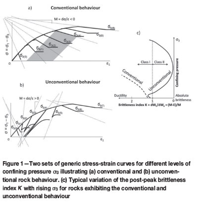
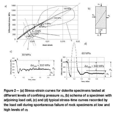
Figure 1 shows two sets of generic stress-strain curves for different levels of confining pressure σ3. Figure 1a represents the conventional (well-studied) rock behaviour associated with increasing post-peak ductility with rising σ3. For clarity, the variation of the post-peak curves is indicated by dotted lines. Figure 1b represents the unconventional type of rock behaviour. Here, increasing σ3 can lead to a contradictory variation of post-peak properties. In fact, rock behaviour can be changed from Class I to extreme Class II and then to Class I again. Class I is characterized by a negative post-peak modulus M = dσ/dЄ, and Class II by positive (Wawersik and Fairhurst, 1970). At extreme Class II behaviour, values of post-peak modulus M and elastic modulus E = dσ/dЄ can be very close, indicating extremely small post-peak rupture energy (compare shaded areas in Figures 1a and 1b for σ3 = σ3(4)).
A small post-peak rupture energy in turn indicates high post-peak brittleness. A special brittleness index was developed to characterize unambiguously the post-peak brittleness at any type of rock behaviour (see details in Tarasov and Potvin, 2013). The index K = dWr/dWe = (M - /M is based on the ratio between the post-peak rupture energy dWr and elastic energy dWe withdrawn from the material during the failure process. The index K characterizes the capability of the rock for self-sustaining failure due to the elastic energy available from the failing material. Figure 1c shows variation of the brittleness index K with rising confining pressure σ3 for rocks exhibiting conventional and unconventional behaviour. In contrast to the conventional behaviour, where increasing σ3 is accompanied by a monotonic decrease in post-peak brittleness, the brittleness variation for unconventional behaviour follows a typical pattern of initially increasing, reaching a maximum, and then ultimately decreasing. The harder the rock, the greater the effect of embrittlement. Experiments (Tarasov, 2010) showed that some rocks at high confinement became hundreds of times more brittle compared to their behaviour under uniaxial compression.
Figure 2 illustrates the abnormal violence of hard rock failure at extreme Class II behaviour. The experiments were conducted on an extremely stiff servo-controlled testing machine based upon the loading principles described in Stavrogin and Tarasov (2001). Figure 2a shows a set of stress-strain curves for dolerite (uniaxial compressive strength 300 MPa) obtained at different levels of σ3. At σ3 < 60 MPa the total post-peak control was provided for both Class I and Class II behaviour. Dotted lines here indicate general orientation of post-peak curves. At σ3 > 60 MPa control was possible only at the start of the post-peak stage, after which spontaneous and violent failure took place. Dotted lines indicate orientation of post-peak curves at the moment that instability starts. In this case M is close to E, post-peak rupture energy is vanishingly small, and post-peak brittleness approaches absolute brittleness (extreme Class II).
To demonstrate the difference in violence at spontaneous failure for Class II at low σ3 (where post-peak control is possible) and for extreme Class II at high σ3 (where post-peak control is impossible), some special experiments were conducted. At low σ3 the spontaneous failure was generated at the peak stress due to the absence of post-peak servo-controlling. During failure at all levels (low and high) of σ3 the differential stress variation with time was recorded by a load cell adjoining the tested specimens (Figure 2b). Two different modes of rock behaviour were distinguished. Figure 2c shows a stress-time curve typical for σ3 < 60 MPa, while Figure 1d shows a stress-time curve typical for σ3 > 60 MPa.
It should be emphasized that for the two curves obtained at σ3 = 30 and 60 MPa the stress drop Δσ (the difference between the stress of the instability start σA and the residual strength σf) was practically the same: Δσ(30) = 310 MPa and Δσ(60) = 340 MPa. Points of instability are marked by asterisks on the stress-strain curves in Figure 2a and stress-time curves in Figures 2c and 2d. Despite the fact that the elastic energy available from the specimen-loading machine is comparable for both experiments, the shapes of the curves differ dramatically. For σ3 = 30 MPa the failure was followed by a conventional stress oscillation around the residual strength. For σ3 = 60 MPa an extraordinary post-failure stress shock was generated, after which the equilibrium condition was reached at a stress level significantly below the residual (frictional) strength σf. Identical stress shocks were observed in all experiments conducted at σ3> 60 MPa (Tarasov and Randolph, 2008).
The observed features of hard rocks, such as the dramatic post-peak embrittlement with rising confining pressure σ3; the abnormal failure violence within a certain range of σ3; and the huge after-failure stress-shock cannot be explained according to the basics of common understanding of shear rupture mechanisms. This paper shows that the observed abnormalities are generated by a recently identified shear rupture mechanism (fan mechanism) that is activated in hard rocks (uniaxial compressive strength above 250 MPa) at highly confined compression. In the fan mechanism, the rock failure is associated with consecutive creation of slabs (known as 'domino blocks') from the intact rock in the rupture tip and is driven by a fan-shaped domino structure representing the rupture head. The fan head combines such unique features as extremely low shear resistance, self-sustaining stress intensification, and self-unbalancing conditions. Consequently the shear rupture can propagate through the medium with negligible resistance, resulting in abnormal violence. Physical and mathematical models of the mechanism presented in this paper explain the unique and paradoxical features of the mechanism. This mechanism can operate in small laboratory specimens and in field conditions, causing shear rupture rockbursts and earthquakes. Natural faults normally have a very complicated multi-hierarchical segmented structure. We will firstly discuss features of the fan mechanism operation in primary ruptures (thin continuous formations), and then in complex faults (Ortlepp shears).
Fan mechanism in primary ruptures
Frictional and fan-hinged shear
This section discusses the interrelation between well-known failure mechanisms for rocks at confined compression and the fan mechanism. It is known that rock failure mechanisms are dependent on the level of confining pressure σ3(e.g. Kirby and McCormick, 1984). Figures 3a and 3b show variations in failure mechanisms, with σ3 rising from left to right, for rocks exhibiting conventional and unconventional behaviour. Rectangles represent rock specimens exhibiting different failure mechanisms. In brittle rocks, pre-existing defects at loading generate tensile cracks, the ultimate length l of which is a function of σ3, as shown symbolically by dotted lines: the higher the σ3 the shorter l. The length l of tensile cracks in turn determines the macroscopic failure mechanism and the failure pattern.
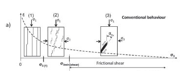
At confining pressures σ3 < σ3min(shear), shear rupture cannot propagate in its own plane due to the creation in the rupture tip of relatively long tensile cracks preventing the shear rupture development. The tensile cracks grow along the major stress. Two failure mechanisms distinguished at these stress conditions are: (1) splitting by long tensile cracks and (2) failure due to coalescence of distributed micro-cracks accumulated within the material body during loading.
At σ3> σ3min(shear) the failure mode is localized shear. Due to high confinement, micro-tensile cracks become sufficiently short to cause shear rupture to propagate in its own plane. Here the dilation of one short micro-crack induces the dilation of a closely spaced neighbouring crack (Reches and Lockner, 1994). Due to the consecutive creation of short tensile cracks in front of the rupture tip, the advancing fault itself induces organized damage that is restricted to its own plane. It is important to note that micro-cracks are generated along the major stress, which is at angle αo ≈ (30°-40°) to the shear rupture plane (Reches and Lockner, 1994; Horii and Nemat-Nasser, 1985). This micro-cracking process creates inclined intercrack blocks (known as domino blocks) which are subjected to rotation at shear displacement of the rupture interfaces (Peng and Johnson, 1972; King and Sammis, 1992; Reches and Lockner, 1994). Two specific shear rupture mechanisms have been distinguished here.
Frictional shear
The development of a frictional shear rupture can be controlled on stiff servo-controlled testing machines. It has been observed that intercrack domino blocks generated in the rupture tip are subjected to collapse at rotation caused by shear displacement of the rupture faces, creating frictional structureless medium (gouge) in the shear rupture interface (Peng and Johnson, 1972; King and Sammis, 1992; Reches and Lockner, 1994). Increasing confining pressure (σ3 in this case) increases friction within the total rupture zone (including the rupture head), which causes the increase in post-peak rupture energy according to the conventional rock behaviour shown in Figure 1a.
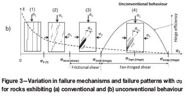
Fan-hinged shear
It should be noted that the three mechanisms discussed are activated in practically all types of rock. The fourth mechanism is generated in hard rocks (characterized by uniaxial compressive strength above 250 MPa) and is responsible for the unconventional behaviour (Tarasov, 2008, 2010). Further increases of the confining pressure above σ3 = σ3min(shear) will continue reducing the length l of tensile cracks (dotted curve in Figure 3b) and, consequently, the length of domino blocks composing the fault structure. Due to the very strong material and proper geometry of short domino blocks within the range σ3min(hinge) < σ3 < σ3max(hinge) they can withstand rotation caused by the shear displacement of the rupture faces without collapse. In this case the domino blocks behave as hinges, and due to consecutive generation and rotation they create a fan structure representing the shear rupture head. The fan structure has several extraordinary features which will be discussed further.
It should be emphasized that the efficiency of the fan mechanism is variable and determined by how perfect the fault structure is. The solid curve in Figure 3b shows symbolically the variation of the fan mechanism efficiency versus confining pressure, which determines the identical variation of post-peak brittleness of rocks exhibiting unconventional behaviour (see Figure 1c). At the low end of the hinge pressure range, when the relative length (length/thickness) of the rotating blocks is still large, the domino blocks are subjected to partial destruction (buckling) as they rotate (the role of block geometry is discussed in more detail later). At higher σ3, with shorter blocks, this imperfection decreases, rendering the fan mechanism more efficient. The optimal efficiency takes place at a confining pressure at which the blocks rotate with minimum destruction. At greater σ3 the efficiency reduces because shorter blocks gradually lose any potential to operate as hinges. Finally, very short blocks lose this capability completely and the rock behaviour returns to the commonly accepted frictional mode.
Physical model of the fan mechanism
Self-balancing fan structure
As discussed above, primary shear ruptures propagate through rocks due to the consecutive formation of identical domino blocks from the intact material in the rupture tip. Further rotation of the blocks between the shear rupture faces can lead to frictional shear (at block collapse) or to fanhinged shear (at block rotation without collapse). The mechanism responsible for the creation of identical domino blocks is not considered in the physical and mathematical models presented in this paper. The models discuss the influence of the fan structure formed on the basis of rotating blocks on the rupture process. In the models the domino blocks are considered as 'predetermined' and operating with optimal efficiency (without collapse at rotation).
Photographs of the physical model in Figure 4a show different stages of fan formation. At the initial condition (Figure 4a-I) a row of identical domino blocks inclined at angle α0 represents an implicit horizontal shear rupture (fault). Surfaces of neighbouring domino blocks are in full contact, providing a very compact 'monolithic' material. To simulate the resistance of domino blocks to tearing-off from the monolithic material (which takes place in real materials) the blocks are bonded to each other. The row of domino blocks is located between two layers of elastic material (elastic connectors) representing the fault interfaces. The upper and lower elastic connectors are fixed to corresponding ends of each domino block. Contact areas between the ends of domino blocks and the interfaces we will call joints. As such, a version of the model with bonded blocks can be treated as representing an intact material. Evenly distributed weight located on the upper layer creates normal stress applied to the simulated fault αn = αp.
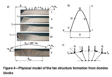
Propagation of shear rupture along the potential fault can be initiated by application of a local force F to the elastic connector fixed to the top of the first domino block (Figure 4a-II). The applied force will be transmitted to the next blocks by stretching elastic connectors between them at the consecutive separation of blocks and rotation of them against joints. Due to this, the domino blocks will be sequentially (one by one) torn off from the 'monolithic' material, forming a fan-shaped structure. The fan has completed when the front block rotates on the total angle βtot = 180° - 2α0 at shear displacement Δ of the rupture faces. The total number of domino blocks involved in the fan structure of the physical model is about 30, while in real materials it can be thousands (Tarasov and Guzev, 2013). The fan structure with small number of domino blocks in the physical model will allow some features of the fan mechanism to be illustrated more legibly.
Figure 4b reflects experimentally determined variation of the force F applied to the first domino block during fan formation and, consequently, the variation of shear resistance of the fan structure at different stages of its formation. Such variation of the shear resistance is determined by the fact that elementary forces N (representing normal stress σn) applied to each domino block create horizontal components fN of opposite directions in the first and the second half of the fan structure (Figure 4c). Due to this, the maximum resistance is attained at the completion of the first half of the fan, while the totally completed fan structure represents the self-balancing structure with shear resistance equal to zero (details are given in the mathematical model presented later).
Shear resistance below the frictional strength - pulse-like rupture mode
To make the fan structure self-unbalancing, a distributed shear stress τ should be applied to the whole domino row. The simplest way to apply the distributed shear stress for the physical model is to incline the row by angle γ as shown in Figure 5a. The distributed weight σp in this situation creates shear stress τ = σpsinγ along the whole structure. Under the effect of distributed shear stress the fan propagates along the whole row, sequentially moving the loaded upper face against the lower one by distance Δ.
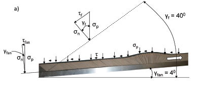
Experiments on the physical model show that the minimum angle γ at which the fan becomes unstable is about 4°. The distributed shear stress generated at this angle is just sufficient to overcome the shear resistance of the fan structure, which is determined by (1) friction in joints of rotating domino blocks and (2) the reduced resistance associated with the tearing off of each front domino block from the intact material. It was established that the resistance to shear provided by the fan structure is very low. To move the same fault faces at common frictional resistance (without fan structure) the angle γ should be about 40°. This experiment clearly demonstrates that shear resistance of the fan structure τfan can be significantly less than the common frictional strength τf. For this particular model, shear resistance (strength) of the fan structure τfan is less than the frictional strength τf: τfan ≈ 0.1τf by a factor of ten.
It should be emphasized that low shear resistance is encountered within the zone of the moving fan head only. In front of the fan the material is in an intact condition. Behind the fan, shear resistance is equal to friction. Due to this the fan mechanism provides the pulse-like rupture mode: at any given time during rupture propagation, slip occurs over only a narrow band (fan head) along the fault and the fault relocks behind the rupture head. This slip pulse propagates forward as the fault proceeds. Pulse-like rupture mode was observed for earthquakes (Healton, 1990) and in laboratory (Ohnaka et al., 1986; Lykotrafitis et al., 2006).
Conditions of fan nucleation and propagation
Figure 5b illustrates schematically the most important feature of the fan mechanism. Horizontal lines show different strength levels along a hypothetical fault zone: τu - strength of intact material (fracture strength); τf - frictional strength of pre-existing fault; τfan - strength (shear resistance) of the fan structure. The graph on the left reflects the procedure of fan mechanism activation as discussed in Figure 4a. To create the initial fan structure a local stress equal to the fracture strength τu should be applied. The development of the initial fan structure is a stable process. After completion of the fan head, further dynamic propagation of the fault through the intact material can occur at any distributed shear stresses exceeding the fan structure strength τfan. New faults in intact materials can thus be produced by the fan mechanism even at distributed shear stresses that are significantly below the frictional strength τf (this will be discussed in more detail further). At the same time, the higher the distributed shear stress applied the higher the rupture speed and rupture violence.
Mathematical model of the fan mechanism
Interaction of domino blocks and self-balancing conditions
Further elucidation of the fan mechanism will be provided in this section on the basis of the mathematical model (further development of the model by Tarasov and Guzev, 2013). The mathematical model here represents the simplest description of the fan mechanism and reflects the static balance of forces affecting the domino structure before instability. This model was designed to demonstrate the essence of the fan mechanism, including some extraordinary features (e.g. self-balancing principle, extremely low shear resistance, self-sustaining stress intensification, self-unbalancing conditions). All simplifications made in the model do not distort the essence of the fan mechanism.
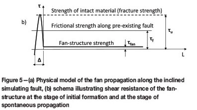
The domino structure of the mathematical model has the same features discussed for the physical model. For simplicity we will discuss the domino blocks as shown in Figure 6a. All blocks here are represented by beams of length r inclined at the initial angle α0 and distanced from each other by s. The distance is s = w/sinα0, where w is the block width. Both ends of each beam are connected to the upper and lower layers by joints. For ease we assume that the upper layer is represented by an elastic material, while the lower layer and the beams (domino blocks) are stiff. As such, a version of the model with blocks bonded together can be treated as representing the intact material.
Evenly distributed normal σn and shear τ stresses are applied to this construction. The value of τ is less than the shear stress necessary for displacement of the upper layer against the lower. Each beam is loaded by the same normal, N, and horizontal (shear), fτ, elementary forces representing the evenly distributed normal σn and shear τ stresses applied to the whole structure. Elementary forces N (and their horizontal components) are shown by black arrows. Elementary forces fτ are shown by red arrows. The meaning of the elementary forces is as follows: N = σns1; Fτ = τs1, where depth (or thickness) of the model is equal to unity. It should be noted that in the completed fan structure, due to stretching of the interface the distance between any two neighbouring blocks on one side of the fan increases (compared to the initial distance s) and the interface acquires a wave-like shape, which should affect the values of stresses (σn, τ) and elementary forces (N, fτ). To simplify the model we will consider the applied stresses and elementary forces invariable. This simplification does not affect the equilibrium condition of the completed fan and the extraordinary features of the fan-structure, which we shall demonstrate, thanks to the symmetrical configuration of the fan structure.
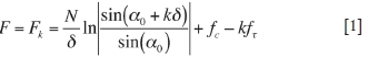
The fan structure can be formed if, in addition to the existing evenly distributed stresses, a local supplementary force (or stress) is applied. Let us apply a supplementary horizontal force F to the upper end of the leftmost beam. Figure 6b shows an intermediate stage of the fan formation. Equation [1] describes a variation of shear resistance (F) during formation of the fan structure (see details in Tarasov and Guzev, 2013).
where
fc is the reduced resistance of tearing off the front beam from the basis (the elementary force fc is applied to the front beam only and shown by a green arrow in Figures 6b)
k is the number of activated beams
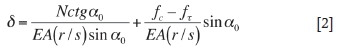
δ is the average angle between two neighbouring beams described by Equation [2] (Tarasov and Guzev, 2013).
where
E is the modulus of elasticity of the elastic connector
A is the cross-sectional area of the elastic connector.
An essentially important feature of the fan structure is the fact that the resistance fN = N/tgα(see Figure 6b) of each beam decreases with increasing angle α from α0. It reaches zero at α = 90° and becomes negative at α > 90°. This means that the formation of the first half of the fan structure is accompanied by the increase in shear resistance F; it reaches a maximum when the half of the fan has completed and then decreases to zero, similar to the experimental graph in Figure 4b.
Self-sustaining stress intensification and conditions of instability
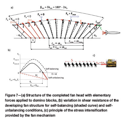
Figure 7 illustrates some features of the completed fan structure. In Figure 7a, elementary forces resisting displacement of the top rupture face against the bottom one are directed to the right, while forces assisting displacement are directed to the left. Shear resistance of relative displacement of the rupture faces due to the fan mechanism is determined by the sum of all horizontal forces applied to all beams involved in the completed fan, which is represented by Equation [3].
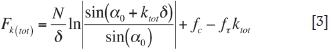
The first term of Equation [3] reflects the effect of elementary forces fN = N/tgα and elastic forces associated with stretching of the elastic connectors on shear resistance of the fan structure. The elastic forces are represented here by angle 5. At self-balancing conditions the elastic forces are neutralized by forces fN. For the completed fan structure α0+ ktotδ = - α0,, which means that the first term of Equation [3] is equal to zero.
The second term of Equation [3] reflects the reduced resistance fc of tearing off the front beam (domino block) from the intact material. The elementary force fc (green) is applied to the front beam only. It will be shown that the contribution of fc to the total resistance of the fan structure in real rocks is negligibly small.
The third term of Equation [3] represents an active united force assisting displacement. It is caused by the evenly distributed shear stress τ applied to the material. It should be emphasized that, unlike fc, the elementary forces fτ (red) are applied to all ktot beams of the fan structure.
When τ = 0 the formation of completed fan structure can be conducted in a stable regime using stiff +servo-controlled loading principles. Dotted beams in Figure 7a correspond to positions of them for the self-balancing fan. The dotted black curve in Figure 7b illustrates the variation of the fan head resistance Fk at the fan structure development for the self-balancing condition. The horizontal axis represents the fan structure length l = sk.
With distributed shear stress (τ > 0) the fan head becomes self-unbalancing and starts propagating through the intact material. Separation (tearing-off) of the front domino blocks sequentially from the intact material is the essence of the failure process created by the fan mechanism. It should be emphasized that the fan structure in this case represents a natural stress intensifier that magnifies stresses in the rupture tip providing the tearing-off process. Elementary horizontal forces fT (red) applied to each domino block of the fan as shown in Figure 7a are transmitted via the elastic connector (interface) to the rupture tip by the principle shown in Figure 7c. Hence, the separation of each front domino block with the reduced resistance fc (green arrow) from the intact material is caused by the united active force ktotfτ where ktot is the total number of domino blocks in the fan head. Calculations by Tarasov and Guzev (2013) show that the fan structure in natural materials can incorporate thousands of domino blocks Hence separation of the front domino block from the intact material can be caused by very low shear stress applied fτ =fc/ktot. The contribution of fc c to shear resistance of the fan structure is therefore negligible due to intensive stress magnification in the rupture tip caused by the fan mechanism.
The solid curve in Figure 7b shows features of the fan formation for the case when τ > 0. At the initial stage of the fan formation F k increases; it reaches a maximum F k = F max, then decreases to zero Fk = 0, and finally becomes negative Fk < 0. At the last stage (after point A) the fan formation is inevitably unstable because internal forces within the fan structure are not equalized and the fan head starts moving spontaneously as a wave. Depending on the value of distributed shear stress applied the extreme situation, Fk = 0 can be reached at different stages before the completion of the fan structure.
Effect of friction in joints and block collapse on shear resistance of the fan structure
The analysis of the idealized fan model (without friction in joints of rotating domino blocks) shows that the shear resistance of the completed fan structure propagating through the intact material is negligibly small. If we take into account friction in joints, we can estimate the real shear resistance of the fan structure. Estimations by Tarasov and Guzev (2013) show that despite friction in joints, shear resistance between two interfaces separated by the fan structure of domino blocks operating as hinges is lower than the frictional strength of pre-existing faults with common frictional interfaces by the ratio w/r. Here, w is the width and rk is the length of domino blocks (see Figure 6a). The shear resistance associated with friction in joints represents the total resistance of the fan head propagating through the intact material:

Equation [4] shows that increasing the ratio r/w decreases the effect of friction in joints on the fan shear resistance: the higher the r/w the greater the efficiency of the fan mechanism. As discussed previously, the length of domino blocks is a function of confining pressure σ3 (dotted line l versus σ3 in Figure 3b). By analogy, the dotted line in Figure 8a shows symbolically the variation of the ratio r/w versus o3 within the pressure range between σ3min(shear) and σ3max(hinge). This line indicates the hinge efficiency variation with confining pressure if domino blocks are not collapsed at rotation.
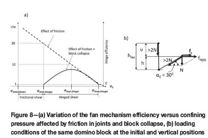
It should be noted that each block in the fan functions similarly to a beam with rotation-free end conditions loaded along the beam axis. Figure 8b illustrates features of the axial loading of a block at the initial (α0 = 300) and vertical positions. It shows that the value of axial force applied to the front domino-block exceeds the elementary force N (associated with the evenly distributed normal stress σn) by more than two times. This force is determined by forces N and fc. It means that any block at the front position is in the most stressed conditions. If the block does not collapse at the start of rotation it will be capable of bearing identical stresses at any stage of its rotation, including the vertical position when it deforms the rupture faces by the value µ. All blocks of the fan in combination create additional normal stresses moving apart the fault faces (wedge effect). We can suppose that during rotation from the initial to the final position, each domino block of the completed fan structure is under approximately the same axial stresses.
In rocks under confined compression, domino blocks are subjected to high loads that can lead to buckling and collapse of the blocks. On the basis of information presented by Megahid et al., (1993) we assume that domino blocks with slenderness ratio r/w < 10 are stable at axial loading. Domino blocks with slenderness ratio r/w > 10 will be subjected to different degrees of destruction, depending on the ratio r/w. The solid graph in Figure 8a illustrates a possible variation of the fan mechanism efficiency versus confining pressure σ3, taking into account the block destruction. At values r/w < 10 the efficiency varies in accordance with Equation [4]. Within the range 10 < r/w < 20, due to different degrees of destruction (depending on r/w) only a part of each block can maintain stability operating as a hinge. Very long blocks with slenderness ratio r/w > 20 completely collapse at rotation, creating gouge and common friction between the interfaces. This is a preliminary explanation for the variable fan mechanism efficiency. Further experimental and theoretical studies will allow better understanding of this phenomenon.
The important point is that the fan mechanism is active only within the range of confining pressure between σ3min(hinge) and σ3min(hinge), with optimal efficiency at σ3opt(hinge). Such variation of the fan mechanism efficiency causes corresponding variation of the unconventional rock behaviour (e.g. brittleness variation shown in Figure 1c). In accordance with Equation [4], the shear resistance (strength) of the fan head for domino blocks characterized by the ratio w/r = 0.1 is one-tenth of the frictional strength: τfan ≈ 0.1τf. This estimation is consistent with the result obtained on the physical model.
Uncontrollable failure and abnormal violence caused by the fan mechanism
In this section we discuss an energy balance at spontaneous failure of rock specimens caused by the fan mechanism. It should be noted that loading conditions to generate the fan mechanism in rock specimens are different from those in the physical model discussed previously. In the physical model the fan structure was generated by a stress applied locally. Rock specimens tested at highly confined compression are small. In order to generate the fan structure in this situation the whole specimen has to be loaded axially to high stresses that correspond to the material strength. Let us analyse features of the failure process caused by the fan mechanism at such stress conditions.
We will do this on the basis of experimental results obtained on the dolerite specimen tested at confining pressure σ3 = 60 MPa (Figure 2). The same stress-displacement curve is shown in Figures 9a and 9b. Point A beyond the peak stress on these graphs corresponds to the start of instability. Figure 9c shows an enlarged portion of the post-peak stress-strain curve at stress degradation from ultimate stress σu till σA (this is replicated four times). At this post-peak stage the rupture was easily controllled. However, below σA (points A) control became impossible. To analyse the reason for that we divided the post-peak curves into four stages with equal intervals of differential stress. Each stage is characterized by average values of elastic modulus E (solid lines) and post-peak modulus M (dotted lines). Areas located between the E and M lines indicate the current post-peak rupture energy dWr:
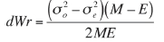
Here σ0 and σe are differential stresses at the onset and the end of each stage.
We can see that the current post-peak rupture energy decreases dramatically with the rupture development from stage 1 to stage 4. The variation of dWr with stress degradation from σu to σA is illustrated in Figure 9d. At stage 4 the rupture energy becomes extremely small because modulus M approaches modulus E. Such variation in the post-peak rupture energy can be caused by the formation of the second half of the fan structure as was shown for the physical model on the graph in Figure 4b. After completion of the fan structure the uncontrollable spontaneous failure starts due to the high distributed shear stress (corresponding to point A on the diagrams in Figures 9a and 9b).
Figure 9e illustrates features of the shear rupture propagation through the specimen after the fan structure has completely formed. Figure 9e (1) shows the situation corresponding to point A, after which the fan head started propagating spontaneously along the dotted line. Figure 9e (2) shows an intermediate situation where the rupture is propagating in the pulse-like mode. Shear resistance and displacement along the fault during the failure process are very irregular. Three specific zones can be distinguished: (1) the fan zone where the failure process and domino block rotation is in progress; (2) the frictional zone located behind the fan head where the blocks have completed their rotation and the full friction is mobilized; and (3) the intact zone in front of the fan head. A load cell and an axial gauge in Figure 9e (1) mounted on the specimen as is commonly used in experiments can measure only the average load-bearing capacity and displacement of the specimen during the failure process. Results obtained on the basis of these gauges do not allow estimating the real energy balance of the failure process. However, the new knowledge about the fan mechanism gives us a chance to derive this inaccessible information.
The red area in Figure 9a represents elastic energy accumulated within the specimen and the machine at point A at the moment of the instability start (AD is the loading stiffness). At point A the bearing capacity of the specimen measured by the load cell (axial stress σA) is generally provided by the intact material located in front of the fan head. The contribution of the fan head to the bearing capacity of the specimen is very small. Starting from this moment, the fan head with resistance σfan crosses the specimen. Axial displacement dfan of the specimen caused by this process is associated with rotation of domino blocks as shown in Figure 9f. For the fault thickness h = 0.1 mm and α0 = 30° the displacement dfan ≈ 0.3 mm. Due to a very small shear resistance of the fan head (assume σfan ≈ 0.1 σf) the post-peak rupture energy Wr(fan) associated with failure and displacement by the distance dfan ≈ 0.3 mm is also very small. Wr(fan) is represented by the grey area in Figure 9b. After the fan head has crossed the specimen, displacement along the whole fault becomes possible. This displacement is accompanied by violent dynamics caused by a large amount of released energy Wa (yellow area in Figure 9b). Shear resistance of the fault at this stage is determined by frictional strength σf.
Due to the inertia associated with high dynamics, the total displacement along the fault dtot will exceed the coordinate of point B corresponding to frictional (residual) strength σf. The equilibrium conditions will be reached below σf at point B1 (see Figures 9b and 2d). The violent displacement along the fault will pulverize the initial domino structure and create gouge between the fault interface at the final stage of the failure process (Figure 9e (4)).
It should be emphasized that during spontaneous failure after point A, self-unbalancing conditions exist within the fan head at any level of stresses above σfan. This means that stable and controllable failure beyond point A is in principle impossible for the fan mechanism, even on an absolutely stiff and servo-controlled testing machine. This explains the absence of experimental post-peak data for hard rocks at highly confined conditions (Mogi, 2007; Shimada, 2000; Tarasov, 2010). High rupture speed and pulverization of the initial fault structure during the spontaneous failure process make it impossible to directly observe and study the fan mechanism, and this explains why the mechanism has not been detected before.
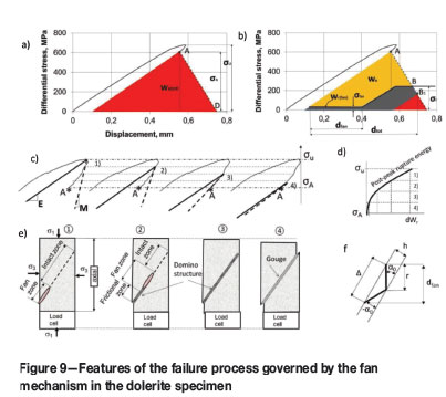
Figure 10 explains the post-failure stress-shock discussed in Figure 2d by comparing different failure regimes (frictional shear and fan-hinged shear) with sliding a board along a hillside. When friction is constant during the dynamic events as shown in Figure 10a, the failure and sliding processes are not accompanied by stress shock. However, if low friction is suddenly substituted by high friction, the stress shock becomes inevitable (Figure 10b).
Fan mechanism in natural faults
Structure and evolution of Ortlepp shears
Natural faults normally have very complicated structure. Before elucidating the role of the fan mechanism in the formation of dynamic natural faults, we will discuss features of complex fault development. Different hypotheses of fault evolution have been proposed (Segall and Pollard, 1980; Sibson, 1982; Scholz, 2002; De Joussineau and Aydin, 2009), but there is still no consensus regarding this process. This section introduces a possible version of fault evolution based upon studies of: (a) faulting process at highly confined compression in laboratory experiments on calcareous siltstone (Otsuki and Dilov, 2005) and (b) structure of dynamic faults in rockbursts generated by shear rupture in brittle quartzite in deep South African mines (Ortlepp, 1997).
Experiments conducted by Otsuki and Dilov (2005) demonstrated the following features of complex faults:
(1) Faults are multi-hierarchical segmented formations
(2) Segmentation as a mechanism of fault propagation acts on all hierarchical ranks of complex faults
(3) Segmentation is a result of advanced triggering of a new bilaterally propagating rupture (new segment) in front of the propagating current rupture (current segment)
(4) The current and new segments propagating toward each other form a jog (step) where they meet
(5) Jogs of a compression type are very common in fault zones regardless of their size
(6) Once a number of segments of a given hierarchical rank coalesce, they behave as a single new and longer segment of one higher rank
(7) Segment of higher rank can trigger a new segment (rupture) at greater distance
(8) The new triggered segment starts as a primary rupture.
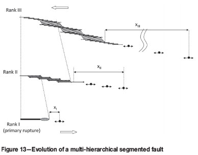
All these features are illustrated and discussed briefly below. The series of photographs in Figure 11a shows principles of the fault evolution by the advanced triggering of new segments (modified from Otsuki and Dilov, 2005). Segments are represented here by white lines. The fault propagates from left to right. The segments are generated one by one and propagate bilaterally. Neighbouring segments are connected by a compressive jog where they meet. Overlap zones of the jogs are subjected to significant irreversible deformation. Figure 11b shows features of compressive jogs formed in brittle quartzite (photographs from Ortlepp, 1997). The overlap zones of these jogs are represented by a row of domino blocks.
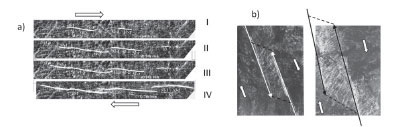
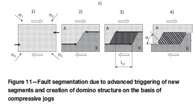
Figure 11c proposes a possible mechanism of the domino structure formation in compressive jogs (Tarasov and Ortlepp, 2007). It shows four steps of linkage between two segments (bold arrows) propagating towards each other in intact rock. Figure 11c (1) indicates the directions of the applied stresses against the propagating segments. In Figure 11c (2) the rock mass surrounding the approaching segments is theoretically divided into two massive blocks (A and B) pressed against each other by the applied stresses. The propagation of the segments decreases shear resistance between the massive blocks along these segments, which overstresses an area located between the tips of the approaching segments (Segall and Pollard, 1980). With further propagation of the segments they confine a zone that is now overstressed (Figure 11c (3)). When the extending overlap zone in hard brittle rocks reaches a critical length it fractures dynamically into an echelon of domino blocks (slabs) due to the shear of the overlap zone between the parallel faces of the massive blocks A and B (Figure 11c (4)). This process is accompanied by the release of some portion of elastic energy. After that the segments stop propagating. The initial orientation of the tensile cracks separating the overlap zone into domino blocks is parallel to the major stress σ1. By analogy with primary ruptures angle αo ≈ (30°-40°). In contrast to primary ruptures where the domino blocks are generated sequentially in the rupture tip, this mechanism generates a row of parallel domino blocks simultaneously within the overlap zone of compressive jogs.
This mechanism can create cascades of compressive jogs which in combination can represent a fault segment of higher hierarchical rank. Figure 12 illustrates the principle of formation of a multi-segmented fault, a photograph of which is shown on the right. The fault propagates upwards. Open arrows indicate the direction of applied shear stress. At stage I a dynamically propagating primary fracture triggers an advanced fracture. Asterisks indicate centres of initiation of advanced triggered fractures. This new fracture (as well as all further triggered fractures) propagates bilaterally towards the current fracture and in the opposite direction. This fracture in turn triggers the next advanced fracture shown at stage II. At this stage the overlap zone between the two bottom fractures has reached the critical length and divided into a row of domino blocks. Further fault development occurs through repetition of similar stages. In Figure 12 new compressive jogs adjoining the tip of propagating fault are shown in red.
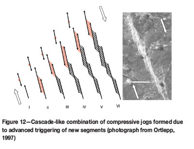
Figure 13 shows the evolution of a multi-hierarchical segmented fault. The fault nucleates as a primary rupture (bottom left corner) because the fan mechanism mobilized in very thin primary ruptures is the most energy-efficient shear rupture mechanism. A new primary rupture can be triggered in front of the current one at a distance xI due to stress transfer. Primary ruptures represent segments of rank I. Once a number of segments of a given hierarchical rank coalesce, they behave as a single new and longer segment of one higher rank. The rank II segmented rupture can trigger a series of new primary ruptures at different distances with maximum remoteness of xII. The key feature of fault segmentation is the fact that a new segment triggered by the current segment of any rank nucleates as a primary rupture. At its propagation towards the current segment (and in the opposite direction) the new segment will be subjected to similar evolution as the current segment. After linkage of a number of rank II segments the next rank III segment will be formed (shown on a smaller scale ≈ 1:5). Further development of this fault will be accompanied by creation of higher rank segments. Where they meet, segments of each hierarchical rank form compressive jogs and domino structures of corresponding rank.
Formation of the fan structure in segmented faults
The photographs in Figure 14a (from Ortlepp, 1997) demonstrate that domino blocks involved in complex faults can be subjected to rotation by angle β due to shear displacements of the fault faces. Observations show that angle β can be relatively high, exceeding 90°. Taking this fact into account we can suppose that during the fault propagation, domino blocks within a set of compressive jogs representing the fault head can created a fan-shape structure as shown symbolically in Figure 14b due to rotation of domino blocks through different angles β caused by the variable shear displacement along the fault. In the front jog the block orientation is α0. The final block position at the end of the fan head is (-α0). The segmented fan structure has the same remarkable features as discussed for primary ruptures.

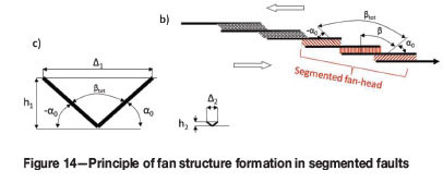
It should be emphasized that the fan structure can be formed if shear displacement between the fault faces is sufficient for the completed block rotation. Figure 14c shows the initial and final position of domino blocks for two shear ruptures of thickness h1 and h2. The thick rupture requires significantly greater displacement Δ to complete the block rotation. Equation [5] allows estimation of the fault displacement Δfauit necessary for creation of the fan structure:

Taking this into account, we can analyse the possibility of the fan mechanism activation in a complex fault shown in Figure 15 (photograph from Ortlepp, 1997). The structure of this fault is shown symbolically on the left. It includes primary ruptures and higher rank segments formed on the basis of compressive jogs (rank II and rank III). Ortlepp (1997) indicates that the magnitude of the jog (or step) of rank III is hIII = 260 mm. The magnitude of shear displacement along the fault is less than 100 mm. This means that the fan structure cannot be formed on the basis of domino blocks of rank III. However, the development of primary ruptures (rank I) and ruptures of rank II can be governed by the fan mechanism because for these Δfault ≥ Δfan.
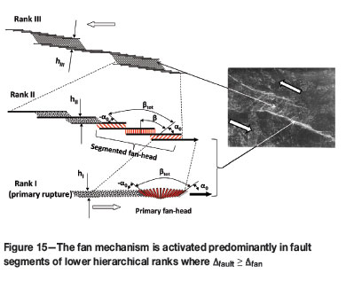
Due to this, the self-unbalancing fan structure (red zones in Figure 15) is created predominantly in segments of lower ranks. The fan mechanism generated here is responsible for high dynamics of the failure process. Relatively thin localized zones of very intense destruction can be observed in each dynamic fault. The initial domino structure of these segments is completely destroyed by extensive and violent shear and represented by pulverized gouge or even by pseudo-tachylytes. This explains why the fan structure has never been seen in nature, unlike domino structures of high-rank segments observed in a myriad of different faults. In high-rank segments, domino blocks rotate through low angles without destruction and serve as a dampening mechanism.
Nucleation and propagation of dynamic natural faults
The analysis of the physical and mathematical models shows that the initial formation of the fan structure requires a high local shear stress corresponding to the material's fracture strength tu. After that the fan head can propagate dynamically through intact rock mass at shear stresses below the frictional strength. It is known that the field stress in the lithosphere cannot exceed the frictional strength. However, local stresses in the intact rock mass in the vicinity of preexisting discontinuities (e.g. boundaries between tectonic plates, faults, deep mines, etc.) can reach the fracture strength levels tu. According to the new approach, preexisting discontinuities act as stress concentrators creating the starting conditions for the fan mechanism, but instability (e.g. earthquakes) occurs due to the development of new faults in the intact rock mass.
Figure 16 illustrates this feature. Figure 16a shows a fragment of the rock mass with the local zone of high shear stress adjoining a pre-existing discontinuity where the fan structure is generated and a large zone of lower stress where the fan head can easily propagate. In Figure 16b the red graph illustrates shear resistance of the fan head at two stages: nucleation (length of fan head fracture lfan, strength τu) and propagation (length of created shear fracture L >>> lfan, strength τfan). The horizontal dotted line shows the level of frictional strength τf. The horizontal bold line corresponds to the field stress level τ.
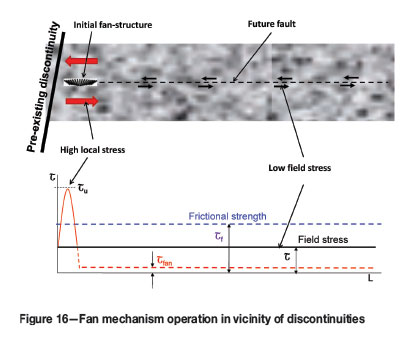
Paradoxically, the low strength of intact rock provided by the fan mechanism favours the generation of new faults in an intact rock mass over reactivation of pre-existing faults (Tarasov, 2013). This unique feature of the fan mechanism allows the supposition that the majority of dynamic events in the Earth's crust result from generation of new faults. However, the proximity of pre-existing discontinuities to the area of instability caused by the fan mechanism creates the illusion of stick-slip instability on pre-existing faults, thus concealing the real situation.
Generation of shear rupture rockbursts by the fan mechanism
The fan mechanism could be responsible for some types of man-made earthquakes. Special studies conducted in South African mines (Gay and Ortlepp, 1979; McGarr et al., 1979) show that shear rupture rockbursts, which are seismically indistinguishable from natural earthquakes, are generated in intact hard rock (dry quartzite) in zones of highly confined compression. It was shown that these mine tremors and earthquakes share the apparent paradox of undergoing failure at low shear stresses, while laboratory measurements indicate high material strengths.
Figure 17 shows a cross-section of the Earth's crust involving an opening. The graph on the left illustrates variation of minor stress σ3 with depth. The fan mechanism can be activated below a critical depth corresponding to the critical level of minor stress a3min(hinge) in Figure 3b. The zone of fan mechanism activity in Figure 17 is shown by the grey area. The efficiency of the fan mechanism increases with increasing brittleness of the rock with depth. However, around the opening the minor stress is below the critical level σ3 < σ3min(hinge). The dotted areas in Figure 17 show zones where the fan mechanism cannot be generated.
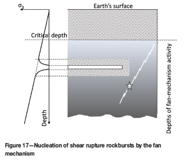
Deep openings similar to any pre-existing discontinuity represent stress concentrators. If locally elevated shear stresses in the grey area reach the level of ultimate stress tuτu (see graph in Figure 16) the fan head will be generated in the intact rock mass distanced away from the opening. After that the fan head can propagate further spontaneously through the zone of lower shear stress, creating new shear rupture and resulting in a shear rupture rockburst.
The fan mechanism is generally activated in intact rocks. However, pre-existing faults can also be reactivated by the fan mechanism under special conditions. Seismic data and geological observations suggest that faults strengthen (heal) during the inter-seismic period of the earthquake cycle due to metamorphism and intruding igneous rocks. When the structure of the healed fault becomes strong enough for the creation of domino blocks capable of rotating without collapse, it can be reactivated by the fan mechanism. The fan mechanism cannot be generated within fresh faults with unconsolidated layers of weak gouge between the fault faces.
Conclusions
This paper presents physical rationales for the recently identified fan mechanism generated in hard rocks at highly confined compression. In the fan mechanism, the rock failure associated with consecutive creation of small slabs (known as 'domino blocks') from the intact rock in the rupture tip is driven by a fan-shaped domino structure representing the rupture head. The fan head combines such unique features as: extremely low shear resistance, self-sustaining stress intensification, and self-unbalancing conditions. Due to this the failure process caused by the mechanism is inevitably spontaneous and violent. The mechanism is generated in primary ruptures and in segmented faults.
The physical and mathematical models presented highlight a paradoxical feature of the fan mechanism associated with the possibility of creating new shear ruptures in intact rock masses at shear stress levels that are significantly less than the frictional strength. The fan mechanism is the most energy-efficient shear rupture mechanism for rocks at confined compression. This mechanism causes the unconventional rock behaviour associated with drastic rock embrittlement at highly confined compression. The new mechanism provides a novel point of view for understanding the nature of spontaneous failure processes, including earthquakes and shear rupture rockbursts.
Acknowledgements
The author acknowledges the support provided by the Centre for Offshore Foundation Systems (COFS) at the University of Western Australia, which was established under the Australian Research Council's Special Research Centre scheme and is currently supported as a node of the Australian Research Council Centre of Excellence for Geotechnical Science and Engineering and in partnership with The Lloyd's Register Educational Trust.
References
De Joussineau, G. and Aydin, A. 2009. Segmentation along strike-slip faults revisited. Pure and Applied Geophysics, vol. 166. pp. 1575-1594. [ Links ]
Gay, N.C. and Ortlepp, W.D. 1979. Anatomy of a mining induced fault zone. Geological Society of America Bulletin, Part 1, vol. 90. pp. 47-58. [ Links ]
Heaton, T.H. 1990. Evidence for and implications of self-healing pulses of slip in earthquake rupture. Physics of the Earth and Planetary Interiors, vol. 64, no. 1. pp. 1-20. [ Links ]
Horii, H. and Nemat-Nasser, S. 1985. Compression-induced micro-crack growth in brittle solids: axial splitting and shear failure. Journal of Geophysical Research, vol. 90. pp. 3105-25. [ Links ]
King, G.C.P. and Sammis, C.G. 1992. The mechanisms of finite brittle strain. PAGEOPH, vol. 138, no. 4. pp. 611-640. [ Links ]
Kirby, S.H. and McCormick, J.W. 1984. Inelastic properties of rocks and minerals: strength and rhelolgy. Handbook of Physical Properties of Rocks. Carmichael, R.S. (ed.). CRC Press, Boca Raton, Florida. vol. 3. pp. 139-280. [ Links ]
Lykotrafitis, G., Rosakis, A.J., and Ravichandran, G. 2006. Self-healing pulselike shear ruptures in the laboratory. Science, vol. 313. pp. 1765-1768. [ Links ]
McGarr, A., Spottiswoode, S.M., Gay, N.C., and Ortlepp, W.D. 1979. Observations relevant to seismic driving stress, stress drop, and efficiency. Journal of Geophysical Research, vol. 84. pp. 2251-2261. [ Links ]
Megahid, A.R., Soghair, H., Hageed, M.A.A., and Hafer, A.M.A.A. 1993. Strength and deformation capacity of slender RC beams. Proceedings of Fracture and Damage of Concrete and Rock - FDCR-2. Rossmanith, H.P. (ed.). Chapman & Hall, London. [ Links ]
Mogi, K. 2007. Experimental Rock Mechanics. Taylor & Francis, London, New York. [ Links ]
Ohnaka, M., Kuwahare, Y., Yamamoto, K., and Hirasawa, T. 1986. Dynamic breakdown processes and the generating mechanism for hi-frequency elastic radiation during stick-slip instabilities. Earthquake Source Mechanics, Geophysics. Monograph Series, vol. 37. Das, S., Boatwright, J., and Scholz, C.H. (eds.). American Geophysical Union, Washington, DC pp. 13-24. [ Links ]
Ortlepp, W.D. 1997. Rock Fracture and Rockbursts - an Illustrative Study. South African Institute of Mining and Metallurgy, Johannesburg. [ Links ]
Ortlepp, W.D., Armstrong, R., Ryder, J.A., and O'Connor, D. 2005. Fundamental study of micro-fracturing on the slip surface of mine-induced dynamic brittle shear zones. 6th International Symposium on Rockburst and Seismicity in Mines, Perth, Western Australia, 9-11 March 2005. Potvin, Y. and Hudyma, M. (eds.). Australian Centre for Geomechanics, Perth. pp. 229-237. [ Links ]
Otsuki, K. and Dilov, T. 2005. Evolution of hierarchical self-similar geometry of experimental fault zones: Implications for seismic nucleation and earthquake size. Journal of Geophysical Research, vol. 110, B03303. doi: 10.1029/204JB003359 [ Links ]
Peng, S. and Johnson, A.M. 1972. Crack growth and faulting in cylindrical specimens of Chelmsford granite. International Journal of Rock Mechanics and Mining Sciences, vol. 9. pp. 37-86. [ Links ]
Reches, Z. and Lockner, D.A. 1994. Nucleation and growth of faults in brittle rocks. Journal of Geophysical Research, vol. 99, no. B9. pp. 18159-18173. [ Links ]
Scholz, C.H. 2002. The Mechanics of Earthquakes and Faulting. Cambridge University Press, Cambridge. [ Links ]
Segall, P. and Pollard, D.D. 1980. Mechanics of discontinuous faults. Journal of Geophysical Research, vol. 85. pp. 555-568. [ Links ]
Shimada, M. 2000. Mechanical Behaviour of Rocks under High Pressure Conditions. Balkema, Rotterdam. [ Links ]
Sibson, R.H. 1982. Fault zone models, heat flow, and the depth distribution of earthquakes in the continental crust of the United States. Bulletin of the Seismological Society of America, vol. 72. pp. 151-163. [ Links ]
Stavrogin, A.N. and Tarasov, B.G. 2001. Experimental Physics and Rock Mechanics. Balkema, Rotterdam. [ Links ]
Tarasov, B.G. 2008. Intersonic shear rupture mechanism. International Journal of Rock Mechanics and Mining Sciences, vol. 45, no. 6. pp. 914-928. [ Links ]
Tarasov, B.G. 2010. Superbrittleness of rocks at high confining pressure. Keynote Address, Fifth International Seminar on Deep and High Stress Mining, Santiago, Chile. pp. 119-133. [ Links ]
Tarasov, B.G. 2013. Depth distribution of lithospheric strength determined by the self-unbalancing shear rupture mechanism. Proceedings of Eurock 2013, Poland. pp. 165-170. [ Links ]
Tarasov, B.G. and Ortlepp, W.D. 2007. Shock loading-unloading mechanism in rockburst shear fractures in quartzite causing genesis of polyhedral sub-particle in the fault gouge. Proceedings of the 4th International Seminar on Deep and High Stress Mining, Perth, Australia. pp. 183-192. [ Links ]
Tarasov, B.G. and Randolph, M.F. 2008. Frictionless shear at great depth and other paradoxes of hard rocks. International Journal of Rock Mechanics and Mining Sciences, vol. 45. pp. 316-328. [ Links ]
Tarasov, B.G. and Randolph, M.F. 2011. Superbrittleness of rocks and earthquake activity. International Journal of Rock Mechanics and Mining Sciences, vol. 48. pp. 888-898. [ Links ]
Tarasov, B.G. and Potvin, Y. 2012. Universal criteria for rock brittleness estimation under triaxial compression. International Journal of Rock Mechanics and Mining Sciences, vol. 59. pp. 57-69. [ Links ]
Tarasov, B.G. and Guzev, M.A. 2013. New insight into the nature of size dependence and the lower limit of rock strength. Proceedings of the 8th International Symposium on Rockbursts and Seismicity in Mines, St. Petersburg, Russia, 1-7 September 2013. pp. 31-40. [ Links ]
Wawersik, W.R. and Fairhurst, C. 1970. A study of brittle rock fracture in laboratory compression experiments. International Journal of Rock Mechanics and Mining Sciences, vol. 7. pp. 561-575. [ Links ]
This paper was first presented at the, 6th Southern African Rock Engineering Symposium SARES 2014, 12–14 May 2014, Misty Hills Country Hotel and Conference Centre, Cradle of Humankind, Muldersdrift.

