


Servicios Personalizados
Articulo
 Inglés (pdf)
 Articulo en XML
 Referencias del artículo
Indicadores

Links relacionados
-
 Citado por Google
 -
 Similares en Google
Compartir

 Permalink
Journal of the Southern African Institute of Mining and Metallurgy
versión On-line ISSN 2411-9717
versión impresa ISSN 2225-6253
J. S. Afr. Inst. Min. Metall. vol.114 no.10 Johannesburg oct. 2014
6TH SOUTHERN AFRICAN ROCK ENGINEERING SYMPOSIUM
Extending empirical evidence through numerical modelling in rock engineering design
G.S. Esterhuizen
National Institute for Occupational Safety and Health, Pennsylvania
SYNOPSIS
Models are used in engineering to reproduce reality as faithfully as possible so that the expected response of a system for given actions or inputs can be determined. In the field of rock engineering, both empirically based and numerical models are widely used to determine the likely response of the rock surrounding excavations. Many of the empirical models are developed from statistical analysis of case histories or from direct observation; however, empirical models are limited because they should be used only within the range of conditions of the observational database. Synergy exists between empirical and numerical models, because empirical models can be used to calibrate and validate numerical models. The empirical approach can benefit from the capability of numerical models to investigate specific mechanisms, which would not be possible using observations alone. Two cases are presented in which the synergy between empirical and numerical models is demonstrated. The first case examines the analysis of discontinuity effects on the strength of slender pillars in limestone mines, and the second case evaluates the effects of stress orientation on coal mine entry stability. It is concluded that numerical model calibration and verification comprises an important first stage in the successful application of models in rock engineering design. Application of numerical models allows mechanisms and interactions of various parameters to be analysed, greatly improving the understanding of the system. The improved understanding can be used to extend the application of empirical design methods, resulting in improved safety and efficiency of rock engineering designs.
Keywords: rock engineering, empirical design, numerical modelling.
Introduction
The design of excavations in rock is extremely challenging because of the variability of the rock materials, uncertainty about the loading conditions, and the need for cost-effective solutions. Empirical models such as pillar strength equations, excavation stability charts, and classification-based support design charts are widely used in design. These models are popular because they reduce the complexity of the systems into simple charts or equations that can readily be applied. Numerical models, on the other hand, are built upon the mechanics of materials and can be used to conduct experiments in which unknown situations are studied. However, numerical models need to be grounded in reality, which can be achieved only through calibration and validation against empirical evidence. The synergy between empirical and numerical models has helped to improve the effectiveness of both types of models.
This paper discusses modelling in engineering design and examines the various types of models that are used in rock engineering. The synergy between empirical and numerical models is discussed, and two case studies are presented in which empirical models were used to validate numerical models and the numerical model outcomes were used to supplement empirically based design methods.
Models as tools in engineering design
Models of various types are used by engineers and scientists to represent reality in a logical and objective way (Frigg and Hartmann, 2006). Models allow us to investigate the behaviour and attributes of a system and can be useful for predicting the response of the system under a different set of conditions. A model can be a physical representation of reality, usually on a reduced scale; or an abstraction such as a set of equations that replicate the system behaviour. Hammah and Curran (2009) state that although models are simplified reflections of reality, they are useful for:
► Developing an understanding
► Proper formulation of questions
► Providing an approximation of behaviour
► Providing meaningful predictions
► Aiding in design and decision-making.
The insight that comes from evaluating model responses greatly helps us in understanding the problem and the development of engineering solutions. Often, the act of simply creating a model can lead to greater insight into the problem and point towards a solution.
Accuracy of models
When creating a model it is always necessary to make some assumptions and simplifications. The process of model creation requires judgments about which factors are important and should be included in the model and which factors can be excluded. The result is that models are a simplification of the real system and thus the model results will be approximate. With ever-increasing computational capabilities, the temptation is to build increasingly complex models that include as many mechanisms as possible. However, added complexity does not necessarily result in improved accuracy. Every new parameter included in a model introduces new uncertainty (Curran and Hammah, 2006).The quote attributed to Einstein comes to mind: 'Make things as simple as possible, but no simpler'. A model might be overly simplistic if it does not simulate an important mechanism that determines system response. For example, if post-failure deformation of rock plays an important role in support design, a model that does not simulate post-failure mechanics will be insufficient for the intended application. A model should therefore endeavour to capture the essence of the system under consideration without unnecessary complication. Overly complex models can become difficult to understand and costly or impractical to use.
Calibration and verification
Once a model has been created it is necessary to conduct calibration and validation studies. The calibration process involves improving the agreement of the model with respect to a chosen set of benchmarks through the adjustment of parameters in the model (Trucano et al., 2006). In rock engineering practice, a model is often calibrated against field monitoring data. During the calibration process some of the less well-defined inputs may be modified to achieve greater agreement with the field-measured deformations or other responses. A well-known calibration parameter that needs to be applied in almost every rock engineering model is a factor to account for the reduction in rock strength with increasing scale (Heuze, 1980; Hoek and Brown, 1980).
Validation addresses the question of whether a model produces correct results for its intended application (Thacker et al., 2004; Trucano et al., 2006). Validation involves comparing calibrated model outputs to experimental or other empirical outcomes. During validation, the range of conditions in which the model can provide accurate predictions can be established. In rock engineering, calibrated models can be validated against field monitoring data from alternative experimental sites that was not used in the calibration stage. However, there is a general lack of large numbers of field experimental results, because of the cost and difficulty of conducting such experiments. An alternative approach is to compare model results to empirically derived relationships that describe the average response of an excavation or structure. For example, empirically derived pillar strength equations can be used to determine the validity of a pillar model (Martin and Maybee, 2000; Lunder, 1994; Esterhuizen, 2006; Roberts et al., 2007).
Modelling approach with limited data
In rock engineering, numerical modelling is usually conducted with limited data. The field stresses, material properties, and discontinuities in the rock are poorly described and are variable. When data is available, it usually consists of point representations conducted on a very small volume of the problem domain and the natural variability of the parameters is not known. Starfield and Cundall, (1988) discuss an approach for modelling of data-limited problems. Under such circumstances, there is no point in constructing large and complicated models. Models should rather be simple and should be used to educate the design engineer by providing insight into the possible mechanisms. The models can be used as an experimental test bench, to aid in design and decision-making, rather than being expected to provide absolute design data.
Models in rock engineering
Models have been extensively used since the inception of the rock engineering discipline in the 1960s. For example, photo-elastic models and centrifuge models were widely used to understand the distribution of stress and deformations around excavations and to model failure under elevated loading conditions (Bieniawski and van Tonder, 1969; Hudson et al., 1972) In coal mining, large physical models were created to investigate the response of coal measure rocks to mining excavations (Hucke et al., 2006; Yeats et al., 1983), while large physical models of rock flow have been used for the design of caving mines (Kvapil, 1992; Laubscher, 2001; Power, 2004). With the development of high-speed computers, physical models have largely been replaced by numerical models of increasing complexity. Currently, numerical models are used in every area of rock engineering. Software products are available that are able to model all kinds of rock structures, including rock at the grain scale (Potyondy and Cundall, 2004; Cho et al., 2007) and up to large-scale rock masses that include multiple discontinuities and intact rock fragments (Elmo and Stead, 2010; Mas Ivars et al., 2007).
Empirically based models
A special type of model that is sometimes called an 'empirical model' has been widely used in rock engineering. These models are usually relatively simple mathematical equations that are based on a conceptual understanding of the system under consideration supplemented by statistical analysis of recorded performance of excavations or structures in rock. The success of empirical models requires a good understanding of the problem at hand, usually through years of trial-and-error experimentation during which the underlying relationships between variables are discovered. Alternatively, statistical analyses of large numbers of case histories can be used to determine how the parameters are related.
Examples of statistically based empirical models are the widely used pillar strength equations that were developed during the 1960s (Salamon and Munro, 1966; Bieniawski, 1968). These strength equations are based on the understanding that the strength of rock pillars depends on the strength of the intact rock and the width-to-height ratio of the pillar. Empirical evidence was collected from case histories in the field or by physical experimentation. Statistical techniques were used to determine the best fit of the proposed strength equation to the empirical data. Other examples of empirically based models are excavation stability charts (Mathews et al., 1981) to support design charts (Barton, 2002). In coal mining in the USA, two empirically based models are currently used in the design and layout of pillar and panels for longwalls and retreat mining sections. These models are called 'Analysis of Longwall Pillar Stability' (ALPS) (Mark, 1992) and 'Analysis of Retreat Mining Pillar Stability' (ARMPS) (Mark and Chase, 1997). The models are based on very large databases of case histories that are updated as new information becomes available. These empirically developed models are very powerful because they are rooted in the actual performance of real excavations.
The disadvantages of empirically based models are that they cannot easily be extended beyond their original databases and they do not necessarily capture the mechanics of the system being modelled (Mark, 1999). The need for sufficient case histories to develop the model necessitates that the model output represents the 'average' response of all the cases evaluated. It becomes difficult to use these methods when site-specific conditions are not well represented by the averaged conditions.
Numerical models in rock engineering
The attractiveness of numerical models for rock engineering applications can be explained by the problem of the scale effect of rock strength. Laboratory-scale rock samples are stronger than larger field-scale rocks, while the rock mass, which can contain many discontinuities, is much weaker than the laboratory-scale rocks (Hoek and Brown, 1980). Physical model tests on small-scale rock samples bear little resemblance to the response of a full-scale rock mass containing many natural discontinuities. It is hardly practical to recreate a rock mass in the laboratory that is sufficiently large to capture its response to external loading. Even if this could be done, the required loads to simulate the stress changes associated with mining or tectonics would be well beyond current laboratory testing capabilities. However, numerical models that simulate large volumes of rock with embedded discontinuities can readily be created, allowing numerical experiments to be conducted on the full-scale rock mass. The recent development of discrete fracture network models (Dershowitz et al., 2004) combined with synthetic rock mass models has allowed investigations into large-scale rock mass properties to be conducted (Cundall et al., 2008) -an endeavour that could not be undertaken in a laboratory.
Synergy between empirical and numerical models
There is considerable potential for synergy between empirical and numerical models. All numerical models need to be validated against empirical evidence. Since empirical models usually encapsulate a large database of experience, they can be effectively used to test the validity of numerical models. Similarly, validated numerical models can be used to investigate specific aspects of a system that are difficult to establish by empirical observations alone. The fact that numerical models are based on the mechanics of materials allows the engineer to study interactions and combinations of variables that are not regularly encountered in the field, but may be important from a safety or hazard assessment point of view. In these cases, numerical models can extend the empirical evidence, enabling improved engineering design and excavation safety.
Case studies
Two case studies are described in which numerical models were validated against empirical evidence, followed by investigation of a particular parameter on excavation stability using the models. The first case considers the question of the impact of large angular discontinuities on the stability of pillars in underground limestone mines. The second case study describes how numerical models were used to quantify the relationship between coal mine entry stability and the ratio of horizontal to vertical stress in the surrounding rock.
Case study 1: discontinuity effects on slender pillar strength
The room-and-pillar method is used in the underground limestone mines in the USA. The room dimensions are typically in the region of 12 to 15 m while pillars have similar dimensions. The mining height is about 8 to 10 m for single-cut mining and up to 20 m when multiple benches are mined. The width-to-height ratio of pillars varies between 0.5 and about 4.0. Wide area collapses of a panel of pillars are rare in the limestone mines. One or two cases of panel collapse are known to have occurred, and only one has been adequately described in the literature (Phillipson, 2010). A survey of pillar stability issues on 34 different limestone mines identified 18 cases in which single pillars had failed or showed signs of being overloaded (Esterhuizen et al., 2008). The failed pillars exhibited one or more of the following characteristics:
1. Collapse of the entire pillar
2. Rib spalling to a rounded hourglass shape with open joints and fractures, shown in Figure 1
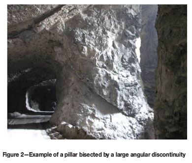
3. Shearing along large angular discontinuities (dip 30° to 70°) resulting in loss of pillar integrity, shown in Figure 2.
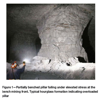
The failed pillars were typically surrounded by pillars that appeared to be stable, showing minimal signs of disturbance. The observations led to the conclusion that the failed pillars represent the low end of the distribution of possible pillar strengths, and not the average pillar strength.
Of particular concern was that the failed pillars were impacted by large angular discontinuities. It was estimated that these pillars failed when the average pillar stress was only about 5% of the uniaxial compressive strength of the limestone rock material. Discontinuities are not always readily visible to production staff when developing a pillar, but become apparent only when the pillar becomes fully loaded or when bench mining is carried out around the pillars. Particularly hazardous conditions can result if large angular discontinuities cause unstable blocks to slide or topple from the pillar ribs. Of the eighteen failed pillars identified in the above studies, seven were associated with large angular discontinuities. It was also observed that widely spaced angular discontinuities were present in the majority of limestone mines. Clearly, the effect of large discontinuities has to be taken into account in the design of pillar systems in limestone mines.
Empirical design approach
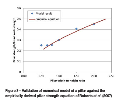
The empirically developed design approach of Roberts et al. (2007) was adopted for estimating the strength of pillars in limestone mines. Using this approach, the strength of a pillar that is square in plan can be expressed as follows:
where w and h are the pillar width and height in metres. The value of k can be expressed in terms of the uniaxial compressive strength (UCS) as follows:

This equation predicts the average or expected strength of a pillar and does not explicitly account for large angular discontinuities. For example, a 15 m wide by 15 m high pillar can be expected to have a strength that is 29.6% of the UCS of the rock material. However, field data shows that such a pillar may fail when the stress is only about 5% of the UCS if it is intersected by a large angular discontinuity. The concern was that a collapse can occur if angular discontinuities weaken a large proportion of the pillars in a panel. Therefore, it was decided to introduce an adjustment to the pillar strength equation that accounts for the weakening effect of angular discontinuities. However, the lack of sufficient field cases made it impossible to conduct a statistical analysis of the failed cases to estimate the impact of the angular discontinuities. Numerical models were therefore used to investigate the likely effect of discontinuities on pillar strength.
Modelling analysis
The numerical models were designed specifically to determine how the inclination and frequency of large, roof-to-floor discontinuities would affect the strength of the slender pillars found in limestone mines. The two-dimensional finite difference software UDEC (Itasca Consulting Group, 2006) was used to model the pillars.
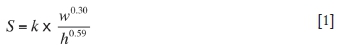
Model calibration and validation was carried out against the empirically developed pillar design method of Roberts et al. (2007) as well as the Lunder and Pakalnis (1997) pillar strength equation for hard rock pillars (Esterhuizen et al., 2008). Models were created to simulate pillars with width-to-height ratios of 0.5 to 2.0 and the results compared to the empirically developed equations. These models did not contain any explicitly modelled angular discontinuities. The rock mass properties were selected to simulate a good quality rock mass representative of the rock found in limestone mines. Figure 3 shows the comparison between empirical and model results. It was concluded that the modelling method provides a realistic representation of pillar strength over the range of width-to-height ratios shown.
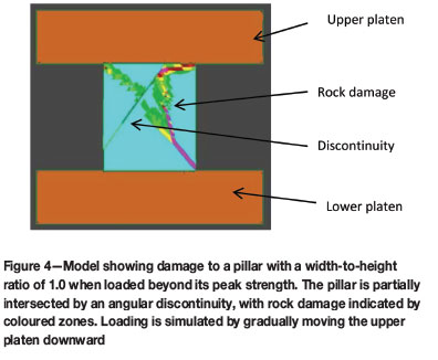
Further modelling was conducted by introducing large angular discontinuities into the pillar models. Various analyses were carried out in which the dip of the discontinuity was varied from 30° to 90° and the strength of the pillar was determined by simulating the gradual compression of the pillar until it reached its peak resistance and started to shed load. Figure 4 shows one of the models, indicating the location of the angular discontinuity and associated rock failure. A series of curves was fitted to the peak resistance of each modelled pillar (Figure 5). The results show firstly that as the discontinuity dip increases from 30° to about 60°, its impact on the pillar strength increases. When the discontinuity dip is greater than 70°, the effect starts to diminish. A vertical joint through the centre of a pillar is seen to have a relatively small impact on pillar strength. These trends in the relationship between pillar strength and discontinuity dip are similar to the results obtained when testing laboratory specimens with inclined planes of weakness.
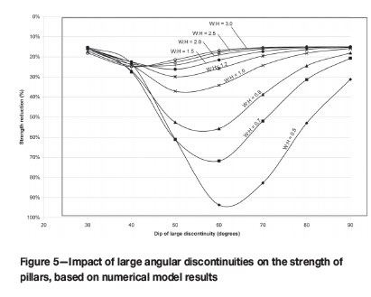
The width-to-height ratio is also shown to be a significant factor affecting the impact of large discontinuities. Figure 5 shows, for example, that a pillar with a width-to-height ratio of 0.5 will suffer a 93% reduction in strength if it is intersected by a 60° dipping joint, while a pillar with a width-to-height ratio of 1.0 would only suffer a 34% reduction in strength. The observation that slender pillars intersected by large angular discontinuities can fail when the average stress is only about 5% of the intact rock strength confirms that these large strength reductions do occur in the field and are similar to those predicted by the numerical models.
Application to design
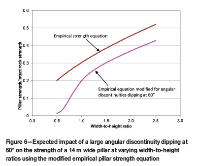
The recommended pillar strength equation for limestone mines in the USA includes a large discontinuity factor (LDF) to account for the impact of large discontinuities on pillar strength (Esterhuizen et al., 2008). The LDF accounts for both the dip angle of discontinuities and the frequency of discontinuities, based on the results shown in Figure 5. Figure 6 shows an application of the modified design equation, in which the impact of a single large discontinuity dipping at 60° on the strength of a 14 m wide pillar is estimated. The discontinuity causes a much greater reduction in pillar strength as the width-to-height ratio drops below 1.0. This case demonstrates how numerical models were used to develop an understanding of the issue of large angular discontinuity impact on pillar strength in the absence of sufficient field cases to conduct a statistical analysis. The outcome of this work was used to explain the unusually low strength of pillars that collapsed in a marble mine in 2010 (Phillipson, 2010).
Case study 2: stress impacts on coal mine entry stability
Effects of horizontal stress on roof stability
Horizontal stress has long been known to be a significant factor contributing to roof instability in bedded rocks in both coal and hard rock mines (Aggson and Curran, 1978; Herget, 1987; Mark and Mucho, 1994; Iannacchione et al., 2003). In coal mines in the USA, horizontal stresses are normally greater than vertical stresses. They can cause compressive-type failures in the bedded roof rocks (Mark and Barczak, 2000) and are a critical factor in the stability of mining excavations. The horizontal stresses are closely related to the global tectonic forces (Mark and Gadde, 2008) in the North American plate. One feature of the horizontal stress field is that the magnitude of the major horizontal stress is about 50% greater than the minor horizontal stress. As a result, excavation performance can be highly dependent on the orientation of the long axis of the entry relative to the major horizontal stress (Mark and Mucho, 1994). This case study has the objective of better quantifying the effect of entry orientation on entry stability.
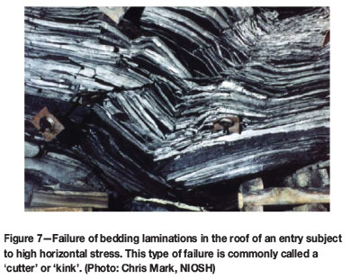
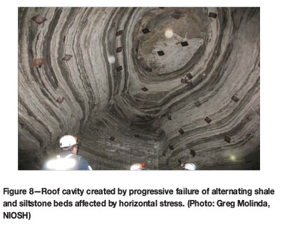
Roof instability of bedded rocks subject to high horizontal stress can take many forms. Failure is often observed to be preceded by 'delamination' of the bedded rock into thin beams in the roof or floor of an excavation (Colwell and Frith, 2010). The thickness of these delaminated beams is determined by the geological composition of the rock, and can vary from tens of centimetres to less than 1 cm. These individual beds are much weaker than the original combined beam and have an important impact on the strength and failure development within the roof. A second commonly observed failure mode is known as 'cutter' or 'kink' failure, in which crushing and local buckling of thinly laminated roof beds occurs near the corners of an excavation. The kink band or cutter is progressive and typically forms a near-vertical zone of failed rock (Hill, 1986). Figure 7 shows an example of cutter or kink failure in thinly laminated strata. The near-vertical zone of crushed rock that results from this failure mode can lead to the progressive collapse of the entire roof, as shown in Figure 8.
The stability of critically stressed excavations can be highly dependent on their orientation relative to the major horizontal stress. Many cases have been reported where the ground conditions in a mine were significantly improved by simply orienting the main development direction near-parallel to the major horizontal stress (Mark and Mucho, 1994).
Empirical design approach
Modern support practices using rock reinforcement have evolved in US coal mines since the 1960s. Extensive historical experience exists with successful and unsuccessful support systems in a wide variety of ground conditions. Based on this experience, NIOSH developed an empirical support design procedure, called 'Analysis of Roof Bolt Systems' (ARBS) (Mark et al., 2001). The procedure is based on a statistical analysis of roof falls and support performance at 37 coal mines across the USA. The ARBS makes use of the Coal Mine Roof Rating (CMRR) (Molinda and Mark, 1996) to quantify the stability of the roof rocks. The support intensity is expressed by an index parameter called PRSUP which combines the bolt length, spacing, capacity and, entry width into a single parameter as follows:

where L is the bolt length in metres, N is the number of bolts per support row, C is the bolt capacity in kilonewton, S is the bolt row spacing in metres and We is the width of the excavation in metres. A discriminant line, which defines the required PRSUP to achieve acceptable entry stability for a given CMRR, was determined by statistical analysis of the case histories of 'acceptable' and 'unacceptable' support performance. The required support intensity is given by:

where H is the depth of cover in metres. The horizontal stress is not explicitly included in the calculation of either the CMRR or the PRSUP, but is indirectly related to the depth of cover. Consequently, the empirical design approach cannot be used to investigate the impact of various orientations of the entry relative to the major horizontal stress.
Modelling analysis of horizontal stress effects
A numerical modelling study was conducted in which calibrated numerical models were used to investigate the impact of horizontal stress on entry stability. The first objective of the study was to develop a modelling method that allows the stability of an excavation to be quantified in meaningful manner. Model outputs can be expressed in terms of degree of deformation or volume of failure, but these outputs are indirectly related to stability. The operating engineer is interested in the degree of stability of the excavation. The concept of a factor of safety, which is widely used and accepted in engineering practice (Harr, 1987), was selected to express the stability of the modelled excavations.
For this modelling study, the strength reduction method (SRM) (Zienkiewicz et al., 1975) was selected to calculate the factor of safety of supported coal mines entries (Esterhuizen, 2012). The SRM was originally developed to provide an alternative method of calculating the stability of rock slopes using numerical models. It has since found acceptance in rock slope design (Lorig and Varona, 2000; Diederichs et al., 2007), but has not been widely used for underground excavation stability analysis. The SRM is uniquely suited to the objective of expressing entry stability in a format that is meaningful to operating engineers.
The SRM safety factor is determined by first conducting a stability analysis of an excavation using average rock strength properties. Depending on the outcome, the analysis is repeated using either a decreased or increased strength until the point of failure is satisfactorily defined. The safety factor of the system is simply calculated as the inverse of the strength adjustment factor at the point of collapse of the modelled excavation. For example, if collapse occurs when the strength is reduced by a factor of 0.8, the safety factor would be 1.25.
The state of 'failure' being investigated must be clearly defined when using the SRM. For this study, an entry is considered to have failed if roof collapse in the model exceeds the bolt length. The term stability factor is used in this paper because the stability is expressed as a ratio of strengths of the rock mass, rather than the ratio of strength to load, as used in the classic safety factor calculation. The interpretation of stability factors is similar to the interpretation of safety factors. A stability factor of 1.0 indicates a system that is at the point of failure, while less than 1.0 indicates an increased likelihood of failure and greater than 1.0 indicates increased likelihood of stability.
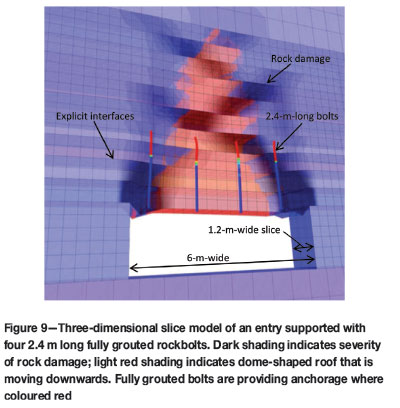
The FLAC3D (Itasca Consulting Group, 2011) finite-difference code was used to conduct the strength reduction analyses. Figure 9 shows one of the models, which simulates a vertical slice through a 6 m wide coal mine entry. The thickness of the slice is equal to the support row spacing, typically 1.2 m. Strata layering is modelled with explicit interfaces between the different lithologies. Rockbolts are modelled using the built-in structural elements available in FLAC3D. The bolts are located along the centre line of the slice. The bedded strata are modelled using the strain-softening ubiquitous joint constitutive model available in FLAC3D. The strength parameters of the rock matrix and the bedding planes are specified separately in the model. It was found that modelling of the anisotropic strength of the bedded rock was a requirement to achieve realistic rock mass response (Esterhuizen and Bajpayee, 2012).
The model inputs and results were initially calibrated against field instrumentation studies. The calibration studies included rock deformation, bolt loads, and entry stability analysis in a variety of geological conditions encountered in the US coal regions. During the calibration stage, a systematic procedure forobtaining model inputs from field data was developed based on the CMRR (Esterhuizen et al., 2013). Using this approach, the rock mass is divided into units, each unit having similar strength properties. The procedures can be used by support designers to create numerical models in the absence of detailed laboratory test results.
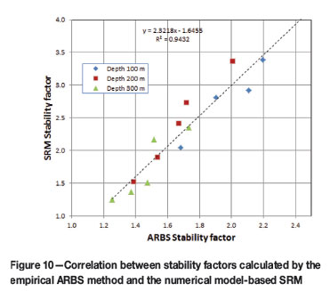
The SRM-calculated stability factors were validated by comparing them to ARBS-calculated stability factors. For this study, a total of 15 different cases were evaluated consisting of entries located at three different depths of overburden with five different roof compositions (Esterhuizen et al., 2013). The support system consisted of five fully grouted rockbolts in a 6 m wide entry. The bolt row spacing was 1.2 m. The stability factors of the 15 cases were first evaluated using the ARBS method. For the SRM analyses, the 15 cases were evaluated for three different stress scenarios. The stress scenarios were selected to represent the range of likely horizontal stress conditions in US coal mines. The SRM results for the three different horizontal stress scenarios were averaged to allow comparison to the ARBS stability factors. This was done because the ARBS stability factor is based on a discriminant line that represents the entry performance under averaged horizontal stress conditions. Figure 10 presents the correlation between the stability factors of the two methods at 100 m, 200 m, and 300 m depth of cover. The excellent correlation between the results of the statistically based ARBS method and the SRM confirms the validity of SRM results.
Horizontal stress effects quantified by numerical models
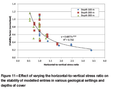
A series of SRM analyses was conducted in which the stability factors of entries in various geological settings and field stress conditions were varied. The entries were located at depths of cover of 100, 200, and 300 m. The ratio of the horizontal to vertical stress in the plane perpendicular to the axis of the entry was used to quantify the horizontal stress effect. This ratio is commonly known as the k-ratio in rock engineering. The resulting stability factors were normalized by the depth in metres, the CMRR, and the strength of the immediate roof layer in MPa. Figure 11 shows the results for a 6 m wide entry supported by four fully-grouted 1.8 m long bolts, with rows 1.2 m apart. There is an inverse relationship between the stability factor and the k-ratio. The relationship can be expressed as follows:

Using this relationship, the change in the stability factor with changes in the k-ratio (k) can be estimated as follows:
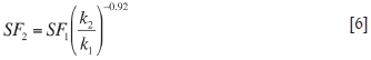
Consider a 6 m wide entry at 200 m depth in the eastern USA in which the major horizontal stress is 2.5 times the vertical stress and the minor horizontal stress is 1.5 times the vertical stress. Assume the stability factor of an entry is estimated to be 1.6 when calculated by the empirical ARBS method. This stability factor is representative of the entry performance under the average stress conditions, which is a k-ratio of 2.0. The stability factor in the 'poor direction', that is, if the major horizontal stress is perpendicular to the axis of the entry (k-ratio is 2.5), can be calculated to be 1.30 using Equation [6]. The stability factor in the 'good direction' (k-ratio is 1.5) is calculated to be 2.08. In this example, the reduced stability factor in the 'poor direction' indicates that action will be required to ensure a stable, safe entry, while entries developed in the 'good direction' can be expected to be adequately supported. The above relationship can be incorporated in empirically based support design equations to better represent the impact of horizontal stresses in the empirical model.
Discussion
The two case studies show how specific stability issues identified during empirical observations can be evaluated using numerical models. In the case of the limestone mine pillars, the impact of large angular discontinuities was identified as a potential safety hazard. However, the lack of sufficient case histories in the field made it impossible to conduct a statistical analysis to quantify their effect on pillar stability. Numerical models were used to investigate a large number of scenarios to develop an understanding of the problem and determine an adjustment to the pillar strength equation that accounts for these structures.
In the second case, empirical observations identified the impact of the k-ratio on excavation stability; however, the empirically developed design method did not explicitly account for horizontal stress. Numerical models were used to investigate the impact of the k-ratio on entry stability and produced a relationship that can be used to quantify the k-ratio effect on stability.
In both cases, the numerical model outputs were validated against empirical observations before detailed analyses of the specific issues were conducted. The numerical model results were then used to extend the usefulness of the empirical models, demonstrating the synergy between the two approaches.
Conclusions
Models of various types are used in rock engineering to determine the likely response of the rock mass around excavations. Empirical models, based on the analysis of large numbers of case histories, have found wide acceptance as a tool for engineering design. The application of empirical models is limited by the restriction that they should not be used beyond the limits of the empirical base from which they were developed. Numerical models are based on the mechanics of rock behaviour and can be used to answer questions about rock mass response under given loading conditions and to extend the empirical models.
Numerical models must be validated against empirical data. The process of first calibrating numerical models against specific case histories is required because of the uncertainty associated with rock mass strength parameters. The validity of the models can then be tested against empirically based models.
Synergy exists between the empirical and numerical modelling approaches. Empirical models can be used to validate numerical models, and numerical models can be used to extend the utility of empirical models.
The two case studies presented show how numerical models were applied to answer questions about specific aspects of excavation stability that existing empirical models were unable to provide.
The combined application of numerical and empirical models can help to improve understanding of causes of stability and instability in excavations, resulting in efficient design and increased safety.
Acknowledgements
The contributions of my colleagues at the NIOSH Office of Mine Safety and Health Research in the research presented here are gratefully acknowledged. The willingness of mine staff to share their experience and allow NIOSH researchers to conduct mine site surveys and measurements have provided the much-needed empirical data for calibration and verification of numerical model results.
Disclaimer
The findings and conclusions in this report are those of the authors and do not necessarily represent the views of the National Institute for Occupational Safety and Health.
References
Aggson, J.R. and Curran, J. 1978. Coal mine ground control problems associated with a high horizontal stress field. AIME Annual Meeting, Denver, CO. 19 pp. [ Links ]
Itasca Consulting Group. 2006. Universal Distinct Element Code (UDEC), User's Guide. Minneapolis MN. [ Links ]
Itasca Consulting Group. 2012. Fast Lagrangian Analysis of Continua in Three Dimensions (FLAC3D), User's Guide. Minneapolis MN. [ Links ]
Barton, N. 2002. Some new Q-value correlations to assist in site characterisation and tunnel design. International Journal of Rock Mechanics and Mining Sciences, vol. 39, no. 2. pp. 185-216. [ Links ]
Bieniawski, Z.T. 1968. In situ strength and deformation characteristics of coal. Engineering Geology, vol. 2, no. 5. pp. 325-340. [ Links ]
Bieniawski, Z.T. and Van Tonder, C.P.G. 1969. A photoelastic-model study of stress distribution and rock fracture around mining excavations. Experimental Mechanics, vol. 9, no. 2. pp.75-81. [ Links ]
Cho, N., Martin, C.D., and Sego, D.C. 2007. A clumped particle model for rock. International Journal of Rock Mechanics and Mining Sciences, vol. 44, no. 7. pp. 997-1010. [ Links ]
Colwell, M. and Frith, R. 2010. AMCMRR-an analytical model for coal mine roof reinforcement. Coal Operators' Conference, University of Wollongong, Wollongong, Australia. p. 302. [ Links ]
Cundall, P.A., Pierce, M.E., and Mas Ivars, D. 2008. Quantifying the size effect of rock mass strength. Proceedings of the 1st Southern Hemisphere International Rock Mechanics Symposium, Perth, Western Australia, September 2008. Australian Centre for Geomechanics, Nedlands, Western Australia. vol. 2, pp. 3-15. [ Links ]
Curran, J.H. and Hammah, R.E. 2006. Keynote Lecture: Seven Lessons of Geomechanics Software Development. Proceedings of the 41st US Symposium on Rock Mechanics: 50 Years of Rock Mechanics -Landmarks and Future Challenges, Golden, Colorado, 17-21 June 2006. American Rock Mechanics Association, Alexandria, VA. 15 pp. [ Links ]
Dershowitz, W.S., La Pointe, P.R., and Doe, T.W. 2004. Advances in discrete fracture network modeling. Proceedings of the US EPA/NGWA Fractured Rock Conference: State of the Science and Measuring Success in Remediation, Portland, Maine, 13-15 September 2004. pp. 882-894. [ Links ]
Diederichs, M.S., Lato, M., Hammah, R., and Quinn, P. 2007. Shear strength reduction approach for slope stability analyses. Proceedings of the 1st Canada-US Rock Mechanics Symposium, Vancouver, BC, 27-31 May 2007. Eberhardt, E., Stead, D., and Morrison, T. (eds.). Taylor and Francis. pp. 319-327. [ Links ]
Elmo, D. and Stead, D. 2010. An integrated numerical modelling-discrete fracture network approach applied to the characterisation of rock mass strength of naturally fractured pillars. Rock Mechanics and Rock Engineering, vol. 43, no. 1. pp. 3-19. [ Links ]
Esterhuizen, G.S., Dolinar, D.R., and Ellenberger, J.L. 2008. Pillar Strength and Design Methodology for Stone Mines. Proceedings of the 27th International Conference on Ground Control in Mining, West Virginia University, Morgantown WV, 2008, pp 241-253. [ Links ]
Esterhuizen, G.S. 2006. Evaluation of the strength of slender pillars. Transactions of the Society for Mining Exploration and Geology. vol. 320. pp. 69-76. [ Links ]
Esterhuizen, G.S. 2012. A Stability factor for Supported Mine Entries Based on Numerical Model Analysis. Proceedings of the 31st International Conference on Ground Control in Mining, West Virginia University, Morgantown, WV, 29-31 July 2014. 9 pp. [ Links ]
Esterhuizen, G.S. and Bajpayee, T.S. 2012. Horizontal stress related failure in bedded mine roofs-insight from field observations and numerical models. Proceedings of the 46th US Rock Mechanics/Geomechanics Symposium. Chicago, IL, 24-27 June 2012. Bobet, A. (ed.). American Rock Mechanics Association, Alexandria, VA. Paper no. 137. 10 pp. [ Links ]
Esterhuizen, G.S., Bajpayee, T.S., Ellenberger, J.L., and Murphy, M.M. 2013. Practical estimation of rock properties for modeling bedded coal mine strata using the Coal Mine Roof Rating. Proceedings of the 47th US Rock Mechanics/Geomechanics Symposium, San Francisco, CA, 23-26 June 2013. American Rock Mechanics Association, Alexandria, VA. Paper 13-154. 14 pp. [ Links ]
Frigg, R. and Hartmann, S. 2006. Models in Science. The Stanford Encyclopedia of Philosophy. http://stanford.library.usyd.edu.au/archives/spr2009/entries/models-science/ [Accessed November 2013]. [ Links ]
Hammah, R.E. and Curran, J.H. 2009. It is better to be approximately right than precisely wrong: why simple models work in mining geomechanics. International Workshop on Numerical Modelingfor Underground Excavation Design. Department of Health and Human Services, National Institute for Occupational Safety and Health, Information Circular IC 9512. pp 55-61. [ Links ]
Harr, M.E. 1987. Reliability Based Design in Civil Engineering. Mc Graw Hill, New York. [ Links ]
Herget, G. 1987. Stress assumptions for underground excavations in the Canadian Shield. International Journal of Rock Mechanics and Mining Sciences and Geomechanics Abstracts, vol. 24, no. 1. pp. 95-97. [ Links ]
Heuze, F.E. 1980. Scale effects in the determination of rock mass strength and deformability. Rock Mechanics, vol. 12, no. 3-4. pp. 167-192. [ Links ]
Hill, J.L. 1986. Cutter roof failure: An overview of the causes and methods for control. US Bureau of Mines, Information Circular IC 9094. United States Department of the Interior. 27 pp. [ Links ]
Hoek, E. and Brown, E.T. 1980. Underground Excavations in Rock. Institute of Mining and Metallurgy, London. 527 pp. [ Links ]
Hucke, A., Studeny, A., Ruppel, U., and Witthaus, H. 2006. Advanced prediction methods for roadway behaviour by combining numerical simulation, physical modelling and in-situ monitoring. Proceedings of the 25th International Conference on Ground Control in Mining, West Virginia University, Morgantown, WV. p. 213. [ Links ]
Hudson, J.A., Brown, E.T., and Rummel, F. 1972. The controlled failure of rock discs and rings loaded in diametral compression. International Journal of Rock Mechanics and Mining Sciences and Geomechanics Abstracts, vol. 9, no. 2. pp. 241-244. [ Links ]
Iannacchione, A.T., Marshall, T.E., Burke, L., Melville, R., and Litsenberger, J. 2003. Safer mine layouts for underground stone mines subjected to excessive levels of horizontal stress. Mining Engineering, vol. 55, no. 4. pp. 25-31. [ Links ]
Kvapil, R. 1992. Sublevel caving. SME Mining Engineering Handbook. Society for Mining, Metallurgy and Exploration, Littleton, CO. pp. 1789-1814. [ Links ]
Laubscher, D.H. 2001. Cave mining - state of the art. Underground Mining Methods: Engineering Fundamentals and International Case Studies. Hustrulid, W.A. and Bullock, R.L. (eds.). Society for Mining, Metallurgy and Exploration, Littleton, CO. pp. 455-464. [ Links ]
Lorig, L. and Varona, P. 2000. Practical slope stability analysis using finite-difference codes. Slope Stability in Surface Mining. Hustrulid, W.A., McCarter, M.K., and Van Zyl D.J.A. (eds.). Society for Mining, Metallurgy and Exploration, Littleton, CO. pp. 115-124. [ Links ]
Lunder, P.J. 1994. Hard rock pillar strength estimation an applied approach. MS thesis, University of British Columbia, Vancouver, BC. [ Links ]
Lunder, P.J. and Pakalnis, R. 1997. Determining the strength of hard rock mine pillars. Bulletin of the Canadian Institute of Mining and Metallurgy, vol. 90. pp. 51-55. [ Links ]
Mark, C. 1992. Analysis of longwall pillar stability (ALPS): an update. Proceedings of the Workshop on Coal Pillar Mechanics and Design. Pittsburgh, PA. US Department of the Interior, Bureau of Mines, Information Circular IC 9315. pp. 238-249. [ Links ]
Mark, C. and Chase, F.E. 1997. Analysis of retreat mining pillar stability (ARMPS). Proceedings - New Technology for Ground Control in Retreat Mining, Pittsburgh, PA. US Department of Health and Human Services, Public Health Service, Centers for Disease Control and Prevention. National Institute for Occupational Safety and Health, DHHS (NIOSH) Publication No. 97-122. pp. 17-34. [ Links ]
Mark, C. and Gadde, M. 2008. Global trends in coal mine horizontal stress measurements. Proceedings of the 27th International Conference on Ground Control in Mining, West Virginia University, Morgantown, WV, 29-31 July 2008. pp. 319-331. [ Links ]
Mark, C. and Barczak, T.M. 2000. Fundamentals of coal mine roof support. New Technology for Coal Mine Roof Support. Proceedings of the NIOSH Open Industry Briefing. NIOSH IC, 9453. National Institute for Occupational Safety and Health. pp. 23-42. [ Links ]
Mark, C. 1999. Empirical methods for coal pillar design. Proceedings of the 2nd International Workshop on Coal Pillar Mechanics and Design. National Institute for Occupational Safety and Health, Report IC 9448. pp. 145-54. [ Links ]
Mark, C. and Mucho, T.P. 1994. Longwall Mine Design for Control of Horizontal Stress. New Technology for Longwall Ground Control. Special Publication 01-94. US Bureau of Mines. pp. 53-76. [ Links ]
Mark, C., Molinda, G.M., and Dolinar, D.R. 2001. Analysis of roof bolt systems. Proceedings of the 20th International Conference on Ground Control in Mining, West Virginia University, Morgantown, WV, 7-9 August 2001. pp. 218-225. [ Links ]
Mathews, K.E., Hoek, E., Wyllie, D.C., and Stewart, S. 1981. Prediction of stable excavation spans for mining at depths below 1000 m in hard rock. CANMET DSS Serial No: 0sQ80-00081. Ottawa. [ Links ]
Martin, C.D. and Maybee, W.G. 2000. The strength of hard rock pillars. International Journal of Rock Mechanics and Mining Sciences, vol. 37. pp.1239-1246. [ Links ]
Mas Ivars, D., Deisman, N., Pierce, M., and Fairhurst, C. 2007. The synthetic rock mass approach - a step forward in the characterization of jointed rock masses. Proceedings of the 11th Congress of the International Society for Rock Mechanics. Taylor and Francis, Leiden. vol. 1, pp. 485-490. [ Links ]
Molinda, G.M. and Mark, C. 1996. Rating the Strength of Coal Mine Roof Rocks. Information Circular IC 9444. US Department of the Interior, Bureau of Mines, Pittsburgh. 36 pp. [ Links ]
Phillipson, S.E. 2012. Massive pillar collapse: a room-and-pillar marble mine case study. Proceedings of the 31st International Conference on Ground Control in Mining, West Virginia University, Morgantown, WV. 9 pp. [ Links ]
Potyondy, D.O. and Cundall, P.A. 2004. A bonded-particle model for rock. International Journal of Rock Mechanics and Mining Sciences, vol. 41, no. 8. pp. 1329-1364. [ Links ]
Power, G.R. 2004. Modelling granular flow in caving mines: large scale physical modelling and full scale experiments. PhD thesis, University of Queensland, Brisbane, Australia. 250 pp. [ Links ]
Roberts, D.P. and Van der Merwe, J.N. 1994. A strain soffening model for coal via back analysis of in situ coal pillar tests. Proceedings of the 11th International Conference on Computer Methods and Advances in Geomechanics. pp. 437-480. [ Links ]
Roberts, D., Tolfree, D., and McIntyre, H. 2007. Using confinement as a means to estimate pillar strength in a room and pillar mine. Proceedings of the 1st Canada-US Rock Mechanics Symposium. Taylor and Francis. pp.1455-1461. [ Links ]
Salamon, M.D.G. and Munro, A.H. 1967. A study of the strength of coal pillars. Journal of the South African Institute of Mining and Metallurgy, vol. 68. pp. 55-67. [ Links ]
Starfield, A.M. and Cundall, P.A. 1988. Towards a methodology for rock mechanics modelling. International Journal of Rock Mechanics and Mining Sciences and Geomechanics Abstracts, vol. 25, no. 3. pp. 99-106. [ Links ]
Thacker, B.H., Doebling, S.W., Hemez, F.M., Anderson, M.C., Pepin, J.E., and Rodriguez, E.A. 2004. Concepts of Model Verification and Validation. Los Alamos National Laboratory, Los Alamos, NM. 27 pp. [ Links ]
Trucanoa, T.G., Swilera, L.P., Igusab, T., Oberkampfc, W.L., and Pilchc, M. 2006. Calibration, validation, and sensitivity analysis: what's what. Journal of Reliability Engineering and System Safety, vol. 91. pp. 1331-1357. [ Links ]
Yeates, R.A., Enever, J.R., and Hebblewhite, B.K. 1983. Investigations prior to the introduction of longwall mining. Proceedings of the 5th International Society for Rock Mechanics Congress, Melbourne, Australia. pp. E71-E77. [ Links ]
Zienkiewicz, O.C., Humpheson, C., and Lewis, R.W. 1975. Associated and non-associated visco-plasticity and plasticity in soil mechanics. Geotechnique, vol. 25. pp. 617-689. [ Links ]
This paper was first presented at the, 6th Southern African Rock Engineering Symposium SARES 2014, 12–14 May 2014, Misty Hills Country Hotel and Conference Centre, Cradle of Humankind, Muldersdrift.

