


Services on Demand
Article
 English (pdf)
 Article in xml format
 Article references
Indicators

Related links
-
 Cited by Google
 -
 Similars in Google
Share

 Permalink
Journal of the Southern African Institute of Mining and Metallurgy
On-line version ISSN 2411-9717
Print version ISSN 2225-6253
J. S. Afr. Inst. Min. Metall. vol.114 n.7 Johannesburg Jul. 2014
PHYSICAL BENEFICIATION
Operation and performance of the Sishen jig plant
H.A. MyburghI; A. Nortje†II
IKumba Iron Ore, Centurion Gate, Centurion, South Africa
II†Kumba Iron Ore, Sishen Iron Ore Mine, South Africa
SYNOPSIS
Sishen Iron Ore Mine previously used only A-grade material (>60% Fe in situ value) from the pit for beneficiating in the DMS plant to a final product grade of 66% Fe in lump and 65% Fe fine ore. The B-grade (between 50% and 60% Fe) and C-grade material (between 35% and 50% Fe) were stockpiled separately, owing to the inability of the existing DMS plant to beneficiate material at densities higher than 3600 kg/m3. The ability to beneficiate the B-grade material at densities higher than 3600 kg/m3 was evaluated, and air-pulsed jigs were found to be techno-economically feasible and value maximizing.
The beneficiation of B-grade material would add to the existing DMS production of 28 Mt/a, with no additional mining cost and only limited costs for the handling of waste and B-material. The objective of the Sishen Expansion Project (SEP), i.e. the jig plant, was to produce 10 Mt/a of saleable product with six modules to the set physical and chemical specifications by 2009. During the start of construction, it was decided to add another two jig modules to the plant to increase production to 13 Mt/a.
During commissioning and ramp-up the shortcomings and advantages of the jigs were fully experienced and understood, resulting in many changes to optimize jigging performance.
Keywords: jigging, jig efficiency, jig control, physical separation, process optimization.
Introduction
Kumba Iron Ore's Sishen mine in South Africa produces 41 Mt of iron ore per annum from its beneficiation plants. The orebody consists mainly of laminated and massive haematite ore, of which 34 M/a is crushed to -90 mm before beneficiation by means of a combination of Wemco drums and dense medium cyclones. In addition, 22 Mt/a is crushed to -25 mm for beneficiation in the jig plant, which consists of eight modules of three jigs per module. The feed to each module is screened into three fractions that feed three different jigs. The Coarse Jig receives -25 mm +8 mm material, the Medium Jig is fed with -8 mm +3 mm material, and the Fine Jig receives -3 mm +1 mm material.
The jig plant with its 24 jigs was in full production towards the end of 2009, providing an equivalent of 10 Mt product per annum and above 13 Mt in the following two years. The jig plant was designed to receive lower grade material that needs a cut density of 4100 kg/m3 and higher to be able to produce the product to the specification at a design yield of 57.8% from an average Fe feed grade of 56%.
During hot commissioning and for two years after commissioning, many challenges were encountered and rectified, resulting in improved jig plant performance.
Plant layout
The feed material to the jig plant at Sishen Iron Ore Mine is reduced to a -25 mm top size in a three-stage crushing circuit and longitudinally stacked on two pre-beneficiation feed beds (Figure 1). The pre-beneficiation feed bed material is reclaimed by a drum reclaimer and conveyed to eight feed bunkers. Each of the eight conveyers feeds one jig module and belt scales on each conveyer control the feed rate.
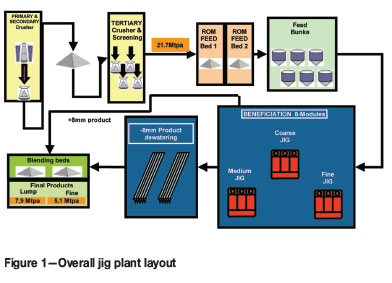
The jig plant consists of eight modules with three jigs each: the Coarse Jig (-25 mm +8 mm), Medium Jig (-8 mm +3 mm), and Fine Jig (-3 mm +1 mm). The feed to the plant is spread evenly over the width of the primary double-deck screen with a shuttle conveyer. The top deck overflow feeds the Coarse Jig. The overflow of the bottom deck of the primary screen flows to a shuttle conveyer that spread the material evenly over the width of the chute that feeds the Medium Jig. The underflow of the primary deck flows to a single-deck secondary screen where the -1 mm material is screened out before the oversize material flows into the Fine Jig. The waste from all the jigs is conveyed on one conveyer system to the waste dump.
After beneficiation, the lumpy ore product (-25 mm +8 mm) is conveyed and stacked on the product blending beds, while the fine material (-8 mm +1 mm) is conveyed to the dewatering bunkers, where it remains for about four hours before being stacked on the fine product blending eds.
Jig construction and control
The jigs at Sishen Iron Ore Mine are under-bed pulsating jigs that are fully PLC-controlled. All the jigs are 3 m long, and the width varies from 4 m for the Coarse Jig to 3.5 m for the Medium and 2.2 m for the Fine Jig. The different widths for the jigs were selected to cater for the expected product size distribution (PSD) from the crusher circuit, taking in account the required specification for the final product.
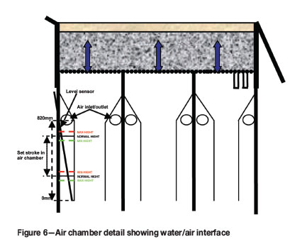
The jig has a screen deck to support the jig bed and allow the water pulse generated in the air chambers to lift the beds to an acceptable height for the specific material and the hutch water. The hutch water flows through the bed at a constant rate to assist with the separation efficiency and keep the bed fluidized for longer. At the end of the jig, a float measures the stroke of the bed and indicates the product bed height. The height of the product bed is an indication to the PLC to open or close the product gates in small increments to control the product bed height in a narrow band around the set value. The waste flows over the weir at the end of the jig while the product is collected in the hopper underneath the jig. High-and low-level probes start and stop the feeder to control the extraction of the product (Figures 2 and 3).
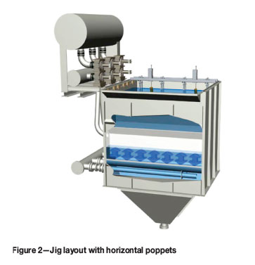
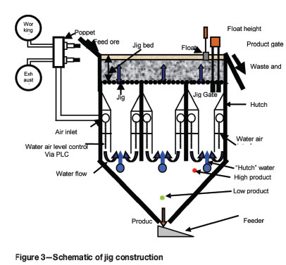
The pulse is created by air that enters and exits the air chambers situated underneath the screen deck. The air forces the water in the air chamber down, creating the pulse on the ore bed, and lets the air out to allow the ore bed to settle on the jig screen deck before the next pulse begins. The air is generated by a blower and stored in the working air vessel. Poppet valves control the air that enters and exits the air chambers. The air/water interface level in the air chambers is measured by level probes, which control the poppet valve timing to keep the stroke in the air chamber constant.
Plant ramp-up
The throughput of the jig plant, as in most plants, is based on three primary drivers: run hours, feed tempo, and yield. In order to achieve the plant's nameplate capacity of 13 Mt/a, each of these had to be addressed and understood as each affects the others. The plant ramp-up was planned over a period of one year after the last module was hot-commissioned, although reaching full capacity took three years due to a number of reasons. However, the yield expectation changed significantly, along with a change in feed and product quality, in the years that followed.
The initial ramp-up was aimed at understanding the basics of jigging control parameters and their effect on feed tempo and yield. During this period a lot of focus was placed on jig control to achieve the specified qualities of 64% Fe lump and 63.5% Fe fine product at the highest yield possible. It was soon realized that running a jig plant is not only a matter of correctly controlling the jig, but that each of the drivers would have to be addressed in order achieve nameplate capacity at the correct product quality.
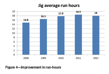
After the basics and the control of the jig were understood, a lot of focus was placed on uptime/runtime as this is the basis for throughput. The major issues were components continually failing, control instruments not being fit for purpose, and long times required to repair and/or replace components. It also became apparent quite early that the wear of the jig components was much higher than expected, which also caused the loss of run-hours.
Through good understanding of the process and good collaboration between metallurgy, maintenance, and operations, various innovative in-house solutions were created. The same approach was followed for finding external solutions, in which the suppliers played an active part. This ensured a steady ramp-up in run-hours, as shown in Figure 4, and made a large contribution to the overall ramp-up in throughput. It should be noted that the 2012 run-hours were lower than 2011 due to the lack of feed available from mining as well as a planned hutch replacement, which took out three modules for a whole week at a time.
The correct feed tempo to the jig is important in order to achieve sufficient stratification. The impact of higher tempos needs to be understood as it influences the retention time of particles in the jig, allowing less stratification time.
The yield (mass recovery) is the single most important driver and also the most difficult to understand as there are many factors that affect quality, which in turn affects yield. A lot of dedicated effort was put into understanding these factors. They include feed quality and blend, mechanical condition of the jig components, as well as metallurgical issues affecting the separation efficiency, e.g. bed lift, near-density material, etc. However, understanding is only a part of the solution and effort went into collaborating with the mining as well as plant maintenance and operations teams to improve the overall yield.
The effect of this can be seen in the actual yield figures as shown in Figure 5:
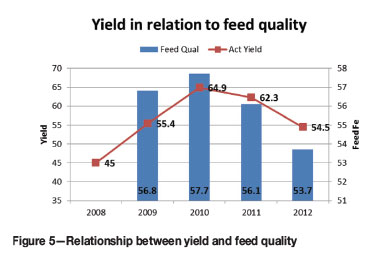
► The 2008 yield, at 45.0%, was low as the plant was newly commissioned and little was known about the control philosophy of jigging that influence separation efficiency, with a consequent negative effect on the yield
► The 2009 yield, at 55.4%, was a major improvement, brought about through the increased understanding of the jig control parameters. A lot of focus was also placed on feed quality and plant metallurgical acceptability
► The 2010 yield, at 64.9%, was a further big improvement on the previous year's yield. This was the direct result of a metallurgical focus on the jig as well as high-grading (adding more A-grade material) in order to achieve the target chemical qualities at yield. There was also a shift in mining focus from considering not just feed quality but also beneficiation qualities
► The 2011 yield, at 62.3%, was a great achievement on the back of much lower feed qualities (1.6% Fe less than in 2010). The focus was on optimizing the use of A-grade material, which meant that less A-grade material was sent to the jig plant. However, the chief contribution to the good yield was the production of lower quality products (63.2% Fe lump and 62.2% Fe fines) in the second half of 2011
► The 2012 yield, at 58.6%, dropped significantly on the back of even lower feed qualities than the previous year (1.9% Fe less compared to 2011). However, the yield was very good considering the feed quality. Increasing focus was being placed on better efficiencies through improved monitoring and understanding through quantification, as well as improving separation efficiency factors. Predictions on product yield improved significantly, approaching the original estimated grade and yield relationship.
The most important learning outcome during the first three years of the plant was an understanding of the basic factors that affect jig separation efficiency. If these factors had been known and understood during ramp-up, nameplate capacity would have been reached sooner.
Factors affecting jig separation efficiency
Basic factors of jigging
Jigs have been used in mineral beneficiation for more than 100 years, mainly because of their simplicity and low cost.
The principle of operation is that the terminal velocity of a particle falling through water is determined by the drag of the water on the particle, creating an upward force, and the downward force of gravity. The drag is a very strong function of the surface area, which is in turn determined by two factors, namely the size of the particle and its shape. Terminal velocity is thus a function of three factors - particle size, shape, and density. A spherical particle has a higher terminal velocity because it experiences less drag than a flat particle with the same mass. Similarly, a lighter particle will have a smaller terminal velocity than a heavier particle of the same shape and size. Finally, small particles will have a lower terminal velocity than large particles of the same density and shape.
Separation in a jig takes place in a bed of particles about 250 to 500 mm thick, suspended on a screen deck and fully submerged in water. The aperture size of the screen is smaller than the smallest particle. A water pulse is applied for a fraction of a second from underneath the screen through the bed of particles, at a velocity higher than the maximum terminal velocity of the particles. A continuous stream of hutch water with a continuous positive upwards flow improves the separation during the settling phase of the bed. All the particles are thus forced upwards, but those with a higher drag and lower mass will be displaced to a higher level under the upward water pulse. This upward force is then removed and the particles are allowed to settle. With continual repetition of the cycle, the low-drag high-density particles migrate to near the screen deck while the high-drag low-density particles migrate to the top of the bed. The product is removed through the product gate at the end of the screen and the lighter particles on top of the jig bed flow over the discard weir.
To summarize, the high-density particles, the large particles, and those with a spherical shape collect at the bottom of the bed, while the low-density particles, the small ones, and the flaky particles end up on top. This also exposes the weakness of the jig. The separation will be poor if the desired product is flaky and the discard more equidimensional and/or has a small density difference. The same applies if particles of all densities occur in the feed, in which case a layer is formed that contains particles of intermediate density, size, and shape, called the middling or near-density fraction. If there are too many near-density particles, the product layer tends to be thin, resulting in poor separation. A jig performs the best where proper liberation of the ore has taken place and where large differences in density occur, as in the case of metal separation from slag or coal from shale.
External factors that affect the separation efficiency of the jig
The external factors that have the biggest influence on jig efficiency are:
► Feed rate (retention time in jig)
► Chemical composition of feed material
► Percentage of near-density material in the feed
► Particle size and mass distribution into the jig
► Screen efficiency
► Particle size distribution (PSD) of feed material.
Pre-beneficiation beds were included before the beneficiation process to homogenize the feed to the jig plant, due to the following reasons:
► The varying chemical composition in the feed from the mine, which can also result in a varying percentage of near-density particles, depending on the type of ore mixture available in the pit at that time
► The varying PSD in the ROM feed, which will affect the split between the three jigs in a module, thus the feed rate (retention time)
► The ability to set up the jig operational parameters optionally for each jig, thereby optimizing product grade-yield interdependency
► Less selective mining affects the feed to the jig plant, as is also the case with feeding the DMS plant.
Because of the size of the open pit (12 km χ 2.5 km), the feed to the plant is trucked from different loading points in the mine with ore types that differ mineralogically, resulting in variation in the chemical composition of the feed. Different kinds of ore also have different crushing characteristics, thus resulting in a variable PSD in the ROM feed.
Varying chemical compositions and amounts of near-density material in the feed to a jig would require continuous changing of the jig settings for optimum beneficiation efficiency. Since laboratory analysis is undertaken on composite product samples taken at two-hourly intervals, it would be difficult to maintain the optimum efficiency in the plant and some product would be misplaced due to the requirements of maintaining a constant chemical specification on the products beds.
Owing to the PSD variation in the feed, the feed rate to the different jigs varies continuously, with the possibility of exceeding the maximum feed rate to a certain jig and thus lowering the beneficiation efficiency of that specific jig.
With the pre-beneficiation bed capacity varying from a minimum of 80 000 t to 160 000 t per bed, the plant can run for two days or more with minimum changes to the jig settings, with slight adjustments to maintain chemical specification on the product beds, depending on the product bed chemical composition. This makes it possible to extract the optimum yield and product grade from the feed material if the pulse characteristics are optimized and maintained for each feed bed.
The shuttle conveyers used in the plant ensure that feed material at a constant PSD is evenly introduced into the jigs. Uneven distribution of feed over the width of the jig results in uneven stratification of particles and a large variance in particle retention time in the jig, causing extensive product and discard misplacement. It is also important that the PSD spread over the jig width is homogeneous to maximize the effectiveness of the separation process.
The negative impact of the percentage near-density material in the feed can be controlled to a certain degree by reducing the feed rate and/or increasing the weight on the floats. By increasing the weights the cut density is increased and more near-density material is removed to waste, decreasing the thickness of near-density particle layer underneath the float and thus reducing the misplacement of waste in product. The effect of varying feed chemical composition will have an effect on the product quality, and can be controlled by increasing or decreasing the height of the product bed that forms underneath the float, forcing more or less near-density particles to the product.
During the study phase of the jig plant project, different types of material were treated in a side-pulse test jig (3 m length x 0.620 m width). After the coarse fraction (-25 mm +8 mm) was successfully tested, the fine fraction (-8 mm +1 mm) was treated. After a few tests on the fine fraction the material was split into two fractions (-8 mm +3 mm and -3 mm +1 mm). Beneficiating the two fractions separately resulted in a 12% improvement in product yield compared to beneficiating the single fraction (-8 mm +1 mm). This is due to the fact that the finer -2 mm material is lost to the waste because of its particle size and the control parameters needed to successfully separate the top size 8 mm particles in the jig bed. This also indicated that the screening of the feed into the three size fractions to the different jigs must be within acceptable tolerances, otherwise the misplaced fine material to the wrong jig will result in the loss of product to waste.
Internal factors that affect the separation efficiency of the jig
The efficiency of the stratification of iron ore in jigs depends mainly on correct pulse characteristics, i.e. jig pulse shape, amplitude, and frequency. The mechanical condition of the various components used to create the pulse also has a direct influence. It is most important that the whole bed lifts up simultaneously, and no 'dead' areas must be present on the screen deck. No bed lift will occur in dead areas, thus no separation will take place and the forward movement of the rest of the ore bed will cause a downwards suction effect that will draw the waste in this area down to the bottom layer, undoing the stratification effort of the jig bed. After the material moves out of the dead area into the live area, separation will start again. If the dead area is near the product gate the mixed bottom layers will be drawn into the gate and a lower quality product will be obtained. The height of the lift should be at least three times the top size for coarse particles (> 75 mm lift for -25 mm +8 mm ore) and up to six times the top size for fine particles (> 18 mm lift for -3 mm +1 mm ore).
Provided that the pulse characteristics are correct, the beneficiation efficiency will be maximized. Some of the internal factors that can affect the separation efficiency by affecting/changing the pulse characteristics are:
► Blocking of the punch plate at gate and screen deck Any dead area in a jig bed, as described, will have an effect on separation efficiency. These problems were rectified where possible
► Weight of floats. The weight of floats can vary by up to 500 g and needs to be calibrated. Weights added on the floats for bed chemical quality control should be only 100 g at a time, and float weights that differ by more than 50 g will make product chemical quality control difficult
► Poppets
- Poppet timing (travel speed)
- Poppet travel distance.
Any defect affecting the speed of the poppet and travel distance will affect the pulse control and thus the separation efficiency.
► Poppet arrangement-The first poppets were functioning horizontally, increasing the wear on the moving parts. The poppets were changed so that they functioned vertically, increasing the life of the moving parts from a few months to a few years
► Accurate calibration of all instruments is essential for consistent product quality and yield optimization on 24 jigs
► Wave breakers inside air chambers-With jigs up to 4 m wide, it is difficult to control the water-air interface in the air chambers and waves start to form, affecting the pulse and lift on the bed, which in turn adversely affect the separation efficiency. Wave breakers were installed in the air chambers to overcome this problem
► Rubber seals on jig product gates-Rubbers were installed on the gates of the fine and medium jigs to ensure that the product does not leak through continuously, thus improving control on the product bed and the extraction of product from the jig
► Air chambers level sensors-Changing the reading speed from 200 ms to 100 ms helped with the control of the bed lift. A faster sensor could improve the control even further.
If all the above-mentioned factors are 100% correct but the product gate design is wrong, a low-quality product will result. The product gate must be designed in such a way that the ore bed in the jig above the gate is still alive (moving upwards with the pulse) and will lift to the desired height, depending on the top size. The extraction of product via the product gate must be controlled in such a way that the height of the product bed (underneath the float) in the jig will stay within a narrow margin. If the product bed drops too low, the possibility of extracting waste and undesired near-density material increases, resulting in reduced product quality and product yield through compensating for quality.
Pulse timing and travel distance
A pulse cycle starts when the working air poppet receives a signal to open and allows air to enter the air chambers. The air will push the water/air interface in the air chamber downwards, carrying the energy over to the ore bed and lifting the jig bed with the desired stroke upwards. The cycle ends after the water/air interface in the air chamber has moved back to its original position, implying that the ore bed has settled back to its original position. This is just before the air enters the air chamber to start the next cycle.
Two poppets per chamber control the inlet and outlet of the air in the air chambers and the timing is controlled by a PLC. During the pulse cycle the working air poppet must open and close before the exhaust poppet opens and closes. The time to open and the distance the poppet must travel are thus important for controlling the pulse and lift (stroke) on the bed in order that proper segregation takes place.
The pulse frequency of the jigs is currently set at:
► Coarse Jig - 60 pulses per minute
► Medium Jig - 70 pulses per minute
► Fine Jig - 90 pulses per minute.
The time for each pulse cycle to be completed is as follow:
► Coarse Jig - 1000 ms
► Medium Jig - 857 ms
► Fine Jig - 667 ms.
The Fine Jig poppets have the shortest cycle period. The poppet construction and functioning for all three jigs, is the same, therefore it can be assumed that if the poppet travel speed and distance is correct for the fine, medium, and coarse jigs, then the control of the pulse forming and the lift (stroke) of the ore bed will be optimized.
The distance set for the poppets to travel for all the jigs is 55 mm and can be readjusted, if necessary. By keeping this value constant for all the jigs the rest of the settings can then be adjusted for optimum pulse control, keeping in mind that the thickness of the poppet rubbers sealing the working air from the jig's air chambers will start to decrease, increasing the poppet travel distance.
Figure 7 illustrates the poppet timing (black dotted line) and the reaction of the water/air interface (blue line) in the air chambers. It takes a new poppet 75 ms to travel the 55 mm set distance. At time TT1W the working air receives a signal to open and will be fully opened at time Tt2W, well before the order to close reaches the poppet at time Tt3W. At time Tt4W the poppet is closed. At this stage the water/air interface reaches the set value after time TP2 in the air chamber and the bed reaches the maximum lift required for optimum separation. The ore bed movement will differ from the blue graph, especially at the beginning of the pulse, because of the inertia of the ore bed at the beginning of the cycle. After the working air poppet has closed and before the exhaust poppet opens at time TT1E the bed will be in suspension and will start to settle. During this period separation takes place as the heavier ore particles settle faster than the lighter waste particle.
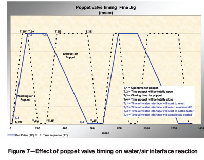
At time TT1E the exhaust poppet will receive the signal to open. It will be fully opened at time TT2E, well in advance of the signal to close at time TT3E, and it will be fully closed at time Tt4E. During this period the water/air interface in the air chamber will move back to its original set position, forced only by the water in the jig and the ore on the jig screen. After a few milliseconds the cycle will start again to create the next pulse.
Times Tt1W and Tt1E are fixed time settings and can be changed only on the PLC. Times TT3W and TT3E have three values, a normal, maximum, and minimum value. In the air chamber a certain stroke is needed to obtain the correct stroke on the ore bed in the jig. If the water/air interface has drifted off the normal of the two set values (height values) in the air chamber to either the maximum or minimum side, the PLC will advance or retard the poppet's timing by a few milliseconds to try and keep the two set values at the normal set value and thus maintain the stroke in the air chamber and the pulse characteristic on the ore bed in the jig.
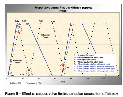
Any mechanical defect in the poppets affecting the time/speed of the poppet that cannot be rectified by the PLC will have a negative effect on the pulse characteristics and will affect the jig separation efficiency (Figure 8).
Conclusion
Attaining the ramp-up targets of the Sishen jig plant as planned was no mean feat, and was achieved through a collaborative effort between metallurgy, maintenance, operations, and suppliers, and by not accepting any performance as the norm but adopting an approach of continuous improvement and teamwork. The product target of 13 Mt/a was achieved, assisted by a higher yield than planned and by the increase in working knowledge obtained during this period.
The most important basic factors to take into consideration and on which the efficiency of the stratification of iron ore in jigs depends are the correct pulse characteristics such as pulse shape, amplitude, and frequency. However, in order to control the pulse characteristics, the mechanical equipment must function correctly.
The stroke needed on the jig ore bed must be taken into consideration while setting the pulse. The pulse must be set so that the stroke on the ore bed is at least three times the top size of the ore feed to the jig for coarse material and up to six times for fine material. Most importantly, the whole bed must lift up simultaneously and no dead areas must be present on the screen deck.
By regularly monitoring the condition of the equipment responsible for the pulse characteristics, optimum separation efficiency will prevail.
References
Grobler, J. Internal report. Kumba Iron Ore [ Links ]
Myburgh, H.A. The influence of control and mechanical condition of certain parameters on jigging. Physical Beneficiation 2010, CSIR, Pretoria, 4-6 May 2010, Southern African Institute of Mining and Metallurgy, Johannesburg. [ Links ]
Nortje, A. Internal report and data. Kumba Iron Ore. [ Links ]

