


Serviços Personalizados
Artigo
 Inglês (pdf)
 Artigo em XML
 Referências do artigo
Indicadores

Links relacionados
-
 Citado por Google
 -
 Similares em Google
Compartilhar

 Permalink
Journal of the Southern African Institute of Mining and Metallurgy
versão On-line ISSN 2411-9717
versão impressa ISSN 2225-6253
J. S. Afr. Inst. Min. Metall. vol.114 no.7 Johannesburg Jul. 2014
PHYSICAL BENEFICIATION
The art and science of dense medium selection
J. Bosman
PESCO
SYNOPSIS
Medium suspensions play an integral part in the successful application of dense medium separation for both static and dynamic separators. Although models exist to predict particle movement as a function of medium density and viscosity, these models have been derived on the assumption of Newtonian rheology. Viscosity measurements of medium suspensions have shown that they are non-Newtonian, with a yield stress, and as such cannot be used in the existing models. As a result, medium selection remains an art based upon practical experience and indirect measurements of viscosity such as stability and cyclone differentials.
Keywords: DMS medium, rheology, dense medium drum, dense medium cyclone.
Introduction
Dense medium separation (DMS) is a process whereby particles are sorted primarily on the basis of their densities. Particles with a wide range of densities are introduced into a medium suspension of a given density. Particles that are lighter than the medium density rise. These are commonly referred to as floats. Particles that are heavier than the medium density sink, and these are commonly referred to as sinks (Gupta and Yan, 2006, p. 527).
The process of DMS provides a basis for the upgrading of a mineral or ore. Some examples are listed below:
►Diamonds - these have a particle density of 3.6 t/m3 and are separated from either kimberlite, with a particle density of 2.6 t/m3 or alluvial material with a density of 2.65 t/m3
►Iron ore - in the form of haematite, pure iron ore has a particle density of 5.2 t/m3 and it is separated from siliceous material with a particle density of 2.65 t/m3.
The mixture of ore and medium is introduced into separating vessels within which the separation take place. These can either be static (where gravity is the driving force behind the separation) or dynamic (where centrifugal forces are the driving force and the particles experience multiple g forces).
Medium suspensions
Over the years, many different types of suspensions have been used for DMS. These can be broadly classed into homogeneous and heterogeneous suspensions.
Homogeneous suspensions consist of a single phase. Typical examples are organic liquids and salt solutions. Unfortunately, organic liquids are carcinogenic and nowadays are used only under controlled conditions in a laboratory environment. Salt solutions tend to be corrosive and are also harmful to exposed skin and eyes.
Heterogeneous suspensions normally consist of two phases, i.e. a liquid phase (normally water) and a solid phase which is suspended in the liquid phase. Some of the solid phases that have been used are sand, galena, baryte, magnetite, and ferrosilicon (Gupta and Yan , 2006, p. 530).
The most important properties of a suspension are its stability and viscosity.
Stability refers to the tendency of the solid phase in a heterogeneous suspension to settle out. This can be as a result of gravity alone (in static separators) or multiple g forces (in dynamic separators).
Stability is normally measured by allowing a suspension to settle under gravity and the mudline (interface between the solid and water phase) is tracked as a function of time. The more stable the suspension, the slower it will settle, and the more unstable a medium the faster it will settle (Grobler, Sandenbergh, and Pistorius, 2002, p. 84).
Medium stability can be used to compare the relative stabilities of suspensions with different solid properties and densities.
Viscosity can be interpreted as resistance to flow. The higher the viscosity of asuspension, the more difficult it is for a particle to move through it, and the lower the viscosity, the easier it is for a particle to move through it
Viscosity is measured by applying a force to a suspension and measuring the resultant shear rate. Viscosity is defined as the ratio of shear stress to shear rate. The various classifications of suspensions in viscosity terms are shown in Figure 1.
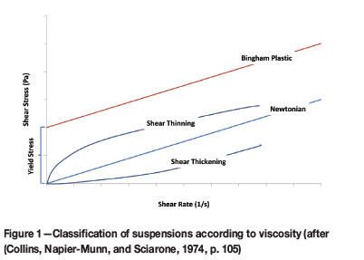
Ideal suspensions occur when the shear stress is directly proportional to the shear rate, and these are known as Newtonian fluids. Water is a Newtonian fluid with a viscosity of 1 centipoise (cP) or 0.001 Pa.s. The effect of Newtonian fluids is constant and predictable as the viscosity does not vary with shear rate.
A Bingham plastic requires a certain amount of force (stress) to be applied before it starts shearing. This is known as the yield stress. Toothpaste is a common example of such a plastic. A certain force must be applied to the tube before the paste begins to flow.
In shear thinning suspensions, the viscosity decreases with increasing shear rate, and in shear thickening suspensions the viscosity increases with shear rate.
Tomato sauce is an example of a shear thinning suspension. When squeezed out a bottle, it will thin out and flow, but once on the plate, it will retain its shape. Wet sand completely soaked with water (as on a beach) is an example of a shear thickening suspension, which is why when you walk on it, a dry area appears under your foot.
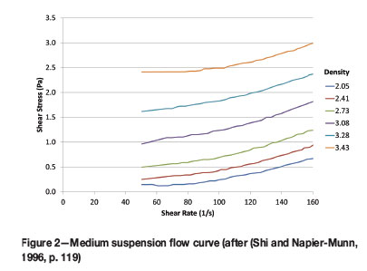
Heterogeneous suspensions such as those used for dense media tend to have a yield stress. The quantity of solid phase in the suspension is defined by the density of the suspension and is commonly referred to as the medium density. The flow curve for a given medium where only the medium density is varied is shown in Figure 2.
Apparent viscosity is defined as the viscosity at a given shear rate. The apparent viscosity curves corresponding to Figure 2 are shown in Figure 3.
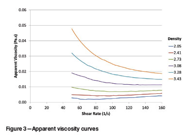
From the apparent viscosity curves, increasing the medium density leads to an increase in the viscosity. Depending upon medium density, the viscosity behaviour can range from shear thickening to Newtonian to shear thinning.
Medium viscosity and stability are directly related. High stabilities correspond to high viscosities and low stabilities correspond to low viscosities.
For high-density separations, i.e. greater than 2.6 t/m3, ferrosilicon is widely used. Ferrosilicon is a ferroalloy consisting of iron and silica in a very specific ratio. Although iron has a high particle density, it corrodes and in its pure form is not suitable as a solid phase in a suspension. Silica is added to improve the corrosion resistance of the iron. The only problem is that the more silica that is added, the lower the resultant density of the ferroalloy is. A silica content of 14-16% in the alloy has proven to provide the best corrosion protection without too great a reduction in the particle density (Collins, Napier-Munn, and Sciarone., 1974, p. 110).
Particle shape and particle size play an important role in the stability/viscosity of ferrosilicon suspensions (Collins, Napier-Munn, and Sciarone, 1976, p. 105).
Particle shape is a result of the production process. Milled ferrosilicon particles are angular in shape. Water atomization produces particle that are of a spherical nature. Gas atomization produces highly spherical particles. Example of the three particle shapes are shown in Figure 4.
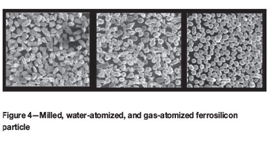
For the same particle size and suspension density, viscosity and stability decrease as the particle sphericity increases (i.e. when changing from milled to water-atomized to gas-atomized particles).
For each particle shape, there are a range of particle sizes. The maximum particle size is typically 212 µm. From a practical point of view, the percentage passing 45 µm is often used to differentiate size distributions. This is due to the fact that dry screening at 45 µm is quick and simple. Commercially available size ranges associated with the three particle shapes are shown in Figure 5.

Milled and water-atomized ferrosilicon cover similar size ranges, whereas the gas-atomized ferrosilicon is found in the middle of the range.
Separators
Separators can be divided into two main classes, i.e. static separators, in which the separation process takes place under the force of gravity (1 g), and dynamic separators where the separation takes place under the influence of multiple g forces. These multiple g forces are generated by accelerating the mixture of ore and medium within the separating vessel (Wills and Napier-Munn, 2006, p. 248).
Static separators
Although a wide range of static separating vessels have been used over the years, one of the more widely used units is the WEMCO drum. WEMCO is an acronym for the Western Machinery Company, which patented the WEMCO drum in 1954 (Maust, 1954). Drawings from the patent are shown in Figures 6 and 7.
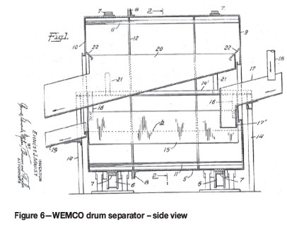

In the following description, the numbers in parentheses refer to the labels in Figures 6 and 7. In the WEMCO drum, ore and medium are introduced into the drum at the feed end (17). The drum shown in Figure 7 is rotating in a counterclockwise direction. The drum is fitted with lifters along the length of the drum (11). The heavier particles settle out and the lighter particles float. As the heavier particles settle to the bottom of the drum, they are trapped in the lifters, which carry them to the top of the drum. At the top of the drum they fall under gravity into the sinks launder (20). Medium is added to the sinks launder to flush the heavy particles out of the drum. The lighter particles float to the top of the medium and are carried out of the drum with the medium flow through the outlet (19). The floating particles are kept away from the lifters by skirts (15).
The distance from the bottom of the drum to the level of the medium in the drum (indicated by the symbol b) determines the maximum distance that the particles must travel to sink or float. Common practice is to feed the particles into the drum at half this distance, thereby ensuring that the distance that the heavier and the lighter particles must travel is the same.
The ferrosilicon particles in the medium suspension are subject to gravity and tend to settle out of the water suspension. The mixing action caused by the lifters as they slowly move through the medium helps to offset this to a degree, However, if the size distribution of the ferrosilicon is too coarse, settling will occur and an unstable medium with resultant efficiency losses will result. On the other hand, if the size distribution is too fine, the medium will become too viscous and efficiency will also be adversely affected.
Dynamic separators
A number of dynamic separators have also been used over the years, but the unit that is most widely used is the dense medium cyclone. It was first patented in 1942 by the Dutch State Mines and is often referred to as the DSM cyclone. A drawing from the original patent (Driessen, Krijgsman, and Leeman, 1951) is shown in Figure 8.
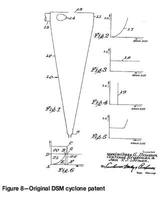
What is interesting to note is the lack of a vortex finder in the cyclone. This was introduced in 1948.
In the cyclone, a mixture of ore and medium is introduced into the feed inlet (15) under pressure. The pressure is supplied by either gravity or a pump feed. As the mixture enters the cyclone, the cylindrical inlet head (11) forces it to start rotating. As it rotates the ore is subject to a centrifugal force, which causes the larger and heavier particles to move to the outer wall of the cyclone, from where they are discharged through the spigot or apex of the cyclone (16). The finer and lighter particles are carried to the overflow (13) via the vortex finder.
An important point is that the ferrosilicon particles, which make up the solid phase of the medium suspension, are also subjected to the centrifugal force. This force classifies the ferrosilicon, with the coarser particles reporting to the cyclone underflow and the finer particles to the cyclone overflow. As a result, the cyclone overflow is of a lower density than the feed medium and the cyclone underflow is of a higher density. The differences in medium densities for the three cyclone streams are known as differentials. If the differentials become too large, the medium within the cyclone becomes unstable and efficiency is adversely affected. This occurs when the size distribution of the ferrosilicon is too coarse. On the other hand, if the size distribution is too fine, the medium will become too viscous and efficiency will also be adversely affected. In this case the differentials, especially between feed and overflow, reduce to zero i.e. the feed and overflow medium densities are the same.
Modelling separation
For both static and dynamic separators, separation is a result of particles moving through the medium. Modelling this process is different for static and dynamic separators due to the nature of the separators and the magnitude of the gravitational force that is applied to the separator.
Static separators
In the Stokes regime, the terminal or free settling velocity of spherical particles in fluids of known density and viscosity can be described by the following equation (Fuerstenau and Han, 2003, p. 174):
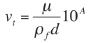
where
vt - terminal or free settling velocity (cm/s)
µ - fluid viscosity (cP)
pf - fluid density (g/cm3)
d - particle diameter (cm)
A - Archimedes number, which is given by:
ρs - particle density (g/cm3)
g - acceleration due to gravity (cm/s2)
Particles do not reach their free falling or terminal settling velocity instantaneously, but experience an initial period of acceleration until the terminal velocity is achieved.
The particle velocity as a function of time can be described by:
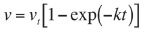
with
v – velocity (cm/s)
k is given by:

r – particle radius (cm)
The time required to achieve the terminal settling velocity is a strong function of the fluid density and viscosity as well as the particle size.
Free settling occurs when the volumetric concentration of particles in the fluid is less than 1%. If the concentration is higher, the particles interfere with one another and the settling rate is reduced. This is referred to as hindered settling. A correction factor CF can be applied to the free settling velocity vF to account for this reduction and calculate the hindered settling velocity vH.
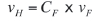
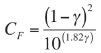
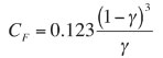
The correction factor for hindered settling is a function of the volumetric concentration (γ) of the ore in the ore/medium mixture. The factor is a function of the volumetric fraction (γ):
For γ < 0.3:
For 0.3 < γ < 0.7
Dynamic separators
The simplest model for particle motion in a dynamic separator such as a cyclone is given by the equilibrium orbit theory (Wills and Napier-Munn, 2006, p. 216).
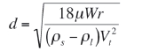
where:
d - particle diameter (cm)
ρs - particle density (g/cm3)
ρl - liquid density (g/cm3)
Vt - tangential velocity of the particle (cm/s)
r - radius of the equilibrium orbit (cm)
µ - liquid viscosity (cP)
W - radial velocity (cm/s).
Unfortunately, this simple model is not of great value as the practical determination of the radial and tangential velocities and the radius of the equilibrium orbit for a given cyclone geometry and operating conditions is problematical.
Of all the classification cyclone models that have been formulated since the 1950s, the two that remain the most widely used are the Plitt model and the Nageswararao model. These models are semi-empirical in nature and are the result of applying regression analysis to measured data. The influence of viscosity has been studied and the results have incorporated into a modified Plitt model with the following result (Kawatra, Bakshi, and Rusesky, 1996, p. 46):
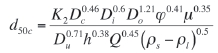
where
d50c - particle size with an equal chance of reporting to either cyclone underflow or overflow (µm)
K2 - calibration factor
Dc - cyclone diameter (cm)
Do - vortex finder diameter (cm)
Di - inlet diameter (cm)
Ψ - % volumetric solids in the cyclone feed
µ - liquid viscosity (cP)
Du - underflow or spigot diameter (cm)
h - free vortex height (cm)
Q - cyclone volumetric flow rate (l/min)
ρs - particle density (g/cm3)
ρl - liquid density (g/cm3).
Summary and comparison of models
The models can be summarized and compared using the following factors.
Medium phase
For both models, this is described by the following parameters:
ρ1 - the medium density (g/cm3)
µ - the medium viscosity (cP)
Geometry
For the static (drum) model, the distance that a particle has to move to become either floats or sinks is the major variable. For modelling purposes, it is assumed that the feed is introduced halfway between the level of medium in the drum and the bottom of the drum. The distance that a float and a sink particle have to travel is the same and equal to half the distance between the level of medium and the bottom of the drum. The primary variable is therefore drum diameter.
The drum length, as it determines residence time, is the secondary variable.
For the dynamic separator (cyclone), the geometry is uniquely defined by the following parameters:
►Cyclone diameter
►Inlet diameter
►Vortex finder diameter
►Barrel section (defined by barrel length)
►Cone section (defined by internal cone angle)
►Spigot diameter.
In the absence of detailed cyclone drawings, the free vortex height (h) can be approximated by the distance from the bottom of the inlet head to the spigot.
Operational
For the drum, the main operational parameters are circulating medium density and residence time.
For the cyclone, the main operational variables are circulating medium density and inlet pressure or head.
Viscosity determination
The determination of the viscosity of settling slurries, regardless of whether the solid phase is an ore or ferrosilicon, remains a major problem.
Viscosity measurement
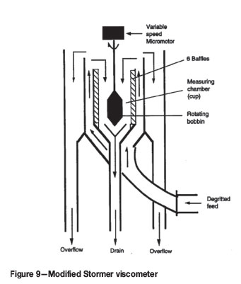
Although a number of different methods have been tried, the one that is most applicable to dense media in general and ferrosilicon in particular is that developed by Frank Shi while working at the Julius Kruttschnitt Mineral Research Centre in Australia (Shi and Napier-Munn,1996, p. 118).
The concept was originally developed by the De Beers Research Laboratory and makes use of a modified Stormer viscometer as shown in Figure 9.
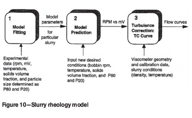
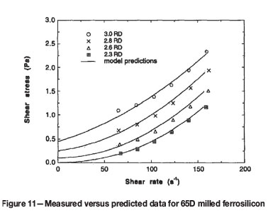
The concept was then taken further by Shi, who developed a model whereby the shear rate/shear stress relationship for a given medium can be modelled using the particle size distribution (laser-based p80 and p20), shape (milled or atomized), temperature, and medium density as inputs.
The model is summarized graphically in Figure 10. Measured versus predicted data for 65D milled ferrosilicon is shown in Figure 11.
Stability measurement
The stability of medium suspensions is also used as an indication of viscosity.
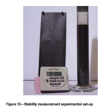
The test is very simple to conduct and does not require expensive laboratory equipment. The procedure is as follows:
► In a 250 ml measuring cylinder, make up 250 ml of medium at the required density
► Seal the top of the measuring cylinder and invert it 10 times to ensure that the medium is well mixed
► Place the measuring cylinder right side up on a table
► Track the mudline (interface between the medium and water) and record the time as it passes each gradation on the cylinder (on a standard 250 ml measuring cylinder, each gradation is 1 mm, but it is worthwhile checking)
► Plot the results on a graph and determine the slope of the resultant line where it is linear. The slope is the stability value.
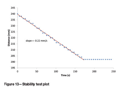
The experimental set-up is shown in Figure 12. A typical result is shown in Figure 13.
Medium selection
Static (drum) separators
The science
The model that has been described includes a medium density and a viscosity term. Provided that the medium is relatively stable (i.e. does not settle too quickly), the density can be assumed to be constant throughout the separator.
In the derivation of the equations to model particle velocity, the viscosity term is based upon Newtonian slurry. Using Shi's slurry rheology model, the viscosity of a medium suspension can show Newtonian behaviour for a small range in density, but in general is either shear thinning or shear thickening depending upon the medium density. It also exhibits a yield stress.
If the medium in the static separator is exposed to a constant shear rate, then the apparent viscosity of the medium suspension for this shear rate can be legitimately used for the viscosity term in the model.
The assumption that a constant shear rate applies throughout the separator has yet to be proven, and appears to be unlikely. At the lifter/medium interface, the shear rate will certainly be different to that just below the surface of the medium.
It is thus not possible to directly use the Newtonian- based models for particle transport as a tool to predict the effect of different medium suspensions.
The art
From an operational point of view, it is fairly easy to determine if the medium suspension used in a static separator provides an acceptable separation. This is done by monitoring the quality of the product and waste streams and identifying misplaced material. Furthermore, by focusing on the performance of the finer particle sizes, the effect of the viscosity of the medium can be inferred. Increases in viscosity lead to greater increases in misplacement for finer particles compared to coarser particles, due to their lower particle mass.
Once the correct grade and density of medium suspension have been identified, a stability measurement can be performed and the settling rate determined. This settling rate can then be used as a parameter to indirectly control the viscosity of the medium.
Dynamic cyclone separators
The science
The viscosity-modified Plitt model was developed based upon the assumption that most mineral suspensions are Newtonian below 50% volumetric solids. The work done by Shi and his slurry rheology model have, however, proven this to be invalid for medium suspensions.
The shear rate within a cyclone can be described using the following equation (Kawatra, Bakshi, and Rusesky, 1996, p. 42):

where S – shear rate (S-1)
– rate of change of tangential velocity with changing radius.
The maximum shear rate has been shown to occur close to the vortex finder, and the value decreases as the medium suspension moves closer to the wall of the cyclone. This variation in shear rate within the cyclone makes it impossible to use a single apparent viscosity value (corresponding to a given shear rate) in the modified Plitt equation to predict the cyclone cut size or d50. However, if for a given medium grade and density the viscosity is close to Newtonian, this value can be used.
From the apparent viscosity curves generated by the Shi rheological model, there are a limited number of combinations of medium grade and density where this occurs.
The art
For a homogeneous medium, the feed, overflow, and underflow densities would be the same as there is no solid phase for the cyclone to classify. However, if this situation occurs with a medium suspension, it implies that the viscosity of the medium suspension is so high that the cyclone is unable to classify the solid phase of the medium.
Operating practice has shown that if this is the case, then the efficiency of separation of an ore within a cyclone is also adversely affected.
Practical experience has shown that if the difference in the density of the cyclone feed and cyclone overflow is less than 3%, the medium is too viscous and separation efficiency is adversely affected.
If the medium suspension fed to the cyclone is too unstable, it classifies to an excessive degree within the cyclone. As a result, a range of densities occurs within the cyclone, with the lowest being close to the vortex finder and cyclone overflow where the maximum tangential velocity occurs, and the highest density towards the wall of the cyclone and the underflow. This also adversely affects the separation efficiency as particles build up within the cyclone due to the large density differences, and when the cyclone becomes too crowded they split randomly to the overflow and underflow.
Once again, practical experience has shown that if the difference in the density of the cyclone feed and cyclone overflow is more than 12%, the medium is too unstable and separation efficiency is adversely affected. The result is shown graphically in Figure 14.
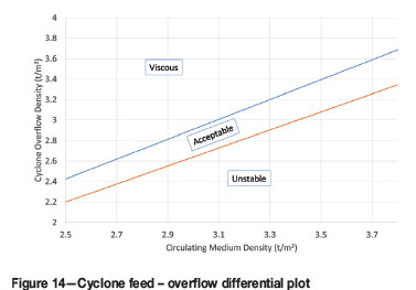
Based upon the above, the cyclone can thus be used as a viscometer to ensure that the grade of the medium suspension that has been selected is correct. This is done by measuring the difference between the cyclone feed and overflow densities and calculating the percentage difference. As long as this difference is maintained between 3% and 12%, the viscosity of the medium suspension will not adversely affect the separation efficiency.
Conclusion
Although models for particle movement in both static and dynamic separators are available, their derivation is based upon Newtonian rheology.
Using the only definitive predictive rheology model that is currently available, the Shi model, the rheology of medium suspensions is non-Newtonian and also has a yield stress. The existing models thus cannot be used to predict the effect of different medium suspensions for static and dynamic separators.
For static separators, one must rely on the stability measurement of medium suspensions that have already been proven by efficiency analysis to be applicable as an indirect measure of medium viscosity.
For dynamic separators, such as cyclones, the unit itself is used as a viscometer and the viscosity of the medium is inferred from the cyclone feed overflow differential.
Medium selection remains an art with a touch of science.
References
Collins, B., Napier-Munn, T.J., and Sciarone, M. 1974. The production, properties, and selection of ferrosilicon powders for heavy-medium separation. Journal of the South African Institute of Mining and Metallurgy, vol. 75, no. 5. pp. 103-105. [ Links ]
Driessen, A.G., Krijgsman, C., and Leeman, J.N.J. 1951. Process for the separation of solids of different specific gravity and grain size. US patent 2543689A. Directie Staatsmijnen Nl. [ Links ]
Fuerstenau, M.C. and Han, K.N. 2003, Principles of Mineral Processing. Society for Mining, Metallurgy, and Exploration, Englewood CO. [ Links ]
Grobler, J.D., Sandenbergh, R.F., and Pistorius, P.C. 2002.The stability of ferrosilicon dense medium suspensions. Journal of the South African Institute of Mining and Metallurgy, vol. 102, no. 2. pp. 83-86. [ Links ]
Gupta, A. and Yan, D. 2006. Mineral Processing Design and Operation: An Introduction. Elsevier Science. [ Links ]
Maust, E.J. 1954. Drum separator. US patent 2,696,300. Western Machinery Company. [ Links ]
Kawatra, S.K., Bakshi, A.K., and Rusesky, M.T. 1996. The effect of slurry viscosity on hydrocyclone classification. International Journal of Mineral Processing, vol. 48. pp. 39-50. [ Links ]
Shi, F.N. and Napier-Munn, T.J. 1996. A model for slurry rheology. International Journal of Mineral Processing, vol. 47. pp. 103-123. [ Links ]
Wills, B.A. and Napier-Munn, T.J. 2005. Wills' Mineral Processing Technology. 7th edn. Elsevier. [ Links ]

