


Servicios Personalizados
Articulo
 Inglés (pdf)
 Articulo en XML
 Referencias del artículo
Indicadores

Links relacionados
-
 Citado por Google
 -
 Similares en Google
Compartir

 Permalink
Journal of the Southern African Institute of Mining and Metallurgy
versión On-line ISSN 2411-9717
versión impresa ISSN 2225-6253
J. S. Afr. Inst. Min. Metall. vol.114 no.6 Johannesburg jun. 2014
GENERAL PAPERS
Design principles for optimizing an established survey slope monitoring system
N. Mphathiwa; F.T. Cawood
School of Mining Engineering, University of the Witwatersrand
SYNOPSIS
When slope angles are designed during open pit optimization, there is a risk factor applied in steepening the slopes. The steepening of slope angles has implications for the safety and economics of the mining operation. The steeper the slope angles, the greater the probability of slope failure. Although a slope failure will result in added costs, the challenge is to compile an accurate cost-benefit exercise optimizing the economic benefits of the project without exposing mine workers and equipment to unacceptable risk of rockfalls. A balance between the safety of the operation and the economics of the investment is therefore required. The ideal situation is to have a slope monitoring system that will predict slope failure by detecting any ground movement before the actual failure occurs. This early warning will allow the risk factor to be applied with a high degree of confidence, knowing that the risk will be adequately mitigated.
The objective of this paper is to provide guidelines on how to design an optimal survey slope monitoring system. It is the authors' view that for a survey monitoring system to yield desirable results, it should adhere to survey principles such as working from the whole to part and consistently cross-checking. The case study used is Jwaneng Mine, and the design strategy outlined can be used as a guideline for developing a new slope monitoring system or to optimize an existing one.
Keywords: open pit optimization, slope angle, slope failure, slope monitoring system design.
Introduction
Monitoring is defined as the regular observation of activities taking place in a project or programme, and is a process of routinely gathering information on all aspects of the project (Bartley, 2007). There are different types of monitoring surveys, but this paper focuses on slope stability monitoring. Slope stability monitoring can be defined as the science of measuring ground movements and detecting instability before failure occurs. Monitoring is an invaluable tool for assessing design performance and failure risk and for aiding risk minimization (Read and Stacey, 2009).
The objective of slope stability monitoring is to balance mine safety with the economics of the project. The safety of workers in any mining operation is the number one priority of every mining manager. This is both a moral and legal obligation. It is, therefore, critical to have a reliable slope monitoring system so that any potential failure can be detected well in advance, allowing for workers and equipment to be evacuated promptly from the hazard areas. The steepening of slopes results in less waste rock stripping, and hence reduces the costs of mining significantly. However, by steepening the slopes, the probability of slope failure is increased. This risk associated with the steepening of slopes is mitigated by slope stability monitoring. It follows, then, that the more reliable the slope monitoring system, the more risk can be taken when designing the slopes, hence reducing the cost per ton mined further. It is expected that, in the near future, data from slope monitoring equipment will add a much-needed dimension to slope engineering, when used to improve slope designs and to optimize slope angles (Cawood and Stacey, 2006).
Slope failures can also result in ore dilution when sliding waste rock mixes with the ore. This will inevitably reduce the grade and increase mining and treatment costs. A rockslide at Kumtor gold mine in Kyrgyzstan resulted in 100 000 ounces being cut from the 2006 production forecast (Mining News, 2006). The slope monitoring system allowed the area to be safely evacuated in advance, and there were no injuries, although a diamond drill was covered by rock. It is the authors' opinion that the design of the slope monitoring system is the determining factor in setting up a reliable early warning.
In this paper, the authors will attempt to answer the fundamental question of how to design a slope monitoring system? The focus will be on geo-referenced systems, otherwise known as survey slope monitoring systems. These systems include, among others, the Geodetic Monitoring System (GeoMos), slope monitoring radar (SSR), and the global positioning system (GPS) technology. The introduction of automated slope monitoring systems was a major step in optimizing the whole concept of monitoring. However, in the authors' opinion, no matter how sophisticated the instrumentation or the software is, if the foundation or design is not optimal, the level of confidence in the monitoring results will be low. This paper will be of interest to professionals involved in open-pit mining, including mine surveyors, mine planners, geotechnical engineers, mine safety officers, and all employees working in open-pit operations.
The case study
Jwaneng Mine, which is owned by Debswana Diamond Company, is used as a case study. Jwaneng Mine is currently extending its open pit mining through its Cut 8 project (Debswana, 2010), which will deepen the pit from 330 m to 624 m, with a length of 2.7 km and width of 1.7 km. A prefeasibility study is being undertaken for a Cut 9 project, which will deepen the mine further to 850 m, with a possibility of extending the dimensions of the pit further with a Cut 10 project (Mining Weekly, 2010). The deepening of the pit and the general increase in the footprint increases the risk associated with slope failures. The Cut 8 mining limit will be approximately 100 m from the main treatment plant infrastructure. Movement of the ground in the vicinity of the plant infrastructure can result in production losses for the company and significant unplanned replacement or repair costs. The abovementioned scenarios call for a robust slope monitoring system design to successfully mitigate the risk of slope failure.
In this paper, we assess the existing slope monitoring design at Jwaneng Mine and develop recommendations in order to make it optimal. Jwaneng Mine has been running a slope stability monitoring programme since 1989. In 1995, there was a proposal to upgrade the monitoring programmes at the Letlhakane, Jwaneng, and Orapa diamond mines (Watt, 1996). The focus was on the actual monitoring using conventional survey instruments such as the Wild DI 2202, precise levelling, and the calculation of the survey observations to reduce them to useable information. Most of the recommendations were implemented by all the three Debswana mines, and benefits were realized at that time. However, with the passage of time, developments have increased the need for a different approach to monitoring. The mines have gone deeper and wider with mining of additional cuts. For example, the Cut 8 limit at Jwaneng Mine is less than 100 m from the plant infrastructure. These developments, especially the deepening of the pits, have increased the risk associated with slope failure. To mitigate this heightened risk, Debswana responded by intensifying the monitoring and by increasing the number of targets and the frequency of the monitoring.
Debswana introduced automated monitoring systems in 2001, and has been gradually updating them at all of its mines. The GeoMos system was introduced to the company and implemented at the Letlhakane Mine in 2002, followed by Orapa and Jwaneng Mines. Similarly, SSR was first implemented at Jwaneng Mine in 2005, followed by Letlhakane and Orapa. Jwaneng has recently started installing GPS receivers in and around the pit to enhance the existing monitoring systems to mitigate the heightened risk of mining Cut 8.
Survey monitoring design considerations
The following design parameters of survey monitoring systems were considered:
Survey control network
This is the basis of the design. The integrity of any survey measurements depends on the accuracy of the survey control network. In the case of slope stability monitoring, all movements are referenced to the survey control network.
The first set of survey stations to be installed consists of primary beacons. The optimal distance of the primary beacons from the pit rim must be determined systematically. The positioning of the secondary beacons with respect to the monitoring site should also be established.
Construction of the survey beacons
> Primary beacons-the stability of primary beacons is critical because they are used as reference stations for orientation and to determine the position of the monitoring station when using the GeoMos
> Secondary beacons-the secondary beacons are constructed close to the rim of the pit so that there is a clear line of sight to the monitoring targets. Although the secondary beacons' stability is inevitably affected by blast vibrations, because of their close proximity to the pit, there is need for a structural design that can withstand blast vibrations as much as possible
> Instrument shelter-the construction of the shelter for housing the monitoring equipment should be investigated. Instruments must be well protected against corrosion, moisture, other aggressive agents, and vandalism (Abramson et al., 2001). The shelter protects the instrument from mining conditions such as dust and flying rocks. However, the materials used must not compromise the accuracy of the monitoring measurements.
Equipment election
The choice of equipment depends primarily on the required accuracy, and also the type of movement to be detected. Some instruments such as levels are good for vertical movements, while others, such as global positioning systems, are suitable for horizontal movements. The authors investigated ways to utilize different monitoring equipment to complement each another.
Software selection
The focus is on how to analyse and present data from various monitoring systems. Most monitoring systems are equipped with software for interpreting and presenting results. The aim is to investigate ways of integrating data from these different systems to ease the flow of information.
Skills and competencies
For the design to produce desired results, it is imperative to have people with right skills and competencies to implement and maintain it. It is recommended that a qualified and competent person should oversee the slope monitoring programme and conduct the data analysis (Jooste and Cawood, 2006).
Optimization of a typical monitoring system
The optimization strategy will consider the following parameters.
Control network design
The survey control network design process is as outlined as follows:
> A desktop exercise to determine the provisional positions of the survey beacons
> Determination of lines of sight to be used during geodetic surveys
> A reconnaissance to adjust the provisional positions to more practical positions
> Computation of observations from coordinates using survey applications such as resection
> Tests of the network accuracy by computing standard deviations of coordinates calculated from redundant observations (Kealey, 2004).
The provisional positions of the primary beacons are established using the principle of locating the primary control points anywhere from 100 m to 3 km away from the pit rim (Cawood and Stacey, 2006). Figure 1 shows conceptual positions of the primary beacons established from a desktop study.
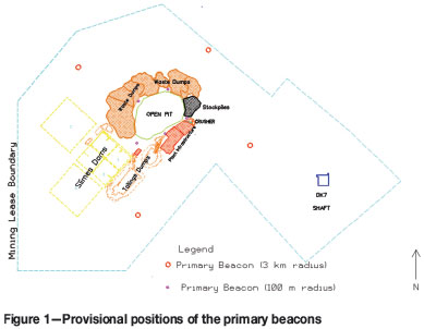
The design entails two sets of primary beacons. The first set of primary beacons will be positioned 100 m away from the pit. The build-up of dumps and infrastructure around the pit is a constraint in placing the primary beacons further away because this will affect the line of sight. This set of primary beacons (100 m radius) is used for orientation during geodetic monitoring. It is also used to check and update the position of the monitoring beacon using the resection method, known as the free station in GeoMos. The first set of primary beacons, 100 m away from the pit rim, is not be very stable as it is affected by blast vibrations. It is, therefore, critical to regularly update the beacon positions using the GPS post-processing method. The second set of primary beacons (3 km radius) is logged as known points when applying the post-processing method, as these beacons are more stable.
The secondary beacons will be constructed on the rim of the pit. The guiding principle is to maximize the view onto the pit (Bannister Raymond, Baker, 1998). The current GeoMos design at Jwaneng mine requires only two secondary beacons to be used as monitoring beacons. However, additional secondary beacons should be built in case there is loss of line of sight to one of the monitoring beacons or the stability of the ground they are built on is compromised (Cawood and Stacey, 2006).
Beacon design and construction
After completion of the design of the survey control network, the focus now shifts to the beacons' structural design and construction. There are four fundamental questions to consider when designing and constructing survey beacons:
> Is the beacon design compatible with geotechnical properties of the ground on which the beacon will be constructed?
> Is the design easy to implement?
> How will the designer ensure that the structure is implemented as designed?
> Does the contractor have the right competencies to implement the design specification adequately?
The structural design of the survey beacons is appropriate for the Jwaneng Mine stratigraphy. The 17-20 m top layer of sand has been designed for by incorporating piling to ensure the foundation of the beacon is built on solid rock. Piling is highly recommended when the bedrock is covered by less competent material, such as sand (Leica Geosystems. 2004). The construction notes explaining how the design should be implemented are clear and easy to understand, making the design easy to implement. It is advised that the construction specifications be made simple to interpret.
To ensure that the beacon design is constructed to the correct specification, the company needs to consider the following:
> When evaluating tenders for the construction of the beacons, more weight should be given to the technical competencies of the company rather than general practice of giving the lowest bidder more points
> There is need for a construction schedule to accompany the structural design. The construction schedule should have gate release clauses stating stages of construction where progress cannot be made to the next stage until the built structure has been inspected and signed off by the relevant personnel.
Instrument shelter
The next design aspect to consider is the instrument shelter that houses the Total Station when using the GeoMos for monitoring. The purpose of the shelter is to protect the instrument from theft, dust, rainfall, and flying rocks from blasting activities. When designing the instrument shelter, construction material that will not affect the accuracy of the measurements must be used. Figure 2 shows a typical design of an instrument shelter.
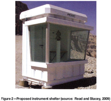
The glass allows the Total Station to sight to any beacon or targets within its line of sight without hindrance from the shelter. Jwaneng Mine has experienced problems with measuring through glass as it was affecting the accuracy of monitoring results. Glass with a thickness of 3 mm or less has a minimal impact on the accuracy of the measurements, and the errors can be adjusted using a tested formula. Tint and shape also matter, since clear flat glass has the least impact (Afeni and Cawood, 2010).To protect the glass from flying rocks during blasting, the shelter can be equipped with pull-down rubber curtains that can be pulled down during blasting.
Selection of monitoring instrumentation
After constructing the infrastructure, such as control survey beacons and the housing of the instrument, the next design process involves the selection of suitable monitoring equipment. The selection process takes the following factors into consideration:
> The expected magnitude of the ground movement
> Most likely movement direction (horizontal or vertical)
> Accuracy and precision of the instrument
> Number and frequency of measurements
> Size of area to be monitored
> Level of automation
> Ease of interface with other monitoring instruments
> GIS adaptability (Cawood and Stacey, 2006).
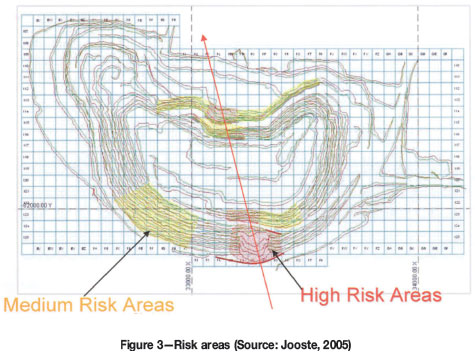
The monitoring process should be started by the identification of risk areas by the geotechnical engineers (Jooste, 2005). The areas are then classified according to the severity of the risk (high, medium, and low) as shown in Figure 3. The severity of the risk is one of the determining factors in equipment selection.
Jwaneng mine has two Total Stations connected to the GeoMos, two SSRs, six GPS receivers, one digital level, and one GPS/GNSS surveying system as part of the slope stability monitoring equipment. This combination of equipment can provide an optimal monitoring solution if it is appropriately utilized.
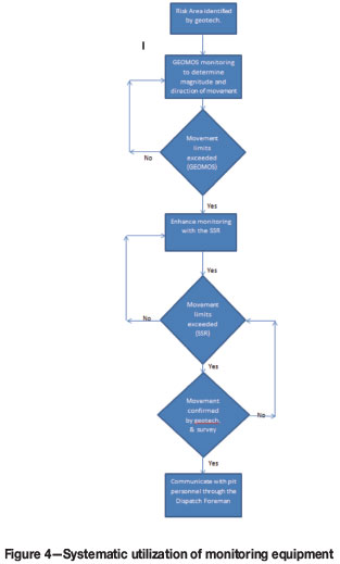
Two Total Stations, which are components of the GeoMos, should continue to monitor either side of the pit. The GeoMos primarily tracks the direction of movement, while the SSR is used to measure the magnitude. There needs to be a systematic link between the SSR and the GeoMos. For example, when specific movement limits are reached when monitoring with the GeoMos, monitoring can be intensified by incorporating the SSR. It has been suggested that before taking any actions when movement limits are reached, the responsible personnel should confirm that the cause is actual ground movement (Jooste, 2005). The systematic deployment of monitoring equipment is illustrated in Figure 4.
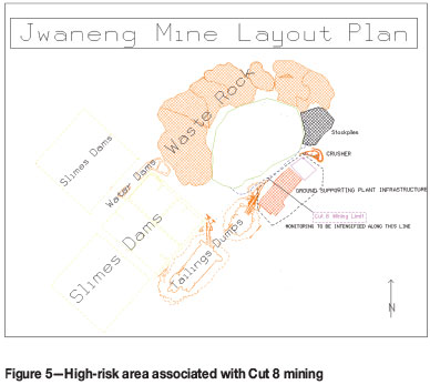
The area close to the Cut 8 mining limit has been identified as a high-risk area and its monitoring should be intensified by dedicating a SSR unit to monitor the highwalls continuously in the area, as shown in Figure 5. GeoMos targets should also be installed in the area to assist with establishing the direction of movement if detected. To enhance the monitoring further, GPS receivers should be installed on the highwall in that area to provide a cross-check to the GeoMos and the SSR. Cross-checking is a necessity in slope stability mornitoring (Abramson et al., 2001).
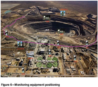
Since the main treatment plant infrastructure is within 100 m of the mining activities in Cut 8, the built-up area should be monitored for movement. The mine should consider installing GPS receivers in this area. The GPS receivers should be strategically positioned to avoid measurement errors brought about by multi-pathing and dilution of geometric intensity of satellites because of the plant infrastructure. Multi-pathing and satellite availability can be a problem when monitoring around tall structures using GPS receivers. To compensate for the inaccuracies of GPS height measurements, the mine should use the precise levelling method (Jooste, 2005). The challenge inherent in the precise levelling method is that it is a point measuring method and will not adequately cover large areas. To enhance the precise levelling method, the mine should consider other monitoring methods suitable for subsidence monitoring and which can cover large areas, such as InSAR technology. Portable ground technology that produces high-resolution SAR images is the most suitable equipment (Canuti et al., 2002). Figure 6 illustrates the proposed deployment of the monitoring equipment at Jwaneng mine.
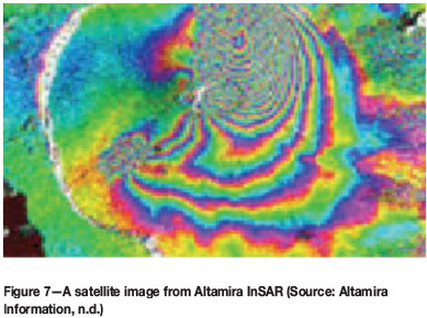
Satellite images from the InSAR technology should be used to reconcile the monitoring systems at Jwaneng Mine. The InSAR technology tracks the impact of ground movement on infrastructure around the pit, dumps, and slimes dams (Altamira Information, n.d.). Figure 7 shows an example of a satellite image produced from InSAR. The magnitude of movement is presented in colour fringes in the comparison of satellite images from different dates. The images should be purchased on a quarterly basis, but more frequently should there be a need. At the start of monitoring, archived images should be used to identify hazard areas based on historical movements.
Data collection and processing
This section discusses the data collection strategy suitable for Jwaneng Mine, focusing on the frequency of measurements and processing of the data for errors.
The frequency of the slope monitoring measurements should be systematic and guided by rock behaviour. The movement rate of the rock should determine the frequency of the measurements. The frequency of the measurement can be determined as follows;
> Movements of 0 to 2 mm per day are monitored once a month
> Movements of 0 to 5 mm per day are to be monitored once a week
> Movements of 5 to 10 mm per day to be monitored once every 2 days
> Movements of 10 to 50 mm per day will be monitored once per day
> Movements greater than 50 mm will require constant observation (Jooste, 2005).
The measurement guidelines stated above are as applied at Venetia mine. It is recommended that each mine develops its own guidelines suitable for local prevailing conditions.
The mine needs to be consistent with the checking of the positions of control points using the GPS post-processing method and precise levelling. These processes should be carried every six months as per survey procedures, and be repeated more frequently when movement limits are exceeded.
Analysis and reporting of monitoring results
The mine should consider the following aspects when selecting the appropriate software to be used to analyse and report slope stability monitoring results.
Since various instruments are used to collect slope stability monitoring data, there is need to integrate this data and analyse it from one point so that it can be subjected to the same level and standard of interpretation. If the data is analysed using the same software, it becomes easy to establish trends in data from different sources. Integration also allows for cross-checking between data sources (Abramson et al., 2001). Figure 8 illustrates how data from different sources can be integrated and the benefits derived.
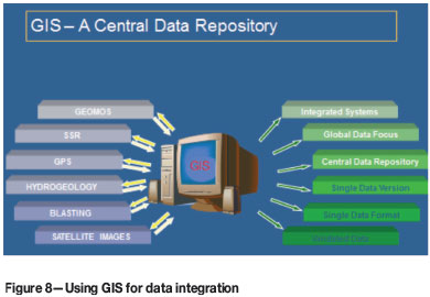
GIS is the most common software used to integrate data from various sources for analysis and presentation. Most GIS packages have least-square adjustment functionality for error analysis, graphic display functionality, and can produce movement graphs. GIS evolves with data collecting instruments, which makes it suitable for the ever-developing slope monitoring technology (Wolf and Ghilani, 1997). The other advantage of GIS is that because of its ability to handle large quantities of data, it can be used to manage other mine data such as rainfall figures, blasting data, pit dewatering information, and other hydrological data that has influence on the stability of pit slopes (Wolf and Ghilani, 1997).
Integration allows for data from the various monitoring systems to be interpreted, analysed, and movement trend comparisons done within a short interval after collection. If data is allowed to accumulate without analysis, the integrity of the monitoring process will be compromised.
Monitoring procedures
The next design criterion to consider is the monitoring procedures guiding the slope stability monitoring process. Jwaneng Mine procedures are categorized as follows:
Code of practice (COP)
All mines should develop a code of practice guiding slope stability monitoring. Although there are Acts guiding slope stability monitoring in Botswana, these are not very comprehensive. Such mines should look at Acts guiding slope stability monitoring in other countries for guidance, as the principles are the same. The South African Department of Mineral Resources (DMR) has prepared a guideline for the preparation of a COP to combat rockfall and slope instability-related incidents in open pit mines (Cawood and Stacey, 2006). The guideline is available on the website of the Department of Mineral Resources (DMR, 2005). In developing a COP, the mine could be guided by the following principles:
> Identification and documentation of rock-related incidents
> Development of appropriate strategies to eliminate or reduce risk caused by these hazards
> Allocation of duties for the execution of these strategies
> Training of personnel to enable them to carry out their duties (Gudmanz, 1998).
The COP should be reviewed regularly to keep up with international standards guiding slope stability monitoring.
Process flows
These procedures list the step-by-step processes of slope stability monitoring activities. Examples of these procedures include the GeoMos operating procedure, SSR operating procedure, precise levelling procedure, and the GPS post-processing procedure.
Warning systems and response
This focuses on the action that will be taken when ground movements have been detected. The mine will develop guidelines on how to respond to movements of different magnitudes. The procedures listed above should be tested for practicability by running mock-ups regularly.
The procedures must be stored in one place and made easily accessible.
Personnel responsibilities
After the slope monitoring system has been implemented and procedures developed, there is a need to consider the personnel who operate the system.
Geotechnical engineers are responsible for identification of hazardous areas and the classification of levels of risk. The level of risk determines the precision and the frequency of the measurements. The analysis and reporting of the monitoring results are also the responsibility of the geotechnical engineers.
Mine surveyors are responsible for managing and maintaining the slope monitoring equipment in terms of availability and utilization. Furthermore, the surveyors are responsible for managing the data acquired by the monitoring equipment. They ensure that the data is processed for errors before being plotted for analysis. The mine surveyors are also responsible for the maintenance of the survey network. This maintenance is done by regularly carrying out activities such as GPS post-processing and precise levelling. The management of slope stability monitoring procedures is a joint responsibility of the mine surveyors and the geotechnical engineers.
The information technology personnel are responsible for the security and backups of database storing the slope stability monitoring information. They ensure that the software used for analysis and the communication system used to relay slope stability information is always available.
After these responsibilities have been allocated, a competency matrix is developed for each individual involved in the slope stability monitoring process. The competency matrix is then used to assess the level of competency, which informs the development programme for the individual.
Budget
The mine needs to carry out a proper cost analysis to determine the cost implications. To justify the extra expenditure aimed at optimizing the existing design, the value-add of the new components should be clearly stated (Cawood and Stacey, 2006).
Conclusion
A strategy for optimizing slope monitoring process has been developed. The efficiency of the monitoring system should be gauged by its ability to predict failures and its economic value-add during slope angle design. The strategy focused on large open pit mines, with the Debswana Jwaneng mine serving as a case study,
It is concluded that slope monitoring requires a multi-faceted approach focusing on the survey control network, beacon design and construction, the equipment shelter, equipment selection, data collection and processing, procedures, and personnel responsibilities. All of these factors are equally critical for an optimal monitoring process. Negligence in one area can negate all the good work done in other strategic areas, leading to unreliable monitoring results.
It is evident that although slope monitoring has evolved over the years, with the process becoming more automated, basic survey principles such as working from whole to part, cross-checking, documentation of procedures, and error adjustment are still required for reliable results to be achieved. The amount of data that needs to be collected and analysed require a dedicated mine surveyor and a geotechnical engineer on a full-time basis.
Recommendation
In addition to the strategy outlined in this paper, it is recommended that further research be conducted in the following areas.
> The correction for varying atmospheric conditions brought about by depth changes in the pit remains a challenge when using GeoMos and need to be investigated. It is critical to understand what actually happens to the signal that travels from the Total Station to the monitoring point. Varying temperatures and atmospheric pressure, coupled with dust and fumes in the pit, affect the accuracy of distance measurements and need to be investigated
> It is essential to develop a systematic approach to managing the large amounts of data collected by the different monitoring systems so that a single version of the truth can be detected from them. This approach should encompass data validation, processing, and interpretation
> Beacon design and construction standards should to be developed. These standards will ensure that the reference points for monitoring are robust and not easily affected by blasting activities.
Challenges in the area of slope stability monitoring will always exist. The onus rests with mine surveyors and geotechnical engineers to turn these challenges into opportunities for continuous improvement. The current literature should be reviewed by the relevant parties, and they should participate in technical conference events.
References
Abramson, L.W., Lee, T.S., Sharma, S., and Boyce, G.M. 2001. Design, Construction and Maintenance. Slope Stability and Stabilization Methods. Wiley-Interscience, Hoboken, NJ. Chapter 8, pp. 604,607, 608-609, 626-627, 629. [ Links ]
Afeni, T.B. and Cawood, F. 2010. Do the properties of glass matter when taking Total Station distance measurements through an observation window? International Society for Mine Surveying XIV International Congress, Sun City, South Africa, 20-24 September 2010. p. 167. [ Links ]
Altamira Information. Not dated. Ground motion InSAR. www.altamira-information.com/html/1-18161-Techniques.php [Aaccessed 01/08/ August 2011]. [ Links ]
Bannister, A., Raymond, S., and Baker, R. 1998. Surveying. Pearson Education Limited. pp. 190, 207, 337-338, 431. [ Links ]
Bartley, P. 2007. The nature of monitoring and evaluation; definition and purpose. www.scn.org/cmp/modules/mon-wht.htm, [Accessed 27 July /7/2010]. [ Links ]
Canuti, P., Casagli, N., Moretti, S., Leva, D., Sieber, A. J., and Tarchi, D. 2002. Landslide monitoring by using ground-based radar differential interfer-ometry. Proceedings of the First European Conference on Landslides, Prague, Chech Republic, June 2002, pp. 523-527. [ Links ]
Cawood, F.T. and Stacey, T.R. 2006. Survey and geotechnical slope monitoring considerations. Journal of the South African Institute of Mining and Metallurgy, vol. 106, no. 7. pp. 495-497, 500-501. [ Links ]
Debswana., 2010. Jwaneng Long Term Plans. 2010. [ Links ]
DMR. 2005. Guideline for the compilation of a mandatory code of practice to combat rock fall and slope instability related accidents in surface mines. www.dmr.gov.za/guidance-notes-for-medical-practitioners/finish/20-mine-health-and-safety/350-combat-rockfall-and-slope-instability-related-accidents-in-surface-mines/0.html [Accessed 8 May 2014]. [ Links ]
Gudmanz, K.M. 1998. The implementation of codes of practice, Symposium on Rock Mechanics and Productivity and the Implementation of Codes of Practice. West Rand, South Africa, 28 October 1998. Handley, M.F. (ed.), South African National Group of the International Society of Rock Mechanics. pp. 3-6. [ Links ]
Jooste, M.A. and Cawood, F.T. 2006. Survey slope stability monitoring: Lessons from Venetia Diamond Mine. International Symposium on Stability of Rock Slopes in Open Pit Mining and Civil Engineering, Cape Town, 3-6 April 2006. pp. 361-363. [ Links ]
Jooste, M.A. 2005. Slope Stability Monitoring In Open Pit Operations. Investigational Project for Masters Degree in Engineering, University of the Witwatersrand, Johannesburg, 2005, pp. 16,27,36,37. [ Links ]
Kealy, A. 2004. 451-200 Survey Networks Theory, Design and Testing. Department of Geomatics, University of Melbourne, Victoria. www.geom.unimelb.edu.au/kealyal/200/Teaching/net_design_test.html [Accessed 13 December 2010]. [ Links ]
Leica Geosystems. 2004. Reporter, no. 50, Leica Geosystems, April 2004, p.12. [ Links ]
Mining News. 2006. Rockslide at Kumtor. www.miningnews.net//storyview.asp?storyid=62170§ionsource=s0. 19 July 2006, [Accessed 29 July 2009]. [ Links ]
Mining Weekly. 2010. Botswana, De Beers investing R25bn in ultra-rich Jwaneng Diamond Mine. www.miningweekly.com, 19 October 2010 [Accessed 25 November 2010]. [ Links ]
Read, J. and Stacey, P. 2009. Guidelines for Open Pit Slope Design. CSIRO Publishing, Collingwood, Victoria, Australia. pp. 342, 346-353. [ Links ]
Watt, I.B. 1996. Monitoring Surveys at Letlhakane and Orapa open pit mines. Consulting Report. March 1996. [ Links ]
Wolf, R. and Ghilani, D. 1997. Adjustment Computations: Statistics and Least Squares in Surveying and GIS. John Wiley and Sons, Hoboken, NJ. pp. 1-11. [ Links ]

