


Services on Demand
Article
 English (pdf)
 Article in xml format
 Article references
Indicators

Related links
-
 Cited by Google
 -
 Similars in Google
Share

 Permalink
Journal of the Southern African Institute of Mining and Metallurgy
On-line version ISSN 2411-9717
Print version ISSN 2225-6253
J. S. Afr. Inst. Min. Metall. vol.113 n.8 Johannesburg Jan. 2013
CONFERENCE
Fundamentals of designing refractory linings for hydrometallurgy autoclaves
A. Koning
Hatch Associates, South Africa
ABSTRACT
Pressure hydrometallurgy operations require vessels to be lined with an impermeable membrane for corrosion protection and one or more courses of refractory or ceramic brick. Examples of unit operations that utilize composite lining systems include pressure oxidation autoclaves, sulphide precipitation autoclaves, chloride leach reactors, flash vessels, cyclone separators, and direct contact condensers (heater vessels and quench vessels). The refractory lining must satisfy multiple requirements: it must thermally insulate the membrane from process fluid, be structurally stable, provide erosion resistance, be chemically compatible with process fluid, and provide an economic service life.
New hydrometallurgical processes are pushing the pressure, and temperature with each new generation of plants. A fundamental understanding of all factors affecting the mechanical stability of the lining system is essential as lining designs move further away from the industry's experience base.
The method of designing a refractory lined vessel is examined taking into account the impact of irreversible chemical swell, operating factors, design factors, and installation factors. The effect of geometry and incorporating additional degrees of freedom to the analysis is explored using two-dimensional and three-dimensional finite element analysis (FEA). The effect of these additional degrees of freedom on the results of the one-dimensional model are discussed.
Keywords: refractory lining design,autoclave, finite element analysis.
Introduction
Mechanical stability
Once candidate lining materials have been selected based on chemical stability in the process environment, the designer must ensure that the lining system is mechanically stable. Mechanical stability is traditionally determined by ensuring that the hot face refractory layer is in compression through all operating conditions and that the stresses do not exceed the material's failure strength.
An equally important consideration is the calculated overlap between the brick lining and the membrane. This new stability factor requires that the overlap should be positive, that is, that the steel shell should be in contact with the refractory lining throughout all operating conditions. A negative overlap (i.e. gap) between the brick lining and the membrane could have the following consequences:
Liquid can accumulate in the gap; rapid depressurization could vaporize this liquid, leading to high stresses on the back of the brick lining
Based on these mechanical stability criteria, the component strains and stresses must be calculated for all operating conditions. This is undertaken first in one dimension, then as required, in two and three dimensions to account for more complicated shapes.
One-dimensional spreadsheet model
Initially in the design process, one-dimensional thermal conduction and stress analyses are completed with a spreadsheet based on classic stress models. Some of the parameters considered for the one-dimensional analysis include:
The one-dimensional spreadsheet model allows many parameters to be evaluated quickly. A wide variety of variables can be changed independently. The spreadsheet provides the following benefits:
The approximate thicknesses of the refractory are determined within the one-dimensional spreadsheet prior to proceeding with FEA modelling.
The use of FEA in vessel design
One-dimensional calculations assume a cylindrical vessel lining that is thin relative to the radius of the vessel. The addition of attachments, supports, nozzles and hemi-heads, or thick-walled vessels to the analysis requires considerably more complex mathematical analysis. A designer must resort to finite element analysis (FEA) in these cases as exact formulae are difficult or impossible to obtain. FEA increases the number of degrees of freedom of the one-dimensional analysis by allowing heat to flow in multiple directions and allowing the material to move in multiple directions. An FEA analysis will highlight hot-spots in the vessel or stress concentrations that will lead to failures. The designer can then focus on these hot-spots or stress concentrations and parameters such as gaps, geometry, and material selection in order to eliminate the hot-spots or stress concentrations.
Two-dimensional FEA analysis
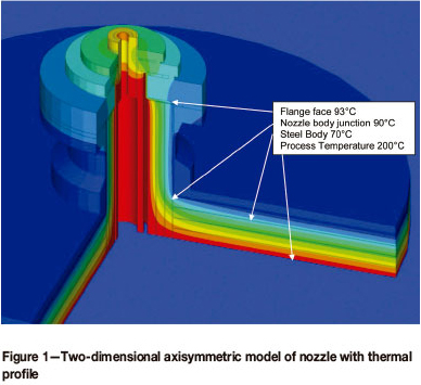
The primary drawback to a full three-dimensional FEA model is that it is more time-intensive than one-dimensional analysis, as a geometry must be built in three dimensions and meshed. An intermediate step between the one-dimensional analysis and the full three-dimensional analysis is a two-dimensional axisymmetric model, where the geometry and boundary conditions are assumed to be revolved 360° about an axis. This model is relatively easy to construct and is used primarily to determine nozzle sizing and insert layout before proceeding to a three-dimensional model. A typical axisymmetric model for a nozzle is shown in Figure 1. In this example the membrane temperature varies from 93°C on the flange face to 90°C at the nozzle and vessel body interface to 70°C within the vessel body. A designer can modify the thickness and type of materials used and their location to reduce these temperatures to acceptable levels.
Three-dimensional FEA analysis
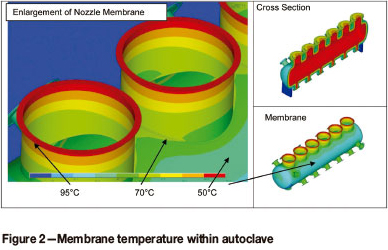
Once the vessel has been sized in accordance with code requirements and the nozzles have been sized in accordance with process flow, thermal membrane temperature, and code requirements in a two-dimensional analysis, a full three-dimensional model is created. In Figure 2 the geometry of a horizontal autoclave operating at 200°C is shown with its associated mesh. The model consists of steel, membrane, gap, and brick materials. With the three-dimensional model, interferences between components and weights of the different components are easily calculated.
In order to determine the thermal profile within the vessel, material properties and thermal loads are assigned. The thermal conductivity of each of the materials is entered as it varies with temperature. When the thermal model is solved, the thermal conductivity of the material at a particular location is based upon the temperature of that material at that location. The convection coefficient on the inside and outside is also varied with the temperature of the surface that the heat is flowing from or into. With thermal imaging we can calibrate the material properties and loading conditions. For known materials, the results of thermal FEA analysis are extremely accurate.
Owing to the three-dimensional nature of the model below, heat flows towards the junction between the nozzle and the vessel body from the inside of the nozzle and the vessel itself. It is because of the heat flux coming from multiple directions that we see an increased temperature at the junction between the nozzle and the vessel body. In addition, the proximity of nozzles to each other allows heat to come from adjoining nozzles which creates localized hot-spots between the nozzles. In Figure 2, although the vessel body temperature is 50°C, the junction between the nozzle and the vessel body is at 70°C. The designer is at liberty to move nozzles and change materials and thickness in order to reduce these localized hot-spots.
With the addition of heat capacitance the model can be solved in a transient manner in order to determine the heat-up time required. The transient model and the thermal model are subsequently used in the stress analysis.
Once the thermal analysis has been completed, the mechanical properties varying with temperature are placed in the model. Loads or combinations of loads including piping loads, gravity, hydrostatic head due to vessel contents, internal pressure or vacuum, thermal expansion, and swell are applied to the mesh and the stresses and distortions within the vessel are calculated.
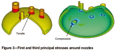
In the vessel shown in Figure 3 the stress analysis reveals that there are localized compressive stress concentrations on the hot face of the nozzle/body juncture in the brick lining. There are also tensile localized stresses between the nozzle and body on the cold face. This is confirmed by inspections of failed brick linings. The use of thicker shell materials instead of repads, gaps, and self-reinforced nozzles can help to reduce these stresses.
DIN 28 060 stipulates the dimensional tolerances for brick-lined vessels. This standard is very useful for determining the allowable distortions in the fabricated vessel, but does not take into consideration the distortions resulting from the applied loads, which can be several magnitudes higher that the DIN 28 060 standards. In addition, the ASME code will provide a vessel which is acceptable, but due to steel stress and fatigue levels may not provide a uniform support frame for the brick lining. An area of interest is the knuckle in a hemi-head. The knuckle is a high stress area for the vessel and is often allowed to yield during hydrotesting. The distortion of the steel shell in the knuckle can compound the already high stresses in the brick lining. The use of thicker shell materials instead of repads in the head of the vessel can reduce the stresses in the knuckle area of the vessel.
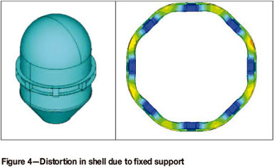
In addition to the nozzle and vessel-body juncture, the head and supports are known to be localized points for frequent brick-lining failures. These failures can be attributed to the vessel steel shell restraining the brick lining unevenly, which causes excessive tensile stresses on the cold face of the brick lining and compressive stresses on the hot face. In Figure 4, for example, a vessel is supported at eight locations by a ring beam. If the support points are not allowed to expand with the addition of thermal expansion and pressure the vessel will not deform uniformly. This would in turn cause stresses on the lining. These stresses on the lining can be reduced with the use of gaps, sliding supports, or different geometries for the support. Similar effects are seen with saddle supports around horizontal autoclaves.
FEA allows the designer to compare different materials and geometries to determine the primary stressors for the lining system. To aid in these comparisons the models are built parametrically. Through these comparisons, the dependence of the model results on geometry and material can be determined. In particular, while the material properties for steel are well known, the material properties for ceramics, especially chemical swell, are not well documented. This will lead to inaccuracies in the magnitudes of the stresses, but will still allow one to compare different designs and then select the best designs given all material properties being the same. After the vessel has been built, the model can be calibrated with strain gauges attached to the vessel steel shell and then compared to the calculated values.
Conclusions
With the aid of computers, more comprehensive calculations are being completed prior to the construction of brick-lined vessels. The use of FEA has given the designer a way of predicting thermal profiles more accurately than the classical one-dimensional analysis. The use of gaps, swell, and three-dimensional geometry can now be balanced to engineer a more stable and reliable brick lining system.
References
Falcke, F.K and Lorentz, G. 1985. Handbook of Acid-Proof Construction. VCH Verlagsgesellschaft, Weinheim, Germany, pp.163-171. [ Links ]
Koning, A. and Lauzon, P. 2004. Design fundamentals for hydrometallurgy pressure vessel refractory lining. Pressure Hydrometallurgy 2004: 34th Annual Hydrometallurgy Meeting of CIMI. Papangelakis, V. and Collins, M. (eds).: Canadian Institute of Mining, Metallurgy and Petroleum. Montréal. pp. 617-638. [ Links ]
Lauzon, P., Koning, A., and Donohue, I. 2008. Stress development in refractory due to the rate of temperature change: a pressure vessel refractory lining consideration. Southern African Hydrometallurgy Conference 2009. Southern African Institute of Mining and Metallurgy, Johannesburg. pp. 57-64. [ Links ]
© The Southern African Institute of Mining and Metallurgy, 2013. ISSN 2225-6253.
This paper was first presented at the, Refractories 2013 Conference, 23-24 April 2013, Misty Hills Country Hotel and Conference Centre, Cradle of Humankind, Muldersdrift, South Africa.

