


Services on Demand
Article
 English (pdf)
 Article in xml format
 Article references
Indicators

Related links
-
 Cited by Google
 -
 Similars in Google
Share

 Permalink
Journal of the Southern African Institute of Mining and Metallurgy
On-line version ISSN 2411-9717
Print version ISSN 2225-6253
J. S. Afr. Inst. Min. Metall. vol.113 n.8 Johannesburg Jan. 2013
CONFERENCE
Integrated production of liquid sulphur dioxide and sulphuric acid via a low-temperature cryogenic process
M. Verri; A. Baldelli
Desmet Ballestra S.p.A
ABSTRACT
The paper describes the design options available for the simultaneous production of liquid sulphur dioxide, via cryogenic condensation, and sulphuric acid in a sulphur-burning sulphuric acid plant. The impact of the operating conditions of the cryogenic condensation on plant capital and operating costs are discussed, with the main focus on the optimization of the most important economic and operative drivers of the non-ferrous mining industry, such as energy efficiency, reliability, and availability. A case history relevant to an integrated sulphur-burning plant producing liquid sulphur dioxide and sulphuric acid, recently started up in the Democratic Republic of Congo, is described.
Keywords: sulphur burning, sulphuric acid, liquid SO2, cryogenic SO2 condensation, liquid sulphur dioxide, sulphur dioxide.
Introduction
The production of liquid sulphur dioxide from elemental sulphur, by cryogenic condensation from a gaseous stream, can be easily integrated or combined with a sulphuric acid production plant. A portion of the SO2-bearing gas that is fed to the first stage of the SO2-SO3 catalytic converter can be diverted to a unit dedicated to the condensation of SO2 at low temperature. The off-gas leaving this unit after condensation still holds a residual amount of SO2, which needs to be removed before release to the atmosphere. SO2 removal is conveniently effected by returning the off-gas to the first stage of the catalytic converter, and thereby producing sulphuric acid. When a new plant is designed, once the required liquid SO2 production capacity has been fixed, the amount of sulphuric acid that can be co-produced varies from a minimum inevitable production that is necessary to allow the operation of an acid plant, up to a large-capacity modern plant. The liquid SO2 unit is a stand-alone package, which can also be integrated into an existing sulphuric acid production plant with minor modifications subject to a revamping study.
Selection of cryogenic unit design parameters
This section focuses on the identification of the most effective design parameters for the SO2 cryogenic condensation unit, which can be integrated with a sulphur-burning acid plant having the typical capacity requirements for a copper/cobalt mining operation.
The cryogenic process is based on the condensation of SO2 vapours, and is thus related to the vapour/liquid equilibrium behaviour of SO2. The SO2 condenser operating temperature and pressure can have a strong impact on both capital and operating costs of the unit, and therefore need to be selected through an optimization exercise following the conceptual design phase.
Design basis
The cryogenic unit will be fed with a portion of the gaseous stream from the sulphur-burning section of an acid plant. We are considering a standard sulphur furnace capable of operating within an SO2 concentration range of 10-13% by volume.
The higher the SO2 concentration in the feed gas to the SO2 unit, the lower the energy consumption and the better the efficiency of the unit. However, in practice, integration with a sulphuric acid plant limits the SO2 concentration to 14% by volume with standard sulphur furnace designs. Concentrations up to 18% are possible with major upgrades in the furnace design, although with such a high SO2 concentration, NOx production could be high and post-dilution with dry air could be necessary to achieve the optimal oxygen level at the converter inlet.
Given a required SO2 production capacity, the amount of gas fed to the cryogenic unit is related to the SO2 removal capacity of the cryogenic condenser. Taking advantage of the integration with an acid plant, the exhaust gas is returned to the first pass of the SO2- SO3 catalytic converter. Since the uncondensed SO2 is not vented to the atmosphere, a very low SO2 residual concentration (parts per volume) in the exhaust gas is not required.
We found that 4% by volume residual SO2 concentration is an optimum value, since it allows the use of operating conditions that do not require sophisticated equipment and provides the most effective operating cost.
Selection of condensation temperature and pressure
The SO2 condensation temperature is a key parameter which has a strong impact on the design of the cryogenic unit. According to our optimization, this temperature shall be minimized. In fact, we select to condense SO2 vapours at -65°C inside the tubes of a heat exchanger, which are submerged by a refrigerant evaporating at constant temperature slightly above the SO2 freezing point (-75.5°C).
The condensation at -65°C requires the use of a two-stage (high- and low-pressure) cryogenic package, working with two fluids (R23 and NH3 for the separate low- and high-temperature circuits.
This is a standard package available from different vendors in the refrigeration business. The minimized working temperature has a minor impact on capital expenditure and power consumption, as can be seen from Table I, which compares the performance at two different condensing temperatures.
We can operate the condenser at -65°C and about 0.3 bar (gauge) pressure, in order to achieve 4% uncondensed SO2 inside the exhaust gas.
A standard blower is used to circulate the gas through the liquid SO2 unit. The blower head is set to the minimum amount required to withstand the pressure drops in the gas circuit, providing an optimized total electrical power consumption for the liquid SO2 unit.
Understanding the parameters optimization
Figure 1 shows the behaviour of the SO2 vapour/liquid equilibrium, providing the calculated amount of uncondensed SO2 in the exhaust gas as a function of the condenser pressure at three different condensation temperatures.

A temperature increase from -65°C to -45°C requires the use of a two-stage cryogenic package, which can be optimized to use NH3 as a single fluid and to require a slightly lower electrical power consumption and capital expenditure.
The SO2 condenser shall be operated either at -45°C and 4 bar (a) or -25°C and 12 bar (a) to limit the amount of uncondensed SO2 in the return gas at 4 vol.%.
Operation at higher uncondensed SO2 concentration (e.g. 8 vol.% )requires practically doubling the amount of gas in order to match the targeted production capacity.
In this case we still require to condense SO2 at either -45°C and 2 bar (a) or -25°C and 6 bar (a).
Operation at about atmospheric pressure will not be possible at either -45°C or -25°C with a feed gas with 10-12% SO2 concentration. Working at temperatures higher than -65°C requires the use of a proper compressor to obtain the required gas compression ratios. This compressor can be very complicated, and the associated costs in terms of capital and power consumption change dramatically from a standard blower.
Table I provides a comprehensive comparison between two liquid SO2 packages designed for -65°C and -45°C. The data refers to a plant having the following design basis:
Production capacity: 900 t/day 100% acid plus 100 t/day liquid SO2


The design case 'A' provides not only an important capital saving but allows about 1400 kW less power consumption, 70% lower cooling duty, and provides a more flexible operation and lower maintenance.
Plant configuration for integrated production of sulphuric acid and liquid SO2
SO2 cryogenic unit - process description
The process flow diagram of the unit is depicted in Figure 6.
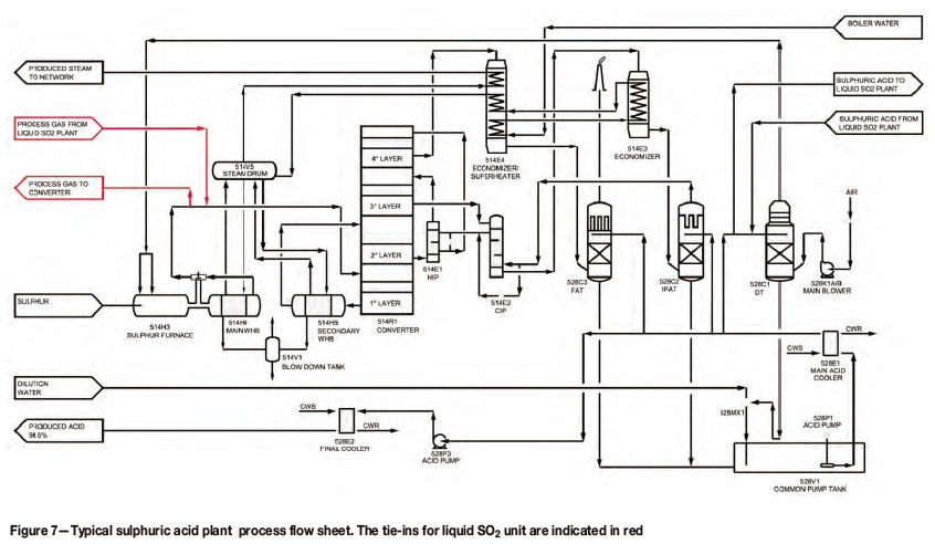
A portion of the SO2 gas leaving the waste heat boiler of the acid plant (see Figure 7) is diverted to the SO2 plant. The gas is cooled in the hot reheat exchanger, preheating the exhaust SO2 gas returning to the acid plant.
The gas is further cooled and cleaned from traces of SO3 inside the SO2 washing tower, to avoid contamination of the liquid SO2 product. Gas sensible heat is removed and SO3 absorbed by countercurrent contact with concentrated acid, circulating through the tower with a dedicated circuit equipped with an acid cooler for temperature control.
A controlled quantity of dilution water is added to the column's tank to maintain the acid concentration at 98.5%. The acid produced by SO3 absorption is delivered to the sulphuric acid plant.
The SO2 gas leaving the top of the tower is boosted by a blower, cooled in the cold reheat exchanger by the return gas, and sent to the SO2 condenser. Inside this unit, part of the SO2 gas is condensed using a refrigerant. Uncondensed SO2 is returned to the acid plant with the exhaust gas, after preheating in the cold and hot reheat exchangers.
The design of the unit has been optimized in order to keep the overall pressure drop of the system below 0.2 bar.
The condensed SO2 is transferred to the liquid storage.
Integration requirements and impact on the sulphuric acid plant performance
The liquid SO2 unit can be considered as a stand-alone package, which can be integrated into either an existing or a new sulphur-burning sulphuric acid plant.
The integration has specific requirements, with a slight impact on the performance of a standard sulphuric acid production plant
The sulphur furnace of the acid plant shall be designed for 12-13 vol.% of SO2 concentration at the outlet. This is feasible using the standard refractory material widely used for sulphur-burning acid plants. The maximum amount of SO2 that can be condensed from this stream (i.e. the total liquid SO2 production capacity) is limited by the SO2/O2 ratio required by the SO2-SO3 converter catalyst.
This ratio shall be within the range of 1.15-1.20, having a residual oxygen content in the stream of about 8-9 vol.%.
The waste heat recovery that can be achieved by an integrated plant is affected by the amount of SO2 removed from the catalytic converter inlet.
An acid plant designed for medium-pressure saturated steam will produce less steam when liquid SO2 is operated. An acid plant designed for medium-pressure superheated steam will produce steam at lower superheating temperature when liquid SO2 is operated. This temperature reduction does not compromise the operation of an electrical power co-generation unit. However, an additional superheater recovering waste heat from the last converter stage could improve the steam superheating temperature, maximizing the efficiency of an eventual power co-generation unit.
As shown in the process flow diagram (Figure 7), the tie-ins between the acid plant and the liquid SO2 unit are limited to very few lines, which are marked in red.
Case study
Desmet Ballestra completed recently a sulphur-burning, sulphuric acid and liquid SO2 project, based on DuPont-MECS technology, for a metal mining complex in the Democratic Republic of Congo.
The key plant parameters are summarized in Table II.
The plant was commissioned in mid-2012 with liquid SO2 production on-stream. Figure 8 shows a photograph of the plant.
© The Southern African Institute of Mining and Metallurgy, 2013. ISSN 2225-6253.
This paper was first presented at the, 4th Sulphur & Sulphuric Acid 2013 Conference, 3-4 April 2013, Sun City, Pilanesberg, South Africa.

