


Services on Demand
Article
 English (pdf)
 Article in xml format
 Article references
Indicators

Related links
-
 Cited by Google
 -
 Similars in Google
Share

 Permalink
Journal of the Southern African Institute of Mining and Metallurgy
On-line version ISSN 2411-9717
Print version ISSN 2225-6253
J. S. Afr. Inst. Min. Metall. vol.113 n.7 Johannesburg Jan. 2013
CONFERENCE PAPERS
DIAMONDS—SOURCE TO USE 2013
Incline caving as a massive mining method
D.D. Munro
WorleyParsonsTWP
ABSTRACT
Finsch Mine is a kimberlite diamond mine located at Lime Acres in the Northern Cape Province of South Africa. The mine was founded in 1961 and started surface mining in 1964. Underground production commenced in 1990 using a modified blast-hole open stoping method for the mining of Blocks 1, 2 and 3. Block 4 is currently being mined as a block cave.
The process of identifying and optimizing a method to mine the Block 5 orebody started in 1991, and in 2006 incline caving was identified as being technically feasible. This paper aims to document the process employed in developing this method by the Block 5 pre-feasibility team as well as discuss the technical challenges encountered during this process.
The paper commences with a history of Finsch Mine and highlights the complex geology and threat of sidewall failure that prompted the decision to use block caving as the mining method for Block 4. A literature study of mines that implemented mining methods upon which the incline cave was conceptualized is then presented. These practices were then used to form the basis for the designs on which the initial geotechnical modelling was done and built upon through an iterative process of modelling and design changes. The ventilation of the mining area, initial productivity simulation results, and the applicability of automation and comminution processes in the incline cave are also presented.
The paper concludes with an investigation into some of the challenges of the mining method, and shows that that incline caving is a technical option available for further investigation in determining the optimal mining method to be employed at Block 5, Finsch Diamond Mine.
Keywords: massive mining, incline caving, geotechnical modelling.
Introduction
The Block 5 conceptual study was started in 1991 with a high-level study and concluded that a block cave mining method would suit the orebody. This study was resumed in 2000 with a confirmation study, and in 2002 a full conceptual team was established. The results of this study indicated that a block cave design should be taken into the pre-feasibility study as the preferred mining method based on net present value (NPV) pending the results of the proposed geotechnical and geological drilling programme.
This proposal was taken to the Finsch Underground Geotechnical Study (FUGS) team, a panel of cave mining experts comprising:
Dr. Alan Guest (Lead)
The proposed mining method was dismissed as being impractical as a result of geotechnical and brow wear concerns, and it was suggested that an 'incline cave' mining concept be investigated. This method has not previously been implemented, and the concept was based on the practices at King Section at Gath's Mine in Zimbabwe and Cassiar Mine in Canada, which used a 'false footwall' mining method with some degree of success.
The incline cave mining method for use at Finsch Diamond Mine was first documented by Paucar and Mthombeni (2004) in a paper presented at MassMinn 2004. This paper aims to discuss the incline cave mining method as proposed for Finsch Block 5 by detailing the findings of modelling and design work.
Finsch Mine was purchased in 2011 by Petra Diamonds, who are currently undertaking further study work.
History of Finsch Diamond Mine
Finsch Diamond Mine is located 160 km west of Kimberley in the Northern Cape Province of South Africa, and first started mining kimberlite in 1964 after the discovery of the pipe in 1960. Mining was started using opencast methods until an elevation of 430 m below surface was reached in September 1990, after which modified blast-hole open stoping (BHOS) was used to mine Blocks 1, 2, and 3 (Preece, 1998). Two shafts were sunk, namely Main Shaft, a 9 m diameter circular shaft which is used for men, material, and ore handling, and Waste Shaft, which initially was used as a ventilation intake for hoisting, but has since been decommissioned and is now used as a ventilation exhaust shaft.
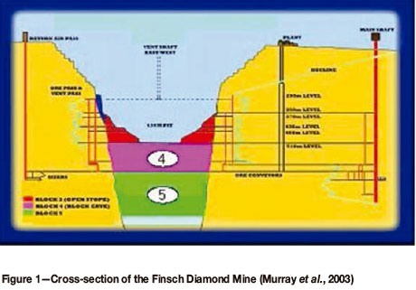
Block caving was selected as the mining method for Finsch Block 4, with the main driver being the risk of sidewall failure in the pit if the BHOS method had been continued, which would have diluted the ore being mined. Block caving has been used in De Beers mines for a number of years at the Kimberly Mines and Cullinan Mine (previously Premier Mine), and has gained favour because of the relatively low operating cost, albeit with a high capital cost associated with the mining method.
Geology
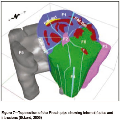
The Finsch kimberlite pipe is located in a host rock of dolomites and limestone overlain with banded ironstone. The kimberlite has been classified into a series of eight different kimberlites, nominated F1 to F8 as depicted in Figure 2.
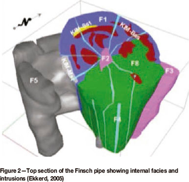
The rock mass ratings (RMRs) of these kimberlites peak in the F8 kimberlites, these being the strongest, and are weakest in the F1 kimberlites. The following two broad zones can be distinguished and are depicted in Figure 3.
1) Southern half of the pipe - predominately F8 - Fair RMR (41 - 60, in brown in Figure 3)
2) Northern half of the pipe - predominately F1 - Poor RMR (21 - 40, in yellow in Figure 3).
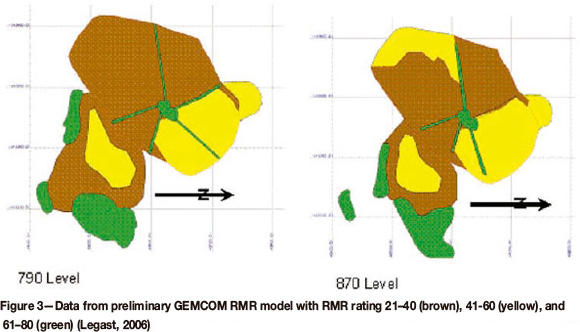
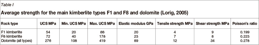
The host rock consists mainly of a series of horizontal layered dolomites and limestones overlain by a banded ironstone formation. From geotechnical drilling the ratings have been calculated as shown in Table I.
Block 4
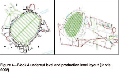
The development of the infrastructure for the Block 4 block cave commenced before 1997, with slot cutting in 2005. Although the tunnel spacing of 30 m on the production level and 15 m on the undercut was slightly greater than has been the case at some of the other mines in the group, a more stringent support regime has been created where high- density roof bolting and cable bolting is the norm. This is complemented by shotcrete, straps, and wire mesh.
Drawpoints are laid out in a single-sided herringbone or Henderson layout with semi-autonomous load haul dump machines (LHDs) planned to load directly into autonomous 50 t dump trucks. These trucks then transport the ore to the gyratory crusher, from where it is transported to the shaft by conveyor and hoisted to surface. These layouts can be seen in Figure 4.
Block 5 conceptual study (Murray et al., 2003)
The Block 5 conceptual study was started in 1991 focusing on the use of a block cave mining method. This study was reinitiated in 2000 by a confirmation study and in 2002 a full conceptual team was established and the study reinitiated (Murray et al., 2003).
The conceptual study team investigated the following three mining methods to determine which was the most applicable to the Finsch Block 5 orebody:
As part of this study, Mr Robin Kear was requested to conduct an economic desktop study and it was from his report that the mining block height and peak production rates were determined (Murray et al., 2003). The main conclusions were as follows:
It was, however, soon realized that the 10 m thick zone containing intensely bedded secondary cryptalgal dolomite with shale layers intersected the country rock just above 880 m level, very close to the minimum level recommended by Mr Kear. This zone was found, through drilling, to be significantly weaker than the rest of the country rock mass and any infrastructure placed in this region would require major support installations.
Above this zone, a previous exploratory drilling programme in the kimberlite had drilled clusters of large-diameter drill-holes (LDD holes). These holes were in the order of 300 mm in diameter and once completed were never backfilled or grouted as a result of the poor ground conditions experienced. Over time these holes have filled with water which has spread to the surrounding kimberlite, resulting in large zones of weathered material. These LDD holes are known to have been stopped around the same elevation at which the shale layer occurs, since this was felt to be the most likely level for the construction of a block cave.
The combination of these two factors has ensured that any cave mining operations have to be conducted below the level of the shale, and therefore no shallower than 888 m Level.
Based on these results, the three proposed mining options were traded off against each other.
The pre-feasibility block cave
Subsequent to the October 2004 FUGS meeting the pre-feasibility study team initiated the design of an incline cave based on the recommendations of the above meeting (Lorig, 2004). Soon after, however, the scope of the project was set such that the project team did not abandon the block cave mining method and an instruction was given that two variations of the block cave concept were to be designed in parallel with that of the incline cave.
Geotechnical investigations
The number of levels in an incline cave is in direct proportion to the interactive draw zone (IDZ), tunnel spacing, and footprint area of the orebody to be mined. This is best explained as follows:
According to the IDZ theory at the time, the draw cones of adjacent drawpoints should be positioned such that they interact so as to promote interactive draw, with the spacing of these drawpoints being determined by two dimensions, namely tunnel spacing and level spacing.
Tunnel and level spacing
Two different layouts can be created for the same orebody, namely a physically strong layout, which relies on geotechnical considerations, and secondly a layout that focuses on the ideal spacing of drawpoints so as to achieve interactive draw. As can be expected these two objectives are not complementary, and layouts are designed with a lower overall strength so as to obtain better draw or vice versa. It is seldom possible to create a balance between the two.
In the Finsch Block 5 design it was realized at an early stage in the project that the orebody being considered for Block 5 would be subjected to larger stresses than had been experienced in Block 4, mainly because of the depth of mining. Itasca had therefore been commissioned to perform modelling throughout the pre-feasibility stage of the project using both FLAC3D and FLAC2D.
The block model was created from drilling data in GEMCOM and included the mined-out pit and all subsequent mining including Blocks 1, 2, 3, and 4, resulting in the mine scale model shown in Figure 5.
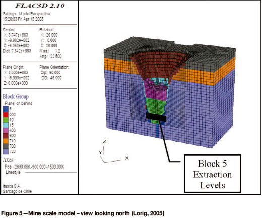
ITASCA modelling (Lorig, 2005)
The first modelling was aimed at determining the need for an overcut in the incline cave layout. Two models were run with results indicating that although only a small benefit was achieved, an overcut did reduce the stress on subsequent levels and that an undercut would be essential to ensure caving until at least four levels were in production.
ITASCA modelling (Lorig, 2006a)
The February 2006 modelling aimed to investigate the effects of mining activities on the mining block and determine which of the two proposed layouts, namely the block cave and the incline cave, presented the more competent layout. To do this both the incline cave and block mining layouts were modelled in increments of 6 months, showing the progression of the development and then the undercutting of the orebody. The GEMCOM block model was again used but enhanced to show the facies differences. From these results of the rock mass strength/stress analysis the following was concluded:
Overall, although the differences were small, the inclined layout showed an advantage over the block cave.
Uncaved remnants
A further concern was that remnants remaining unbroken in the incline cave would form arches across the orebody. This was also modelled and found to not be a risk, as shown in Figure 6.
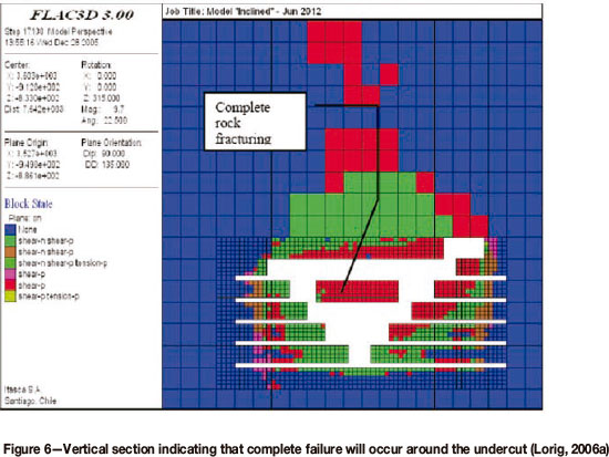
The comparison of the two mining methods showed little evidence that one method was superior to the other, yet the differences did favour the incline cave layout, with 'serious instabilities' being identified in the contact zone around the pipe and in areas of lower RMR (RMR<40) and uniaxial compressive strength (UCS<55), where careful support designs would be needed (Lorig, 2006a).
Conclusions of the February 2006 report
From the information provided it was recommended that the following be considered to increase the strength of the incline cave layout:
General layouts
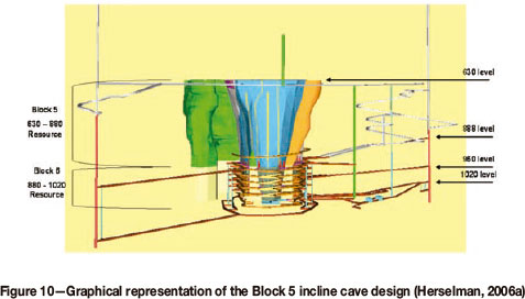
In the Finsch Block 5 incline cave layouts, the orebody would be exploited from below the shale layer with the first full level being located on 888 Level. From this point initial designs have levels spaced at 18 m intervals. Unlike other mining methods where the number of levels is predetermined based on production requirements, the incline cave relies on the spacing of tunnels and orientation of the tunnels on different levels relative to each other to determine the number of levels. These principles would now be discussed.
Vertical alignment
It was decided early on in the project that tunnels on successive levels should be stacked as opposed to being arranged in a staggered layout, so that a stronger layout would be formed with a single, continuous pillar being formed between the columns of successive tunnels. Had the tunnels been staggered, as is the practice on modern SLCs (Bull and Page, 2000) and the Koffiefontein Front Cave (Rabe and Hannweg, 2003), the constraining forces would have been less. The support required to ensure the stability of the brow would also have been increased.
Tunnel orientation
The Finsch pipe has been found to be slightly elliptical (Legast, 2006) with the long axis lying on an east to west plane as can be seen in Figure 7, with a precursor of hypabyssal kimberlitic material that is more competent than the rest of the orebody extending to the south. This precursor is not planned to be mined as part of the Block 5 incline cave and it was preferred to locate all infrastructure and as many tunnels as possible out of this zone.
The resulting decision was that tunnel orientation would be north/south orientation and would ensure that the distance that an LHD would need to travel within the pipe would be minimized. Most of the internal dykes would also be intersected perpendicularly, reducing the risk of tunnel collapse in these areas.
Tunnel dimensions and spacings
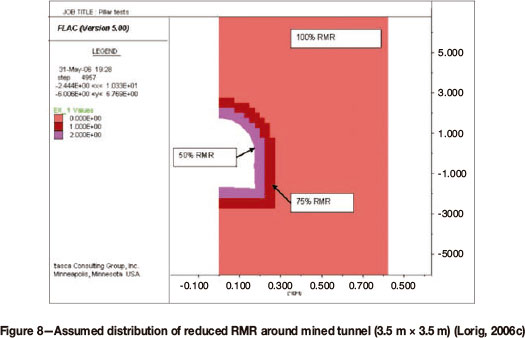
RMR does not account for the effects of blast-induced damage, while MRMR does through the application of an appropriate factor that varies between 80% for poor blasting to 100% for boring operations. In the application by ITASCA, the 0.5 m zone immediately surrounding the tunnel was reduced by 50%, far more than the MRMR factor, while the subsequent 0.5 m zone was reduced by 25% of the original RMR.
Support
The primary support in kimberlite tunnels would begin with the controlled blasting of the rock to minimize overbreak. Thereafter a layer sealant would be applied to reduce the effects of weathering as the virgin ground is subjected to atmospheric conditions. Shotcrete would be applied through which grouted roofbolts of 3.0 m length would be installed at 0.7 m spacing. In the ITASCA modelling of June 2006 (Lorig, 2006c) it had been found that roofbolts would also be required in some areas in the footwall to minimize footwall heave.
The primary support is then followed by cable anchors (which are intended to stitch the pillars together), wire mesh and vibro mesh as an aerial support medium, and tendon cable straps. A final layer of shotcrete would then be applied over this installation At drawpoints and dolomite/kimberlite contacts it is anticipated that stiffer support in the form of steel arches would be required. This methodology has been used at Finsch and Cullinan in the past with good success rates.
Production layouts
The diagrams in Figure 9 represent plan views of all levels from 870 Level to 960 Level. As can be seen, an undercut level has been designed on 888 Level with the aim of reducing stress for all subsequent production levels. On 924 Level another undercut is done, the mid-cut, which is used to de-stress the levels below these. The method to be employed and scheduling of the undercut is discussed under the following paragraphs.
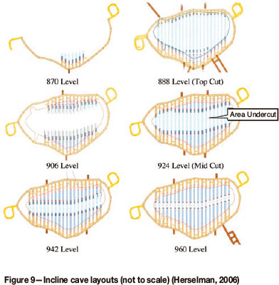
The design of the above layouts was achieved by commencing the design on the bottom-most level, situating drawpoints in the middle of the orebody. The troughs on subsequent levels were then placed so that they interacted with the lower drawpoints, ensuring an equal coverage of the entire orebody. Once the uppermost levels were reached, any remaining footprint that had not been assigned coverage had a drawpoint associated.
Undercutting methodology The need for an undercut(s)
The effects of the inclusion of an undercut were modelled in terms of rock mass strength/stress diagrams (Lorig, 2005). The large zones of reduced stress indicate that less intensive support systems would be required up to the fourth production level, after which the benefit gained is no longer significant and a second undercut or 'mid-cut' would need to be included in the design (Lorig, 2005).
Direction of undercut
Block 4 would be undermined through the undercutting of Block 5 and as such mining in the same direction would be adventitious and allow the lag between the two blocks to be unconstrained.
Shape of the undercut
A flat undercut design, moving from F8 to F1, was considered more practical for the following reasons:
When considering the chevron undercut the following can be seen:
Infrastructure Development
Finsch mine is currently exploiting the Block 4 orebody, which is located above Block 5 with production at the time expected to start decreasing in 2011 (Finsch Mine, 2006). With only one hoisting facility currently installed on the mine, Waste Shaft was earmarked to be re-equipped to serve as a primary waste handling facility for Block 5. Waste Shaft was originally installed to handle waste from underground operations, and was decommissioned and is currently used as only a return airway. The new loading station would be constructed on 888 Level with tips into which 20 t dump trucks can discharge development waste rock.
Main Shaft would be deepened and the hoisting speed increased to allow it to hoist 5.4 Mt/a. During the deepening, a spare compartment in the shaft would be equipped with a 7 t skip and winding arrangements, which would allow waste from shaft deepening and development to be hoisted to surface. During shaft deepening a sub-shaft assembly would be installed that would hoist waste from the lowest level of the mine on 1020 Level using a kibble on a multi-drum winder to the existing 65 Level.. This would then empty the ore into a 70°, 5 m diameter pass that would feed into a loading flask and ultimately the 7 t skip. On completion of Main Shaft deepening and equipping this 7 t skip could be decommissioned, although the availability might prove useful in later expansion projects.
Steady state
In the Finsch Block 5 pre-feasibility incline cave layout, diesel LHDs would tip into tips that would be equipped with a rock breaker and link into a 6 m diameter orepass located on either side of the pipe. These would each be equipped with a hydrostroke feeder on the haulage level and would feed into 50 t dump trucks. The ore would then be transported to the tip in one of the two tramming loops. The simultaneous tipping of three trucks would be incorporated into the design of the tip before the ore is fed into the crushing assembly.
The choice of comminution method would be decided in the feasibility study phase of the project, with the following three options in contention:
From the crusher the -300 mm ore would be transported on a conveyor belt to the Main Shaft loading box and hoisted to surface.
Ventilation
All tunnels in the incline cave layout would form 'dead ends' on all levels at some stage in their lives, with the top and mid-cuts starting off as holed tunnels before they are undercut and ending up as 'dead ends'. These would need to be ventilated with an exhaust system using ventilation ducting, with two tunnels being serviced by a single raise-bored ventilation hole leading to the ventilation and water handling level. Such a system would be expensive in terms of capital and operating costs.
The capital costs are affected mainly by the cost of purchasing all the required ventilation ducting and fans, with the running costs being driven mainly by the cost of running fans in every tunnel. Two possibilities exist to control this cost, the first being to reduce the number of fans by placing larger fans after the point where the two ventilation ducts join, and secondly using a ventilation on demand (VoD) system to control the amount of time the fans stay on.
At its most complex this system would sense the presence of an employee or machine and turn on the fan, turning off when the person or machine exits the area.
Communition and secondary breaking
In the incline cave layout, primary fragmentation would occur as a result of longhole drill and blasting at the troughs and undercut. This would, as discussed earlier, be initiated by creating the free-breaking face by raise-boring a hole beyond the top of the undercut into which subsequent rings would be blasted. The swell would be loaded off between these blasts with an LHD. Little oversize material is expected from this as rings would be designed in such a manner that rocks larger than can be handled by an LHD would not be produced. Secondary breaking is required for rocks larger than can be safely loaded by an LHD from a drawpoint and transported to the tip.
Areas of concern
Air blast potential
Following the experiences at North Parkes (Hebblewhite, 2002), a lot of emphasis has been placed on the possibility of air blasts in new cave designs. In the incline cave the same concerns over air blasts would be valid as with conventional block caves, with the same principles being used to address the concerns, namely the cushion of ore left in the drawpoints, adequate monitoring of the cave back, and proper draw control.
As with any caving operation there is the possibility of mud pushes and mud rushes occurring. Where the incline cave is more beneficial over methods such as SLCs and front caves is that because of the number of levels and footprint over which these occur, the ingress of water can be diverted between a number of drawpoints, in much the same way that water is handled in block caves through preferential draw of selected drawpoints (Laubscher, 2000).
Conclusions
Incline caving, although as yet not proven through implemen- tation, has been found in this pre-feasibility study to be technically feasible as a mining method that can be employed in the mining of Block 5 at Finsch Mine. This was done through the appropriate use of technology, in the form of geotechnical modelling and the involvement of industry experts in the form of the FUGS team.
This paper has detailed the major advantages that the incline cave has as a mining method in kimberlite orebodies, these being:
There are a number of factors which need further investigation in a subsequent phase of the project. These include optimizing tunnel dimensions and the resulting support regimes, and modelling the stresses induced on the orebody through various orientations of the undercut. The results of these studies would conclude the technical feasibility study into the use of the incline cave mining method for use at Block 5, Finsch Mine.
Acknowledgments
The author would like to thank the management and staff at De Beers Consolidated Mines for permission to present this paper, which was written while in their employ. In particular the work of the Geotechnical Department, including Dr. Alan Guest, Dave Wilson, and Pierre Legast at DBCM, in developing the concept with the Block 5 team needs to be acknowledged, as well as the assistance of the team in compiling this paper. In addition, the management of Petra Diamonds are thanked for their permission to publish this paper after their acquisition of the Finsch Diamond Mine. This paper was originally presented to the University of the Witwatersrand, Johannesburg as part of the Masters in Engineering programme under the mentorship of Professor Dick Stacey, and he is thanked for his assistance.
References
Anonymous. 2003. Koffiefontein rock mass failure, geotechnical update presentation. De Beers Consolidated Mines - Koffiefontein Mine. [ Links ]
Brown, E.T. 2003. Block Cave Geomechanics. JKMRC Monograph Series In Mining And Mineral Processing, Queensland, Australia. [ Links ]
Bieniawski, Z.T. 1973. Engineering classification of jointed rock masses. Transactions of the South African Institution of Civil Engineering, vol. 15, no. 12. pp. 353-343. [ Links ]
Bull, G. and Page, C.H. 2000. Sub level caving, today's dependable low cost ore factory. Massmin 2000, Brisbane, Queensland, 29 October-2 November 2000. pp. 537-556. [ Links ]
Carew, T.J. 1992. Footwall-drawpoint caving At Cassiar Mine. Massmin 92, Johannesburg. Glen, H.W. (ed.). South African Institute of Mining and Metallurgy. pp. 295-301. [ Links ]
De Kock, H. 1992. Gath's Asbestos Mine. Chamber of Mines Journal, June 1992. pp. 15-21. [ Links ]
Ekkerd, J. 2005. Note for the record: the geology of Block 5. De Beers Finsch Mine. [ Links ]
Finsch Mine. 2006. Finsch Mine strategic business plan. Finsch Diamond Mine. [ Links ]
Herselman, H. 2006a. Presentation: Steercom Presentation 16. [ Links ]
Herselman, H. 2006b. Presentation: Undercut Philosophies. [ Links ]
Hebblewhite, B.K. 2002. Final report on DMR investigation for coronial inquest North Parkes Mine collapse. Volume 1. Unisearch Ltd, Sydney, New South wales. J055066. [ Links ]
Heslop T.G. 1973. Internal company report. [ Links ]
HULL, R. 2006. Presentation: PCBC Modelling results. [ Links ]
Jakubec, J., Lorig, L., Atkinsone, L., and Laubscher, D. 2004. Memorandum: site visit notes - Finsch Block 5 Project. [ Links ]
Jarvis, M. 2002. Presentation: Finsch Mine block cave project - 7 June 2002. [ Links ]
Laubscher, D. 1975. Class distinction in rock masses. Coal, Gold, and Base Minerals of South Africa, 23 Aug. 1975 (as cited in Laubscher, 2000). [ Links ]
Laubscher, D.A. 1990. Geomechanics classification system for the rating of rock mass in mine design. Journal of the South African Institute of Mining and Metallurgy, vol. 90, no 10. October 1990. pp 257-273 (as cited in Laubscher, 2000). [ Links ]
Laubscher, D.A. 2000. A Practical Guide Manual on Block Caving, International Caving Study (1997-2000). [ Links ]
Laubscher, D.A. 2003. Cave Mining Handbook. De Beers, Johannesburg. [ Links ]
Laubscher, D.A. and Taylor, H.W. 1976. The importance of geomechanics classification of jointed rock masses in mining operations. Proceedings of the Symposium on Exploration for Rock Engineering, Johannesburg, November 1976 (as cited in Laubscher, 2000). [ Links ]
Legast, P. 2006. Finsch Block 5 pre-feasibility geotechnical investigation. Johannesburg, South Africa. [ Links ]
Lorig, L. 2005. Geotechnical modelling for Block 5 at Finsch Mine, April 2005. [ Links ]
Lorig, L. 2006a. Geotechnical modelling for Block 5 at Finsch Mine, February 2006. [ Links ]
Lorig, L. 2006b. Calibration of stress and rock mass conditions at AUC (Cullinan Mine) and Block 4 (Finsch Mine), May 2006. [ Links ]
Lorig, L. Memorandum: preliminary evaluation of Finsch Block 5 - undercut level tunnel design. [ Links ]
Lorig, L. 2006c. Geotechnical modelling for Block 5 at Finsch Mine, June 2006. [ Links ]
Marsden, H. 2004. Presentation: AUC Project, Quarterly Project Review, September 2004. Wits Block Cave School 2004. University of the Witwatersrand, Johannesburg. [ Links ]
Morrell, W. 2004. Presentation: Cullinan Diamond Mine overview. [ Links ]
Murray, J. Richter, B., Mthombeni, C., and Kpekpena, P. 2003. Finsch Block 5 pre-feasibility study update report. De Beers, Johannesburg. [ Links ]
Mthombeni, C. and Paucar, C. 2004. Incline cave: a technical alternative to method to mine kimberlite deposits at depth. Massmin 2004, Santiago, Chile, March 2004. pp 91-95. [ Links ]
Panaou, C. 2006. Simulation of the incline cave mining method report, version 4. Anglo Technical Division, Johannesburg. [ Links ]
Preece, C. 1998. Finsch Mine: open pit to open stoping to block caving. Underground Mining Methods. SME, 2001. pp. 439-453. [ Links ]
Priest, M. and Hawley, D. Undated. Front caving, A solution to waste dilution at Koffiefontein Mine for the extraction of the 370 m to 490 m ore reserve. [ Links ]
Rabe, J. and Hannweg, L. 2003. Presentation: Koffiefontein Mine rockmass failure, geotechnical update. [ Links ]
Seopa, H. 2006. Note for the record: flat cave pre feasibility document. De Beers Group Services, Johannesburg. [ Links ]
Van Hout, G., Allen, S., Breed, M., and Singelton, M. Status of draw control practice and waste management at Cullinan Diamond Mine. Massmin 2004. Santiago, Chile. pp. 491-497. [ Links ]
Wilson, A.D. and Talu, M.S. 2004. A review of the support systems being applied to the Block 4 cave project of De Beers Finsch Mine, South Africa. Massmin 2004, Santiago, Chile. [ Links ]
Talu, M.S. and Wilson, A.D. 2004. Innovative mining method and related support systems and quality assurance for a large underground crusher excavation. Massmin 2004, Santiago, Chile. [ Links ]
Wilson, A.D., Talu, M.S., and Henshall, R.B.H. 2005. Presentation: Finsch Mine tunnel profiler; Block 4 - block cave project. Best Practices in Rock Engineering. 3rd Southern African Rock Engineering Symposium, Randburg, South Africa. [ Links ]
Morton, K.L., Preece, C.A., Beaton, R., Twiggs, C.J., and Wilson, A.D. 2007. Block cave dewatering: a case history from De Beers Finsch Diamond Mine, Northern Cape, South Africa. 1st International Symposium on Block and Sub-Level Caving, Cave Mining, Cape Town, South Africa. Southern African Institute of Mining and Metallurgy, Johannesburg. pp. 239-264. [ Links ]
Wilson, A.D. 2008. Effectiveness of support system employed in the Finsch Mine Block 4 cave. 6th international Symposium on Ground Support in Mining and Civil Engineering Construction, Cape Town, South Africa. Southern African Institute of Mining and Metallurgy, Johannesburg. pp. 489-502 [ Links ]
Whewell, B.W. and Pautz, P.N. 1986. False footwall drawpoint system as adopted by King Section, Gath's Mine. Chamber of Mines Journal. pp. 21-28. [ Links ]
Wilson, A.D. 2008. Presentation: Managing changes to support systems during project implementation. Mining Review Africa; Safety in Deep Mining. Johannesburg, South Africa, July 2008. [ Links ]
© The Southern African Institute of Mining and Metallurgy, 2013. ISSN 2225-6253.
This paper was first presented at the, Diamonds-Source to Use 2013 Conference, 12-13 March 2013, Misty Hills Country Hotel and Conference Centre, Cradle of Humankind, Muldersdrift, South Africa.

