


Serviços Personalizados
Artigo
 Inglês (pdf)
 Artigo em XML
 Referências do artigo
Indicadores

Links relacionados
-
 Citado por Google
 -
 Similares em Google
Compartilhar

 Permalink
Journal of the Southern African Institute of Mining and Metallurgy
versão On-line ISSN 2411-9717
versão impressa ISSN 2225-6253
J. S. Afr. Inst. Min. Metall. vol.113 no.6 Johannesburg Jun. 2013
Location of seismic events at Kusasalethu mine using a layered velocity model
D.B. Rebuli
Institute of Mine Seismology
SYNOPSIS
Seismic networks in deep gold mines of South Africa are often planar owing to the tabular geometry of the orebody and, therefore, the mining infrastructure. Consequently, seismic event locations are poorly constrained in the direction perpendicular to the reef plane, and symmetrical locations above and below the reef plane may fit the observed data equally well. This problem may be resolved in situations where the strata above and below the reef plane have significantly different seismic velocities, which is the case for the Ventersdorp Contact Reef at Kusasalethu mine (previously Elandskraal, the amalgamation of Deelkraal and Elandsrand). A location method using a layered location model that takes into account the velocity contrast between the layers was tested. Observed direct- and head-waves were used to determine the velocity bounds of the P-wave velocities in the two-layer model. The data-set was also used to find the best P- and S-wave velocities for the two layers by grid searching over a range of velocities and minimizing the sum of the travel-time residuals. The results from the grid search and those from the calibration of velocities using direct- and head-waves give similar P-wave velocities for each of the two layers. A second set of seismic events was then relocated with this layered model and locations closer to reef were found. This simple layered location method goes some way to reduce the reef-perpendicular location errors for Kusasalethu mine in particular.
Keywords: mine seismology, velocity model, location methods.
Introduction
Most seismological analysis techniques rely on the spatial distribution of seismic events and therefore reliable locations are very important (Mendecki, 1997; Mikula, 2005; McGarr, 1984; Glazer and Hepworth, 2005; Basson and Ras, 2005; Alexander and Trifu, 2005; Essrich, 2005). Locating a seismic event recorded by sensors in a seismic network becomes an optimization problem (Mendecki and Sciocatti, 1997) where the optimum event location and origin time is searched for by minimizing the difference between observed and calculated P- and S-wave arrival times. A 4D minimization function F - also called the travel-time residual - is constructed for each seismic event recorded by N sensors:
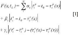
where x is the source location vector in 3D space, t0 is the origin time, tip is the P-wave arrival time at the ith sensor, tip is the calculated P-wave travel time from the source location to the ith sensor, etc. αi is unity for seismograms with accurate common time and clear P-wave arrivals, and zero otherwise. βi is unity for seismograms with accurate common time and clear S-wave arrivals, and zero otherwise.γi is unity for seismograms without accurate common time and with clear P- and S-wave arrivals, and zero otherwise (Sewjee, Lynch, and du Toit, 2008).
Traditionally, straight rays through a homogenous velocity model are assumed and travel times are simply calculated by dividing the Euclidean distance from source to sensor by the P- or S-wave velocity. This approximation works well in the presence of small changes in the seismic wave velocities across a network.
Kusasalethu mine setting
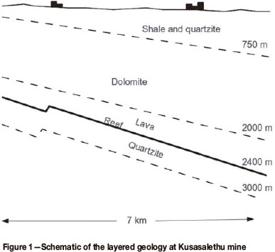
Kusasalethu mine is the westernmost actively producing mine in the West Wits Line, the goldfield west of Johannesburg. Mining is focused on the Ventersdorp Contact Reef which is a conglomerate reef band with a strike of 65° and a dip of 23° to the south. The hangingwall is Ventersdorp Lava with a UCS of around 300 MPa. The footwall is competent quartzite with a UCS of between 180-250MPa, extending between 430-550 m below reef (Figure 1).
Straight-ray location model
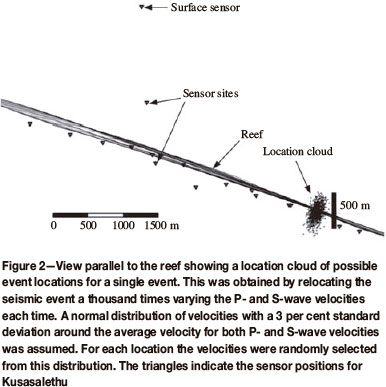
Because of the thin fairly planar reef at Kusasalethu, with access generally confined around this reef, the seismic sensor array is planar. Numerical simulations show large location errors in the direction perpendicular to the reef if only small errors in the seismic wave velocities are introduced (Figure 2). A number of sources for velocity calibration have been used at Kusasalethu over the past couple of years, ranging from production blasts to damaging seismic events, but as shown from Figure 2, small velocity errors can still give poor locations perpendicular to reef as the problem is fundamentally a geometric one.
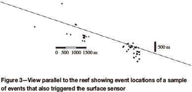
To mitigate against the reef-perpendicular location uncertainty, sensors are usually placed on surface to aid with 3D coverage. These sensors tend to be triggered only by larger events due to the distance from the sources. The average velocities for the surface sensors also tend to depend on where the source is. (Different ray paths to surface sensors may mean one average velocity is not appropriate for large mines.) For this location technique the effectiveness of surface sensors in constraining the locations tends to be limited (Figure 3).
Planar location model
A simple method of overcoming the location accuracy problem posed by planar seismic arrays is to confine the calculated locations to a plane parallel to the reef by restricting the solutions to the plane. Since most mining-induced seismicity occurs close to reef, the loss of accuracy in the direction perpendicular to the reef tends to be missed only for structure-related events. For events originating significantly off-reef, the projection of the location onto this plane can give misleading locations. It may be possible to have a hybrid model, where face-related events are located with this planar model while larger events (possibly structure-related) use the straight-ray model, but this still means large uncertainties in location for the larger events. This also means small events associated with structures may be mislocated on the reef plane. Another negative effect of constraining these locations to a plane is that moment tensor estimates based on direction of first motion should also be limited to directions within the plane to prevent poor estimates.
The layered nature of Kusasalethu gold mine may help in breaking the travel time symmetry (equally probable solutions above and below the reef), especially if the layers have a strong enough velocity contrast. This layered model is another method for locating seismic events and is discussed below.
Ray tracing location models have been shown to improve location accuracies on mines with planar arrays (Sewjee, Lynch, and du Toit, 2008; Webber, 1988). Unfortunately, ray tracing requires a large velocity model that scales with the number of sensors in the array and is memory intensive. This may not be ideal for routine data processing where a simpler model would be preferred.
Layered location model
The velocity structure for Kusasalethu mine can be inferred from Figure 1. This structure can be viewed as a simple two-layered model (near reef) with a different set of velocities for the upper (lava) and lower (quartzite) layers. We are concerned only with the layers close to reef, as this is where most of the seismicity is expected. The different travel times through these layers may help to break the symmetry in the travel times for paths above and below reef, created by the planar seismic array, enough to improve the 3D location accuracy. In most instances the ray paths are simple. It is only the case of the head-wave ray path (described below) that the Eikonal equation is higher order. Solving the Eikonal equation numerically with bisection for this case is possible, allowing for fast computation. Differential evolution (Storn and Price, 1995) or Simplex methods (Nelder and Mead, 1965) of minimization of the cost function are then practical.
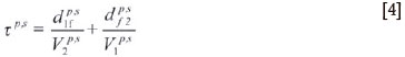
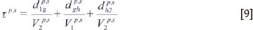
In theory this means that the τips values in Equation [1] are modified depending on the fastest ray paths as follows:
For the ray path to sensor A in Figure 4, τips is unchanged as the fastest path remains in one layer.
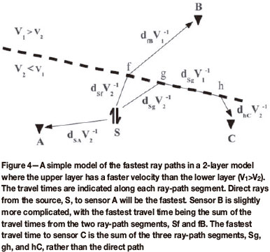
For the ray path to sensor B in Figure 4, the optimal inflection point, f, needs to be found:

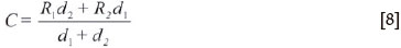
where R is the projection of point on the interface plane, where 1 is the tested source location and 2 the sensor location.

where Vi, is the velocity of layer i, di is the orthogonal distance from point i to the interface (see dsf and dfB in Figure 4 for example), D is the distance between points 1 and 2 projected onto the interface, and l is a number between 0 and 1 which gives the best inflection point f. Then the P and S wave travel times in Equation [1] become
For the ray path to sensor C in Figure 4 two points on the interface need to be found, namely g and h.

and

where
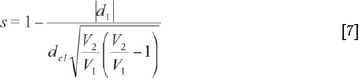
with ácl the distance between Rl and C, the mid-way point on the interface between points 1 and 2 .
Then the P and S wave travel times in Equation [1] become
It is worth noting that the points f, g, and h may differ for the P- and S- waves.
Finally the travel-time residual, F, is minimized to find the best event location.
The task of defining the layered model becomes one of setting where the interface between the two layers is and the velocities associated with each layer. However, the reef should be a reasonable first estimate of the former unknown. For the latter unknowns, head-waves observed in recorded seismograms from most sites were useful.
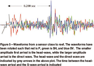
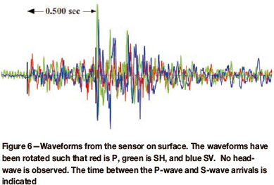
Head-waves are the result of seismic waves travelling from a slower medium to a faster medium. Part of the wave travels along this velocity interface at the faster velocity, radiating reflected waves (Huygen's principle) of lower amplitude back into the slower layer (see Cerveny and Ravindra, 1971 for a detailed study of head-waves) (Figure 4). Sensors in the slower layer then record a smaller amplitude arrival before the direct arrival (Figure 5). In contrast, head-waves will not be present for sensors in the fast layer as the direct ray path will be the fastest path (Figure 6). The apparent velocity of the head-wave then gives information about the velocity of the faster layer. This is not a direct measure of the faster velocities but rather an average based on the travel times through the slow medium and along the interface. Ideally, calibration blasts in each layer could be used to estimate the fast and slow velocities and where the interface lies, but since access off-reef is limited these may not be possible. In the absence of such blasts, a different method was used here.
Calibrating the layered location model
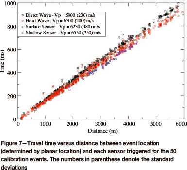
A selection of 50 events from the mine was processed using the direct arrivals. These were then located using the planar location method mentioned above. The arrival times of the P-wave head-waves were determined for those sites where head-waves were found. Using the origin times and locations found from the planar locations, the travel times to each sensor for the direct P-wave and (where observed) head-wave were plotted against the distance between the sensors and the planar locations (Figure 7). A least-squares fit for different sensors (those with observed head-waves and those without) gives average P-wave velocities for the different paths.
The estimated P-wave velocity from the head-waves gives a lower bound to the velocity of the fast layer as these waves have ray paths that do travel through the lower (slow) layer for at least a short distance.
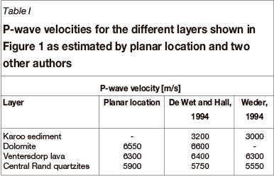
Kusasalethu does have a sensor above reef and a sensor on surface (Figure 2). Only direct arrivals were observed at these sensors, indicating the interface (the plane separating the two layers) must be below the shallow sensor. If we assume the interface is close to the reef, as implied by the geology, the velocity calibrations from the planar located events for the shallower and surface sensor then gives a reasonable estimate of the P-wave velocity in the faster layer (Snell's law would give the ray path for waves travelling from the slower medium into the faster medium, with the travel times in each layer determining the averaged velocities observed). The sensor on surface does show a lower average P-wave velocity compared with the shallow sensor, but this can be explained by the geology, where a second layer with a lower velocity is present closer to surface. These velocities are in line with results from other authors, as indicated by Table I.
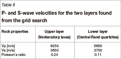
Unfortunately, the head-waves from the S-waves are mixed in with the coda from the P-waves, making it difficult to estimate the S-wave velocity in the fast layer. To get around this problem, the height of the interface was assumed just above reef. P-wave velocities around those estimated from the direct and head-waves (Figure 6) were grid-searched for the velocity that gave the lowest sum of travel time residuals for the sample of 50 events. The S-wave velocities were also grid-searched at the same time around the average S-wave velocity found from the planar located events. The grid search gave velocities as indicated in Table II. These give Poisson ratios for the quartzite of 0.11 (compared with 0.17 (Gercek, 2007)) and 0.24 for lava (compared with 0.24-0.29 (Christensen, 1996)).
Results
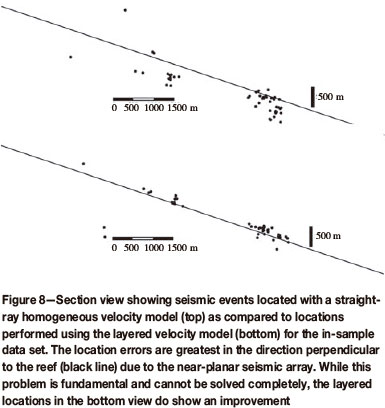
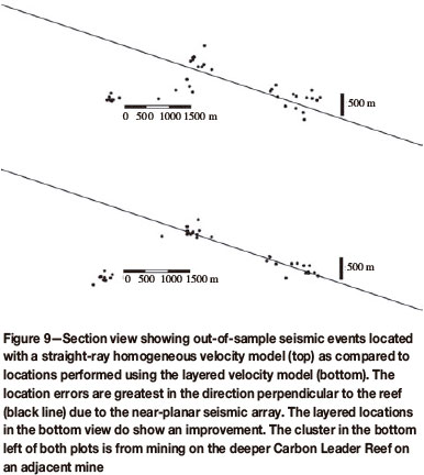
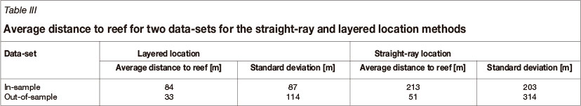
The velocities from Table II were used to relocate the test sample of 50 events using the layered location method. A comparison of the locations relative to reef for the straight-ray method (see section on the straight-ray location model) and the layered location method are shown in Figure 8. A second selection of events, not used in the velocity calibration, was picked for the direct arrivals, making use of the fast head-waves when present. This selection was relocated using straight-rays and the layered location method as an out-of-sample test. The comparison of the locations relative to reef for these out-of-sample events is shown in Figure 9, with Table III showing the average distance to reef for the in- and out-of-sample data sets for the different location methods.
Conclusion
Using the layered nature of the geology at Kusasalethu mine, the travel time symmetry above and below reef caused by the planar seismic array can be broken to some extent. A layered location model taking into account the velocity contrast between the layers close to reef was designed. A data-set of direct- and head-wave arrivals was used to determine the P-wave velocities of the two layers with the reef taken as the plane of intersection of the two contrasting layers. This dataset was also used to find the best P- and S-wave velocities for the two layers by grid-searching over a range of velocities and minimizing the sum of the location errors. The results from the grid search and those from the calibration of velocities using direct- and head-waves give similar P-wave velocities for the two layers.
A second set of seismic events was relocated with this model as an out-of-sample verification and locations closer to reef were found. This simple layered location method does improve the fundamental problem of a planar seismic network for Kusasalethu mine in particular. The geometric problem of a planar seismic array is not removed, but the effect is reduced by the break in the symmetry for rays above and below reef.
This is a simple location method that is easy to perform on a routine basis compared with a ray-tracing method, which requires significant calibration and is generally resource-intensive.
References
Alexander, J. and Trifu, C. 2005. Monitoring mine seismicity in Canada. Proceedings of the Sixth International Symposium on Rockbursts and Seismicity in Mines, Perth, Western Australia, 9-11 March 2005. Potvin, Y. and Hudyma, M. (eds.). Australian Centre for Geomechanics. pp. 352-358. [ Links ]
Basson, F.R.P. and Ras, D.J.R.M. 2005. A method to examine the time-space relationship between seismic events. Proceedings of the Sixth International Symposium on Rockbursts and Seismicity in Mines, Perth, Western Australia, 9-11 March 2005 Potvin, Y. and Hudyma, M. (eds.). Australian Centrefor Geomechanics. pp. 347-351. [ Links ]
Cerveny, V. and Ravindra, R. 1971. Theory of Seismic Head Waves. University of Toronto Press. [ Links ]
Christensen, N. I. 1996. Poisson's ratio and crustal seismology. Journal of Geophysical Research, vol. 101 (B2). pp. 3139-3156. [ Links ]
De Wet, J.A.J. and Hall, D.A. 1994. Interpretation of the Oryx 3-D seismic survey. Proceedings XVth CMMI Congress. Anhaeusser, C.R. (ed.). Symposium Series S14, 3. South African Institute of Mining and Metallurgy, Johannesburg. pp. 259-270. [ Links ]
Essrich, F. 2005. Mine Seismology for rock engineers- an outline of required competencies. Proceedings of the Sixth International Symposium on Rockbursts and Seismicity in Mines, Perth, Western Australia, 9-11 March 2005 Potvin, Y. and Hudyma, M. (eds.). Australian Centre for Geomechanics. pp. 359-364. [ Links ]
Gercek, H. 2007. Poisson's ratio values for rocks. International Journal of Rock Mechanics and Mining Sciences, vol. 44, no. 1. pp. 1-13. [ Links ]
Glazer, S.N. and Hepworth, N. 2005. Seismicity induced by cave mining, Palabora experience. Proceedings of the Sixth International Symposium on Rockbursts and Seismicity in Mines, Perth, Western Australia, 9-11 March 2005. Potvin, Y. and Hudyma, M. (eds.). Australian Centre for Geomechanics. pp. 280-289. [ Links ]
McGarr, A. 1984. Some applications of seismic source mechanism studies to assessing underground hazard. Proceedings of the First International Congress on Rockbursts and Seismicity in Mines, Johannesburg, South Africa. Gay, N.C. and Wainwright, E.H. (eds.). Symposium series S6. South African Institute of Mining and Metallurgy. pp. 199-208. [ Links ]
Mendecki, A.J. 1997. Seismic Monitoring in Mines. Mendecki, A.J. (ed.). Chapman and Hall, London. [ Links ]
Mendecki, A.J. and Sciocatti, M. 1997. Seismic Monitoring in Mines. Mendecki, A.J. (ed.). Chapman and Hall, London. pp. 87-107 [ Links ]
Mikula, P.A. 2005. The practice of seismic management in mines - how to love your seismic monitoring system. Proceedings of the Sixth International Symposium on Rockbursts and Seismicity in Mines, Perth, Western
Australia, 9-11 March 2005. Potvin, Y. and Hudyma, M. (eds.). Australian Centre for Geomechanics. pp. 21-31.
Nelder, J.A. and Mead, R.A. 1965. Simplex method for function minimization. Computer Journal, vol. 7. pp. 308-313. [ Links ]
Sewjee, R., Lynch, R., and du Toit, C. 2008. Locating seismic events in mines containing strongly heterogeneous media. MassMin 2008. Proceedings of the Fifth International Conference and Exhibition on Mass Mining, Lulea, Sweden. Schunnesson, H. and Nordlund, E. (eds. [ Links ]).
Storn, R. and Price, K.1997. Differential evolution, a simple and efficient heuristicfor global optimization over continuous spaces. Journal of Global Optimization, vol. 11. pp. 341-359. doi:10.1023/A:1008202821328 [ Links ]
Webber, S.J. 1988. Raytracing in faulted ground. Proceedings of the Second International Symposium on Rockbursts and Seismicity in Mines, Minneapolis, Minnesota, 8-10 June 1988. Fairhurst, C. (ed.). pp. 227-230. [ Links ]
Weder, E.E.W. 1994. Structure of the area south of the Central Rand Gold Mines as derived from gravity and vibroseis surveys. Proc. XVth CMMI Congress: SAIMM Symposium,, C.R. Anhaeusser (ed.). Series S14, 3, pp. 271-281. [ Links ]
Paper received May 2012
Revised paper received Jan. 2013
© The Southern African Institute of Mining and Metallurgy, 2013. ISSN 2225-6253.

