


Services on Demand
Article
 English (pdf)
 Article in xml format
 Article references
Indicators

Related links
-
 Cited by Google
 -
 Similars in Google
Share

 Permalink
Journal of the Southern African Institute of Mining and Metallurgy
On-line version ISSN 2411-9717
Print version ISSN 2225-6253
J. S. Afr. Inst. Min. Metall. vol.113 n.4 Johannesburg Apr. 2013
PAPERS
An investigation into introducing a new support element at Khomanani 2: resin bolts or 1.5 m in-stope roofbolts
T.J. KolokotoI; H. YilmazII
IAnglo American South Africa Limited, Corporate Centre Human Resources, Johannesburg, South Africa
IIUniversity of the Witwatersrand, School of Mining Engineering, Johannesburg, South Africa
SYNOPSIS
This paper is based on a project conducted at Khomanani 2 shaft, Anglo American Platinum Limited. The main objective was to find an alternative support element in stopes to address the falls of ground (FOG) problem experienced at this shaft. Literature review was the major method used in the investigations. Resin bolts or any 1.5 m in-stope roofbolts were considered. The shaft was making use of 0.9 m long friction bolts, and these could not prevent the FOG experienced. Observations indicated that the FOG resulted in fallout thicknesses averaging to 1.1 m, which is greater than the supported length of the friction bolts. The implementation of 1.5 m long bolts was recommended as a result of the project. These bolts will be able to address the fall-out thickness and provide sufficient support resistance to mitigate FOG. The chosen support element will result in a relatively small increase in support costs.
Keywords: ground support, in-stope support, resin bolt, friction bolt
Introduction
The project investigation was carried out at Khomanani 2 shaft, where falls of grounds (FOG) experienced in some of the sections were a major concern for the mine management. The mine was using 0.9 m long Hydrabolts as in-stope roofbolts, and it was suspected that FOG were occurring due to the use of these Hydrabolts. Therefore, this project aimed at finding a suitable alternative to Hydrabolts in an attempt to mitigate the FOG problem. This paper studies available in-stope roofbolt support elements in order to decide whether the Hydrabolts should be replaced and whether a longer in-stope roofbolt support element would be more suitable.
Mine background
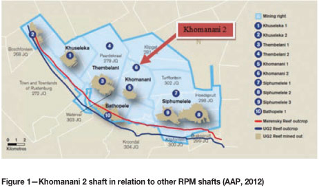
Khomanani mine is one of the Anglo American Platinum (AAP) division mines situated in the Rustenburg area, North West Province, South Africa. Figure 1 shows the location of Khomanani 2 shaft in relation to other Rustenburg Platinum Mines (RPM). The mine comprises two shaft systems namely, Khomanani 1 and Khomanani 2 shaft. Both the Merensky and UG2 reefs are mined at Khomanani. Khomanani 2 shaft makes use of conventional scattered-breast mining method for the extraction of the Merensky reef, and the UG2 is extracted by a hybrid method at Khomanani 1. The working depths of Khomanani 2 shaft are currently at approximately 1.2 km. The mine employed above 4 000 workers as at March 2012 (Modimoeng, 2012).
Geology
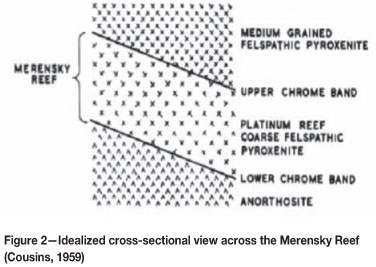
The mine is located on the western limb of the Bushveld Complex (BC), an extensive oval-shaped area hosting platinum (Merensky and UG 2 reefs) and chrome ore deposits. The Merensky Reef is underlain (footwall) by norite and overlain by pyroxenite (hangingwall). This platinum-bearing reef is mined at grades of up to 9 g/t total precious metals. Figure 2 shows the stratigraphy of the Merensky Reef.
Project background
This project was mooted following concerns from Khomanani management regarding a number of FOG experienced in stope areas. The mine currently uses 0.9 m long Hydrabolts as in-stope roofbolt support element in a 1.2 m high stoping width. These bolts have been employed for several years in the RPM section, and reports have been written previously for other mines regarding their uses. However, the investigations in this paper are limited to the use of in-stope roofbolts at Khomanani 2 shaft.
The FOG had fall-out thicknesses greater than the 0.9 m long Hydrabolts, ranging from 1.0 m to 1.3 m and averaging 1.1 m. The most susceptible sections were those associated with geological features such as, joints, domes, brows, and potholes.
The general feeling at the mine was that the FOG were occurring due to the Hydrabolt installation process. High-pressure water is pumped into the bolts for inflating of the bolt during the installation process. This results in the disturbance of the surrounding strata, and it has been thought that the 'key blocks' in the hangingwall may be displaced. In addition, the Hydrabolts are susceptible to corrosion, and it has been suggested that they lose their strength and efficiency over time as a result of this.
The objectives of the investigations described in this paper are:
► To mitigate the FOG experienced
► To find a suitable in-stope roofbolt support element capable of addressing the fall-out thicknesses
► To look at the implications of in-stope roofbolt support element on personnel safety, costs, and equipment requirements.
Scope of the study
This investigation is limited to face area roofbolt support installation, and not back areas and panels as a whole. Therefore support elements such as packs, props, and elongates will not be considered.
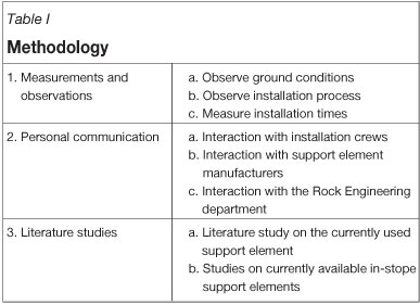
Methodology
A literature study was carried out on in-stope roofbolt support elements that can be used for immediate face support. In addition, observations were made at Khomanani 2 shaft, and ground conditions and the installation of the Hydrabolts were observed over three shifts. Although the ground conditions indicated joint sets, potholes, brows, and domes in some sections of the shaft, the conditions can be described as being average to good. The methodology employed in the investigations is summarized in Table I.
Literature study
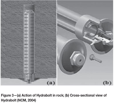
Hydrabolts are fabricated steel tubes with a 'C'-shaped cross-section sealed at both ends (New Concept Mining (NCM), 2004). They are friction bolts that work on high water pressure of 25 MPa. The pressure is provided by an underground-suitable pressure pump (NCM, 2004). There is a range of Hydrabolts (Table II). The Hydrabolts used in the RPM section are the NT-type, providing a capacity of 8 t. This provides a factor of safety (FOS) of approximately 1.6 that can be used to determine the possibility of support failure. Figure 3 shows the action of an installed Hydrabolt and the cross-sectional view of this 'C'-shaped bolt.
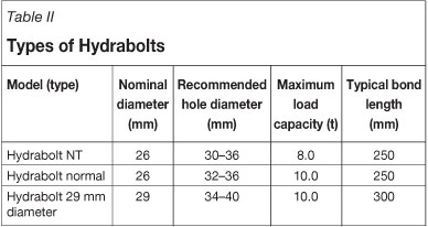
It can be seen from Table II that there are two types of Hydrabolt that have the same diameter but provide different capacities. This is because of the difference in the steel sheet used to make these bolts. The normal-types are 2 mm thicker than the NT-types, and as these bolts are frictional bolts, the extra 2 mm provides an additional 2 t capacity at the same bond length and diameter (Chamberlain, 2011). These bolts provide immediate resistance after installation and therefore are active supports (Yilmaz, 2012).
Hydrabolts have relatively few disadvantages, the most prominent of which is susceptibility to corrosion. The bolt has several advantages, including:
► Immediate support of the hangingwall
► Ease of installation
► A distributed support load in the drill-hole
► Flexible, therefore adapt to drill-hole's shape instantly
► Not susceptible to internal corrosion
► Resistant to abrasion and impact, and therefore can withstand blasting activities (NCM, 2004).
Further literature review showed that there are at least two mines in the RPM section that moved from one roofbolt support element to another due to issues of support length and bond length. These mines had fall-out thicknesses greater than the supported length and had to change to a longer tendon. One of these mines, Khuseleka 1 shaft (also owned by Anglo American Platinum) is currently experimenting with the use of cable anchors as an in-stope support element. This experiment is as a result of the implementation of cable anchors at another Anglo American Platinum mine, Dishaba (formerly known as Amandelbult). At both of these mines, mining takes place at stoping widths of between 1.2 m and 1.8 m in an underhand configuration ( van Aswegen and van Buuren, 2009).
Shaft 2 of Dishaba mine was experiencing an increased number of FOG in both the face and back areas, with incidents more prominent in the face area, over a period of one year. These FOG had a fall-out thickness just less than 1.5 m. At that time, 1m long tendons were being used - these were subsequently replaced by 1.5 m long cable anchors. High fall-out thicknesses were addressed by the introduction of 1.5 m long anchors (van Aswegen and van Buuren, 2009). The shaft now uses a 'timberless stope', thus only grout packs and cable anchors are used without elongates, as stipulated by van Aswegen and van Buuren (2009). Therefore, following this information, 1.5 m long cable anchors were further investigated by the authors to determine whether they can be used to replace the current Hydrabolts. The authors further looked at a variation of Hydrabolts, called RS bolts, and resin bolts as alternatives to Hydrabolts.
Resin bolts
Resin bolting is a chemical-type of grouted roof bolt that uses rigid bars for installation. These bolts can be used as either an active or a passive type of support, depending on the setting rate of the resin capsules employed (Yilmaz, 2012). The chemical 'grouting' is contained in a cartridge (capsule) with two compartments; one for a resin and the other one for a catalyst that helps in enhancing the bonding of the rockbolt to the rock surface during installation. During installation the cartridges (fast or slow setting resin or both) are inserted into the drill-hole, followed by a rigid rebar which is then spun using a rock drill (Hoek, 2007). The components of resin bolt can be seen in Figure 4.
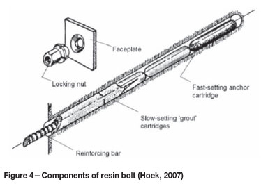
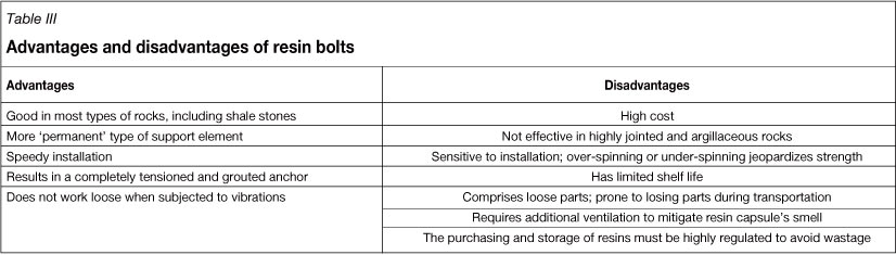
The spinning action facilitates the breaking of the cartridges, which then mixes the catalyst and the resin. The mixing enhances the bond strength of the anchor and speeds up curing time; hence these types of support elements are sensitive to installation. If the rebar is over-spun or under-spun it may compromise the strength of the resin and as a result reduce its efficiency. Figure 4 depicts a 'permanent-active' type of resin bolt where the fast-setting resin and then slow-setting resin are used in combination (Hoek, 2007). The advantages and disadvantages of using resin bolts are as shown in Table III.
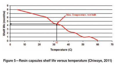
Tests were carried out for Khomanani mine as resin bolts are being used in advanced strike gullies (ASGs). The stiffness, hardening, flowability, and maximum shelf life of the resin against changing temperature were tested. Figure 5 shows the shelf life results obtained from these experiments. Shelf life decreases with increasing storage temperature. The maximum allowable underground temperature is approximately 32°C wet bulb, and from this it can be shown on the graph that the maximum shelf life of the resin is approximately 4 months. This therefore, emphasizes the point of having proper storage and regulated purchasing of resin capsules.
Cable anchors
Cable anchors are a flexible type of roofbolt support element made of steel wires. Cable anchors are suitable for use as in-stope roofbolt support due to their high flexibility, which allows them to be used in stoping widths less than the required supporting length. In addition to their flexibility, cable anchors are resistant to abrasion and impact, which makes them less susceptible to damage during blasting activities (Hoek, 2007). They are additionally less susceptible to corrosion due to grout usage during installation, which protects the drill-hole from groundwater ingress (Hoek, 2007). The earliest known use of cable anchors in the mining industry was in Free State, Geduld Mines Ltd (Thorn and Muller (1964), as cited in Hoek, 2007).
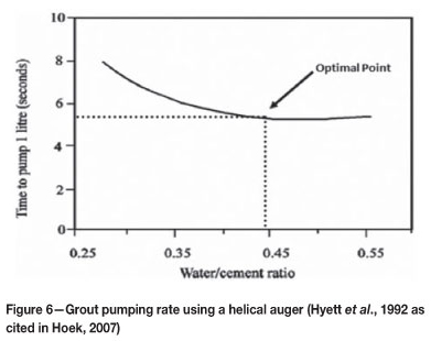
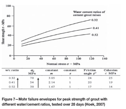
These anchors are passive-type of support (Yilmaz, 2012); displacement has to occur in the rock mass before cable anchor starts developing support resistance. The use of cement for grouting makes the installation of cable anchors more difficult. This is because the water-to-cement ratio of the grout must be regulated for the grout to settle in the drillhole and perform as required. Tests by Hyett et al. (1992) as cited in Hoek (2007) have shown that water/cement (w/c) ratios in the range of 0.35 to 0.45 are significantly better than w/c ratios in excess of 0.5, as can be seen in Figures 6 and 7. The results show that the grout with high w/c ratio is easier to pump; however, the compressive strength is compromised. A w/c ratio between 0.35 and 0.4 was found to be optimal. Figure 7 shows that the lower the w/c ratio, the higher the grout strength. Even though a higher grout strength is desirable, the pumping difficulties set a limit on the maximum w/c ratio that can be applied.
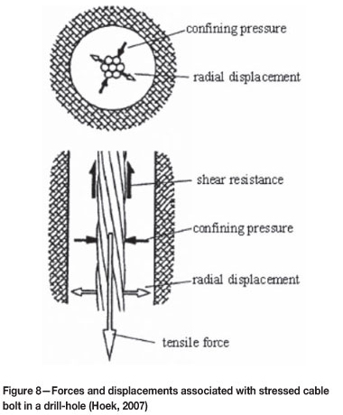
Once the grout has set in the drill-hole it is difficult for the cable anchor to be removed, hence cable anchors are favourable for permanent supporting rather than temporary. Figure 8 shows the forces and displacements associated with an installed cable bolt subjected to pulling action. According to Hoek (2007), if the cable bolt is pulled out of the grout, the resultant inference of the spiral steel imparts radial dilation of the interface between the grout and the cable bolt. This induces a confining pressure that is proportional to the combined stiffness of the grout and the surrounding drillhole; therefore, the movement is resisted by the shear strength, which increases with increasing confining pressure. This therefore causes the cable bolt to act as a friction bolt and a grouted bolt due to its increasing shear strength, thus yielding both grout and frictional bolt properties.
Installation of cable bolts
The installation of the cable bolts can be carried out in two ways, the breather-tube method or the grout-tube method (Figure 9). The breather-tube method (Figure 9a) is usually employed for grout having a w/c ratio of > 0.4, where grout is injected from the bottom through a large-diameter tube, typically 19 mm diameter (Hoek, 2007). The air in the grout is bled through a small-diameter tube attached together with the grouting tube onto the cable. This tube, called the breather tube, will notify the operator when the drillhole is full of grout, either by grout flowing directly into the hole or by the ceasing of air coming out of the hole (Hoek, 2007). However this method poses problems with the sealing off of the collar during pumping.
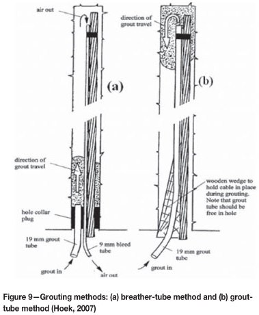
Alternatively, the grout-tube method, as shown in Figure 9b, can be used. A single larger diameter tube is taped to the cable bolt and used to inject the grout. According to Hoek (2007) a wooden wedge is normally used to plug the collar of the hole, and care must be taken not to squeeze the grout tube against the cable as this will hinder the grout pumping. The w/c ratio for this method ranges between 0.3 and 0.35 to avoid a high water content, which will result in air voids in the grout column as a result of grout slumping (Hoek, 2007). The grout-tube method provides an advantage over the breather-tube method as it is easier to determine when the column is full and the grout used is less susceptible to running through cracks due to the lower w/c ratio.
RS bolts
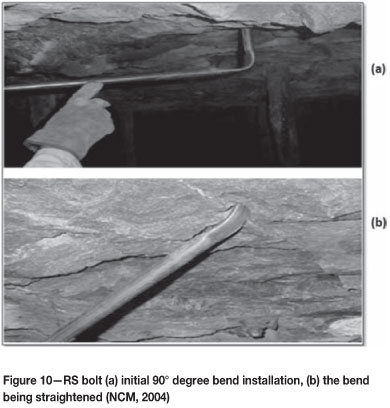
An RS bolt is another form of Hydrabolt, only longer and flexible enough to be used in stoping widths less than the supported length. The name RS bolts is given to Hydrabolts that incorporate a bend, for purposes of distinguishing between a longer straight Hydrabolts and a one with a bend (Chamberlain, 2012). RS bolts can have a 45°, 60°, or 90° bend for ease of installation in narrow stoping widths (New Concept Mining (NCM), 2004). During installation, the first part of the bolt is inserted into the drill-hole and when the bend is reached the bolt is straightened and further pushed into the hole, providing the support length required. This installation and straightening is done manually by the installer. Figure 10 shows the installation of a 90° bend RS bolt.
The use of Hydrabolts at RPM section
As mentioned previously, the shaft management at Khomanani had concerns regarding the use of Hydrabolts, the main concern being that the Hydrabolt installation induces FOG due to the expansion action. Tests have been carried out by Rock Mechanics Technology (RMT) (2004), SRK (2009), and Groundwork Consulting (2006) to investigate this possibility. The results obtained from these independent investigations were similar and are as shown in Appendix A. The overall conclusion was that the Hydrabolts cannot cause displacement large enough to dislodge any loose rock in the hangingwall. Therefore, Hydrabolts (or any variation of these bolts) still remain as a possible solution to the problem at hand.
Observations
Underground observations
Observations were carried out underground on sections utilizing the Hydrabolts, paying particular attention to the installation process and ground conditions. It was observed that the Hydrabolts were installed once the drilling of all the holes was completed in a panel. However, Hoek and Wood (1987) state that friction bolts are installed at the face area because they are not tensioned, and therefore should be installed before significant movement occurs in the hangingwall. The safety procedures drafted by the manufacturers of the Hydrabolts also state that a Hydrabolt should be installed immediately after a drill-hole is completed (NCM, 2004).
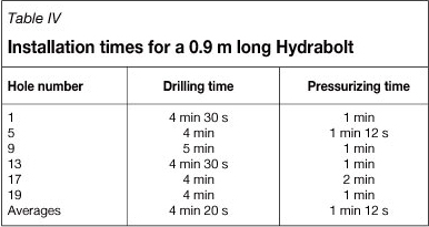
Communications with the Hydrabolt installation crew helped with the identification of a further problem; the support installation was done concurrently with the face drilling and installation of elongates, which caused the 6-outlet manifolds being used for compressed air to be inadequate for drilling of a support hole for the installation of Hydrabolts. There are three rockdrill operators at a given time; one for the Hydrabolt crew, one for the elongate crew, and one for drying blastholes for explosive pumping at a later stage. Furthermore, the time it takes for one Hydrabolt to be installed was recorded and averaged as shown in Table IV. The time study was done for 0.9 m long Hydrabolts on a 35 m long panel having 19 holes, and every fourth hole was timed. Hydrabolt holes were drilled by an in-stope roof bolter as shown in Figure 11. The measured times are subject to change depending on the installation crew at the time, and take into account delays incurred while in operation.
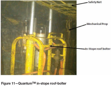
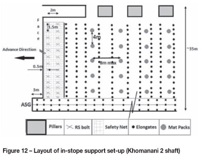
Hydrabolts are installed 0.5 m from the face, 2 m on dip, and 1.5 m on strike. This can be seen in a plan view shown in Figure 12. Hydrabolts are installed in conjunction with the mechanical props and safety nets to improve safety of the mining crews. Hydrabolt holes are drilled adjacent to the mechanical props. Two operators are involved in the installation of Hydrabolts; one handles the Hydrabolt in the stope and the other manages the underground high-pressure air pump. Figure 11 shows the photo (taken on-site by the first author) of the in-stope roof-bolter, known as Quantum at the shaft, due to its 'remote control' function and rubber tyres.
Corrosion
As mentioned earlier, the corrosion of Hydrabolts was thought to be one of the factors reducing their efficiency and hence increasing the likelihood of FOG. However, the authors are of the opinion that this is not the case. Hydrabolts are used as temporary support, and their location 6 months after their installation is classified as a 'back' or old area. Hence, by the time that corrosion would become an issue, no mining activity takes place in such areas, and the entry of mineworkers is prohibited. Therefore, in such old areas corrosion does not become a factor of concern, since any FOG would take place in the absence of workers. In addition, Hydrabolts are designed so that corrosion affects only the outer part of the bolts and not the inner parts (NCM, 2004). Therefore, the chance of a Hydrabolt losing its effectiveness due to corrosion becomes minimized and even if that occurs, the bolt will act as an 'X-pandabolt' as stipulated by Chamberlain (2012). These are similar to Hydrabolts but release water once installed and therefore withstand more deformation. This enables the X-pandabolt to withstand greater lateral movement of the rock in which it is installed than the Hydrabolt (NCM, 2004).
Analysis of results
A practical approach is adopted in analysing the results obtained from the literature review and observations. The most important point of consideration is whether the selected in-stope roofbolt support would be installed without disturbing routine stoping activities. Men, material, machinery, and money (the 'Four Ms') become important considerations for those in-stope rockbolt types passing the implementable stage. The costs, face-area safety improvements, and whether or not additional equipment will be required would also be looked at carefully before any decision-making. In addition to the Four Ms, it is essential to maintain productivity with minimal disturbance to stoping activities.
Resin bolts
The resin bolts make use of rigid rebars as support reinforcement. Rigid rebars in turn impede the bolt's flexibility and cannot be employed in stoping widths less than the required support length. Table III indicates that the resin bolts have numerous loose parts which may be lost during transportation, and these bolts are sensitive to the w/c ratio during installation. Although resin bolts would provide sufficient support resistance for good hangingwall conditions, they are not good in jointed rocks. If one of the resin components 'runs' through the joint, the resin will not set properly, and thus virtually no bond strength would be developed. The shelf life of resins is another concern that requires careful monitoring. Furthermore, the smell of resin bolts would be unpleasant to the stoping crews if adequate ventilation is not provided. In such a case (which is a possibility), the workers would rush to complete their duties, consequently leading to poor installations and compromising the quality of support installation and safety.
Cable anchors
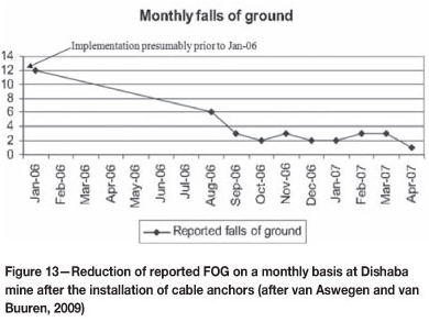
Cable anchors are flexible, and can be used in stoping widths less than the required support length. The transportation of these anchors also involves many parts, although the number of parts involved for cable anchors is less than for resin bolts, and cable anchor parts are assembled into a unit on surface. The safety of mineworkers would increase due to the increased support resistance provided by these bolts. Cable anchors would satisfy the required support length of 1.1 m by using a 1.5 m long anchor in a 1.2 m stoping width. The FOG experienced would consequently be reduced. Dishaba mine experienced a dramatic decrease in FOG after the implementation of cable anchors, as can be seen in Figure 13.
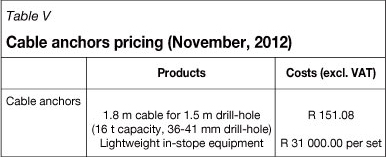
However, cable anchors would require additional sets of installation equipment that would result in the increase of support costs by 140%, as experienced at Dishaba mine. Table V shows costs associated with cable anchors as per November 2012 (Mathews, 2012). It can be seen that a 1.8 m long cable anchor is required for a 1.5 m long drill hole, where an additional 300 mm is used for tensioning. Mathews (2012) advises that two sets of installation equipment should be available, to maintain productivity and to avoid delays during breakdowns. Additionally, it can be seen from Table V that cable anchors provide more capacity (16 t) than the currently employed tendons (8 t). Excess support capacity would require a re-structuring of the support patterns to accommodate cable anchors and to maintain a factor of safety of 1.6 or 1.8. Implementation of cable anchors would also require training of support crews, as this support element is not employed in any part of Khomanani 2. The additional training would increase the support costs.
RS bolts
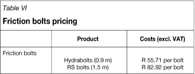
RS bolts are essentially similar to the Hydrabolts currently being employed, only longer. Their ability to bend allows for a longer version of their type to be used in stoping widths less than the required support length. RS bolts are easy to transport, since they consist of only one bolt, and consequently are easy to install. It is worth mentioning that further training and familiarization of installation crews with this bolt will have to be conducted, preferably on-the-job training. This will assist in removing concerns that might be raised regarding the bending effect of the bolt. Since the longer RS bolt may address the fall-out thickness, there would be increased safety for mineworkers due to the reduction of number of FOG occurring. The cost with this type of support element increases by 50% due to the discrepancies in the bolt lengths, as can be seen in Table VI. The equipment used will remain the same as that currently employed with Hydrabolts. However, productivity levels may decrease due to the requirement for drilling longer holes, which would increase the time required for the completion of RS bolt installation. Increasing the number of manifold outlets could be considered as a measure to maintain productivity.
Conclusions
The currently employed 0.9 m Hydrabolts do not provide adequate in-stope support, due to the short bolt length. A longer tendon is required to account for the fall-out thicknesses experienced. The underground observations assisted in the identification of inadequacies in the support installation due to this factor. The incorrect manifold size was particularly a concern. It has additionally been shown that no matter which roofbolt type is selected, the cost of support will increase with increasing support length.
In addition, the installation procedure for Hydrabolts does not contribute to FOG, even as close as 0.3 m to the geological structures. Corrosion of the Hydrabolts in the old mined-out areas would also not to be a factor for concern in the occurrence of FOG. The use of a longer bolt will increase installation time, and as a result productivity will drop and measures would have to be taken to maintain productivity. Resin bolts have proved to be less effective in stoping widths less than the required support length. Therefore, the only possible substitutes for 0.9 m Hydrabolts are 1.5 m long cable anchors or RS bolts. Cable anchors and RS bolts have been shown to increase face-area support costs by up to 140% and 50% respectively. Apart from the cost consideration, cable anchors require a re-design of the support pattern and new training for support-installation crews.
Recommendations
► The RS bolts should be implemented in the sections with a high incidence of FOG, and the results assessed over a period of 6 months
► The implementation should not be a 'blanket application' in order to maintain productivity, and the ground conditions and numerous geological features should be taken into account
► Manifold size should be increased from 6 outlet to 8 outlet to address the inadequacies in the installation of in-stope roofbolts. This will reduce the standing time for the completion of the drilled hole and speed up the roofbolt installation
► The bolts can be coated with oil or bitumen solution, as once practiced on Swellex dowels (Plotz, 2012), should corrosion become problematic.
Further work is recommended to determine whether the installation of RS bolts should be extended throughout the mine, or confined to the sections with a high incidence of FOG.
Acknowledgements
The following persons and organizations are thanked for their help in conducting this project. Anglo American Platinum, together with the Anglo American Technical Division, who provided the project topic and gave permission for publication of the results. Ms P. Nkwadi for assistance and guidance, together with Henry Chiwaye, Amma Boaduo, and the manufacturers of in-stope roofbolt products.
References
Anglo American Platinum Limited. 2012. Khomanani Mine. http://www.angloplatinum.com/business/operations/khomanani_mine.asp [Accessed 19 April 2012] [ Links ].
Cawthorn, R.G. 2010. The platinum group elements deposits of the Bushveld Complex in South Africa. http://www.platinummetalsreview.com/article/54/4/205-215/ [Accessed 14 May 201] [ Links ].
Chamberlain, I. 2012. Discussion of the Hydrabolts. New Concept Mining, sales manager. Personal communication [telephone], 12 January 2012. [ Links ]
Chiwaye, H. 2011. Discussion of the Hydrabolts. Shaft Rock-Engineer at Khomanani 1 shaft. Personal communication, 13 December 2011. [ Links ]
Hoek, E. 2007. Rockbolts and Cables. .Practical Rock Engineering. http://www.rocscience.com/hoek/corner/14_Rockbolts_and_cables.pdf [Accessed 21 March 2012] [ Links ].
Hoek, E. 2007. Support of underground excavations in hard rock. Practical Rock Engineering. http://www.rocscience.com/hoek/corner/Support_of_Underground_Excavations_in_Hard_Rock.pdf [Accessed 21 March 2012] [ Links ].
Hoek, E. and Wood, D.F. 1987. Support in Underground Hard Rock Mines. Canadian institute of Mining and Metallurgy, Montreal. . http://www.rocscience.com/hoek/references/H1987a.pdf [Accessed 2 May 2012] [ Links ].
Jones, R.T. 1999. Platinum smelting in South Africa. http://www.mintek.co.za/Pyromet/Platinum/Platinum.htm [Accessed 20 April 2012] [ Links ].
Mathews, D. 2012. Discussion of the cable anchors. M&J Company, Sales Director. Personal communication [email]. 11 January 2012. [ Links ]
Modimoeng, D. 2012. Labour numbers and categorization of labour. Human Resource Department, Khomanani 2 mine, Rustenburg Platinum MinesPersonal Communication. [email], 6 March 2012. [ Links ]
More O'Ferrall, G.C. 2009. Use of Hydrabolts in the Bushveld Complex platinum mining industry - Khomanani Mine, Rustenburg Platinum Mine. SRK Consulting Engineers and Scientists. Report No. 407932. [ Links ]
New Concept Mining. 2004. Hydrabolts. http://www.ncm.co.za/hydrabolt.html [Accessed 20 April 2012] [ Links ].
New Concept Mining. 2004. RS bolts. http://www.ncm.co.za/rs-bolt.html [Accessed 20 April 2012] [ Links ].
Plotz, G. 2012. Discussion on corrosion effects on the Swellexdowel. [ Links ]
Production Specialist, Atlas Copco. Personal communication [email], 13 January 2012. [ Links ]
Pullen, D. 2004. Investigation into rock movement caused by the installation of Hydrabolts, conducted at Lebowa and Rustenburg Platinum mine. Hydrabolt Rock Movement Tests. Report no. 040006. Rock Mechanics Technology Ltd. [ Links ]
Van Aswegen, L. and van Buuren, S. 2009. Review of face area support for Amandelbult No. 2 shaft and subsequent introduction of cable anchors. Southern African Institute of Mining and Metallurgy and South African National Institute of Rock Engineering. http://www.saimm.co.za/Conferences/GroundSupport2008/707-720_van%20Aswegen.pdf [Accessed 28 April 2012] [ Links ].
Van Vuuren, J.J. and Piper, P.S (reviewer). 2006. Hangingwall displacement measurements during Hydrabolt installations. Testing Report prepared for New Concept Mining. Groundwork Consulting (Pty) Ltd. Report no.CR264/0806/NCM004. [ Links ]
Yilmaz, H. 2012. Installed support. Lecture to BSc Mining Engineering, 4th year. University of Witwatersrand, Johannesburg, South Africa. 23 April 2012. [ Links ]
Paper received Dec. 2013
Revised paper received Dec. 2013.
Paper written on project work carried out in partial fulfilment of Bsc. Eng (Mining Engineering)
© The Southern African Institute of Mining and Metallurgy, 2013. ISSN2225-6253.
Appendix A
Results of independent investigations of Hydrabolts
SRK Consulting
The following results were obtained by SRK Consulting (2009), following a statement by the Chief Inspector of Mines that Hydrabolts are not suitable for support in Bushveld Complex formations.
► The Hydrabolt is a tubular support unit providing radial forces on the hole rock wall
► The positive forces against the rock wall ensure that the Hydrabolt does not slip or loosen when exposed to blasting vibrations
► These tests showed that the Hydrabolt does not fracture the rock to an extent sufficient to cause instability
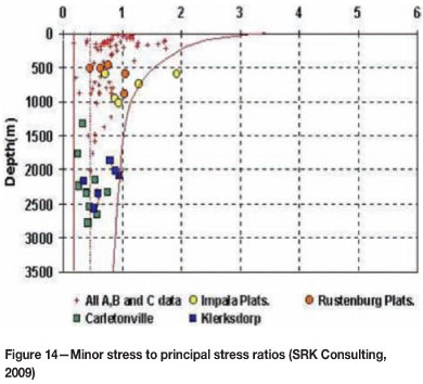
►The magnitude of the horizontal stresses exceeds that of the vertical stress component for the majority of average depths in the platinum industry (Figure 14)
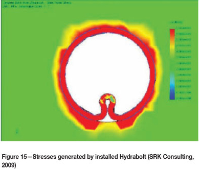
► F urthermore, Merensky Reef FOG are typically gravity-induced and maybe bound by a stress fracture at the upper boundaries. Figure 15 shows an infinite boundary element test carried out on the installation of the Hydrabolt. This indicates that the installation of Hydrabolts into a solid pre-stressed rock mass actually reduces the effects of existing stress concentration around the support hole created. Moreover, the forces (radial) generated against the rock mass by these bolts dissipate within 3 mm of the bolt.
Groundwork Consulting
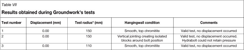
The following results were obtained by Groundwork Consulting after a Hydrabolt customer raised concerns about the Hydrabolt installation process. The concerns pertained to the mechanical behaviour of the Hydrabolt during inflation, and centred around a possible axial tension that could affect the rock around the Hydrabolt. The test results were obtained using a sensitive gauge able to measure displacements of 0.01 mm.
► Displacement was not detected in the hangingwall during Hydrabolt installation (Table VII)
► The difference between the hole diameter (37 mm) and the Hydrabolt (27 mm) may have led to a large clearance space for the steel to expand sufficiently before coming into contact with the rock mass
► The axial tension that the Hydrabolt can transmit onto the rock wall is a function of hole diameter, the rate of expansion the profile of the hole, and the contact shear strength between the rock and the steel. Therefore, the full expansion of the bolts during inflation may not fully transmit forces to the surrounding rock.
Rock Mechanics Technology (RMT) Limited
The following results were obtained by RMT from tests carried out on the NT-type Hydrabolt at Lebowa and Rustenburg Platinum Mines. The objective was to investigate the bolts' stability surrounding the rock mass during installation, especially near brows. An additional, aim was to test the influence of the bolts on the loosening and opening of joint sets, tension cracks, or even propagation of cracks.
► The test procedure was considered conclusive and successful, measuring both the elastic and inelastic response to the installation of Hydrabolts
► The tests indicated that installation of Hydrabolts near the edges of brows does not cause rock fracturing
► Installation of the Hydrabolt as close as 300 mm from the edge of the brow did not cause sufficient movement to cause failure of the rock. Noting that mine standards use 500 mm either side of discontinuities, inclusive of brows
► A Hydrabolt was also installed in an existing crack, and movement was observed but did not cause any failure of the brow. (However, the author does not recommend this to be done, as it was only a measure taken by RMT to illustrate the insignificance of Hydrabolt expansion).

