


Serviços Personalizados
Artigo
 Inglês (pdf)
 Artigo em XML
 Referências do artigo
Indicadores

Links relacionados
-
 Citado por Google
 -
 Similares em Google
Compartilhar

 Permalink
Journal of the Southern African Institute of Mining and Metallurgy
versão On-line ISSN 2411-9717
versão impressa ISSN 2225-6253
J. S. Afr. Inst. Min. Metall. vol.113 no.4 Johannesburg Abr. 2013
PAPERS
Continuous blasting improvements at Landau Colliery
M. Rakoma
Department of Mining Engineering, University of Pretoria
ABSTRACT
Following the blasting fatality on 17 December 2009, Landau Colliery was forced to change from the blasting practices that had been utilized since the start-up of the mine. Since then, attempts have been made to optimize blasting results. The challenge is rooted to the mining environment - during the early life of the mine, mining took place in virgin areas, whereas currently mining is taking place in areas overlying old underground bord and pillar workings. The underground bord and pillar workings aggravate phenomena such as spontaneous combustion, hot holes, and sinkholes. The 2009 fatality was attributed to hot holes causing premature detonation. Landau has been struggling with poor results from their overburden and coal blasts; leading to poor fragmentation of overburden and the P1 parting that lies between the No.1 and No.2 coal seams.
An extensive literature survey was completed in order to identify possible alternative solutions that could be evaluated for this unique mining environment, which demands a high degree of caution during mining to ensure factors such as dragline stability and personnel safety. The literature survey confirmed that the previous blasting technique, which was mainly characterized by air decking, was indeed the more efficient, although it was deemed unsafe because of the possibility of hot holes and the high sensitivity of detonators.
Potential modifications to the blasting technique were modelled in a Microsoft Excel simulation that was available from the mine, and pit visits were conducted in order to determine whether implementation would be a problem. From the model it is evident that results can be improved by changing the current burden and spacing ratio. Visiting the pit revealed that the tie-in pattern and drilling inaccuracies are contributing to problem areas.
Keywords: optimize, spontaneous combustion, sinkholes, hot holes, premature detonation.
Introduction
Mine background and general information
Landau Colliery is one of two Anglo American Thermal Coal (AATC) opencast mines that have sections in operation over old underground workings. The underground operation was a bord and pillar operation that started in 1922 and was called Coronation Colliery. Coronation Colliery ceased operation in 1966, and in 1992 Kromdraai started up as a single dragline operation. Currently Landau consists of three other mini-pits namely, Schoongezicht, Umlalazi and Excelsior, however the mention of Landau is widely attributed to Kromdraai.
Kromdraai is situated 14 km north-west of Witbank, and is connected to the Navigation plant 6 km to the west of Witbank, by a 23 km mine-owned railway line that transports the run-of-mine coal from Kromdraai to the plant.
Project background
After the fatality on 17 November 2009 due to premature detonation, the blasting technique, which at the time provided satisfactory results, had to be changed. Figure 1 illustrates the 'gas-bag' air decking technique that was used prior to the fatality.

Since then, attempts have been made to achieve similar satisfactory blast results but this has proven to be difficult. The more recent attempts involved the use of manta-locks instead of gas bags, together with less heat-sensitive downhole blast accessories. Figure 2 illustrates the 'manta-lock' air decking technique.
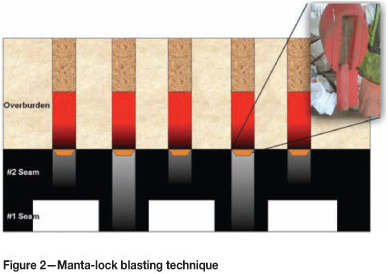
Manta-locks, which are hardened plastic decking accessories, were used similarly to the gas bags to carry the load of the charge. However this resulted in poor blast results, leading to poor fragmentation of the coal seams (illustrated in Figures 3 and 4), as well as of the P1 parting, which has a thickness of more than 1 m in certain areas (Figures 5 and 6). Furthermore, during overburden loading by the dragline a significant amount of hard digging is encountered. The scaling object (yellow hard hat) in the photographs indicates the extent of the poor fragmentation, which is generally regarded as material sizes above 1 m.


Objectives
The objectives of the investigation were to
► Investigate the causes of poor blast results
► Model the blast results of potential solutions and their impact on fragmentation or powder factor etc.
► Simulate and model the effects of varying the individual blast parameters and compare the results
► Determine methods to improve blast results
► Conduct a cost analysis of the current blasting method compared to potential solutions (cost per bank cubic metre)).
Methodology
► A literature study was conducted which provided background on opencast mining above old underground workings, the development of a mining technique for such a situation, and the reasons for certain blasting techniques. The investigation on the poor blast results consisted mainly of pit visits, reviewing old blast reports, and consulting the relevant management personnel and miners
► A Excel simulation model was acquired from the mine, that provided a way of changing various blasting parameters to determine their impact on fragmentation size, costs, and powder factors. However, this was only on a design basis; in areas where the ideal competent rock does not occur, using the model in isolation will not reflect the actual results
► Methods to improve blast results were obtained mostly from interviews with the miners and management. In most cases the miners proposed useful solutions, although they could not substantiate them properly to management for implementation
► Implementation errors such as drilling and blast delay timing were determined and simulated in order to evaluate their impact on blast results
► The blast parameters were varied to model about seven different scenarios that were occurring in order to determine the sensitivity of the results to certain parameters and make recommendations.
Results
The two blasting techniques involved major changes, from ceasing the air decking system to drilling through the pillars, as well as minor changes such as increasing the explosive density and blast-hole diameters.
Manta-lock blasting technique
In Figure 7, the following blast design and technique was employed:

► Drilling through pillar centres from overburden to No.1 seam floor
► Drilling 1 m into the P1 parting or 0.5 m into the No.2 seam bords
► Air decking using manta-locks
► Emulsion blend of density 1.01 g/cm3 (cup density)
► Pentolite booster and detonating cord
► 19 mm slag (stemming material)
► Ø250 mm blast-hole diameter
► Burden: 6.1 m
► Spacing: 12.2 m
► Trunkline delays of 100 ms for inter-holes and 42 ms for inter-rows as illustrated in Figure 8.
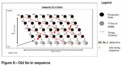
Apart from the visible results, a considerable amount of top-ups (extra charging) was being done, where the charge column would displace downwards because the manta-locks would fail and fall to the blast-hole floor, thus leaving the booster suspended in the air and consequently causing a misfire or sympathetic detonation, as can be seen in Figure 9 (Moloto, 2011).

Current blasting technique
After the top-ups were discovered (Figure 9), the blasting technique and design that was employed during the study was implemented. This blasting technique, which was motivated by the poor results obtained using the manta-lock blasting technique, is as illustrated in Figure 10.

► Drilling only to top-of-coal (No.2 seam)
► In areas of thick parting, drilling 1 m into the P1 parting
► Emulsion blend of density 1.15 g/cm3 (cup density)
► Pentolite booster and detonating cord
► Approximately 70 mm crushed and drill chippings (Stemming material)*
► Ø311 mm blast-hole diameter
► Burden: 6.1 m
► Spacing: 12.2 m
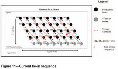
►Trunkline delays of 42 ms for inter-holes and 100 ms for inter-rows, as illustrated in Figure 11, due to a significant amount of misfires that were discovered with the previous tie-in sequence.
*Nominal crushed rock size from semi-mobile crusher on site, which falls within the range of 10% of the blast-hole diameter (Ø311 mm).
According to Moloto (2011), the decision not to drill to bottom-of-coal was a result of the failure of the previous decking system used, which proved that it was pointless to drill to bottom-of-coal. However, this has recently given rise to other problems, such as poor fragmentation of the P1 parting, mining unblasted coal pillars, and hard digging. The increase in explosive density was due to an increasing number of wet holes that were encountered.
Finally, one of the most typical although important blasting parameters to be changed was the blast-hole diameter. Increasing the diameter increases the powder factor and thus increases the power of the blast; this in blasting terms is called 'hitting harder'. The previous blast-hole diameter of Ø250 mm delivered a powder factor of 0.5 kg per BCM, while Ø311 mm delivers a powder factor of 0.7 kg per BCM. This was motivated by the frequent hard digging and large boulders that were encountered.
Pit visits
In any blast design, typical implementation errors can be found in the drilling, tie-in sequence, charge column length, and consequently stemming length. Amongst these, the drilling errors have the most impact on blast results. If a hole is misplaced by 0.5 m it could reduce the explosive power by 35% (Neale, 2010).
At Kromdraai the overburden in the current mining area contains a high ratio of soft material to hard material - about 1.16 to 2. Therefore a 15 m bench will consist of about 7 m of 'softs', thus aggravating poor drilling and blast-hole contamination and loss of explosive energy through poor distribution.
According to De Graaf (2011), drilling in the incorrect position or abandoning drilled holes, as illustrated in Figure 12, leads to poor results in terms of fragmentation and potential capping. Drilling to shallow depths is the major cause of capping and hard digging, as illustrated in Figure 13 (Moloto, 2011).


Figure 14 shows the findings from the pit visits, through measuring about 100 blast-holes from Cut 21 and 22 and also from blast reports for Cut 20. Besides the fact that Cut 21 and 22 were where mining was being carried out during the study, these areas are also those where problems were encountered with thick P1 parting and hot holes, thus they served as representative areas for the study.

Figure 14 illustrates the variance between the drilled depth and the depth measured prior to charging and blasting. As per Landau drilling practice, blast-holes measured prior to charging that vary more than 1 m from the planned depth must be re-drilled. The lag between drilling and blasting is about 2 days. However, over the recent holiday season, (e.g. 2012 Christmas and New Years), during which drilling activity continued while blasting activity was halted, the blast-holes were observed to have a variance of about 5 m to 7 m from the drilled depth, and this resulted in further poor blast results.
The reason for this is that for normal drilling and blasting scheduling, contaminations (i.e. collapse of drilled hole or presence of water from rain or underground reservoirs) of about 1 m are observed, as illustrated in Figure 14. Over longer periods of time, where the schedule cycle is longer or interrupted, the contamination will also increase.
Quality control
Finally, during the pit visits it was observed that the tie-in sequence was incorrect. The surface shock tube delays were connected in a square pattern, while the design requires a staggered pattern.
Figure 15 illustrates the impact of tying-in 2 x 42 ms surface shock tube delays in areas where there should only be a single 42 ms delay. The summation of the two delays results in about 84 ms delay in those areas compared with the designed 42ms. This error results in an increased inter-hole distance between blast-holes, which leads to the blast being out of sequence, the possibility of cut-offs, and lack of interaction between the blast-holes.

Fragmentation prediction (Populated Kuz-Ram)
The blast design was evaluated through the fragmentation prediction model in order to determine the expected theoretical fragmentation and use this information to determine the sensitivity to varying certain blasting parameters. A simulation model was available, and after considering the different scenarios that Kromdraai can be faced with, seven scenarios were varied and compared to the base case (current blasting technique). The sensitivity to each parameter was measured in terms of variance from the predicted fragmentation size, which is represented as a percentage. A number of fragmentation prediction models other than the Populated Kuz-Ram exist (e.g. the Modified Kuz-Ram (Swebric equations) and Sabrex (Muckpile profiles)), however, these were not available from the mine. The Populated Kuz-Ram is derived from the Kuz-Ram model of the 1980s and since then it has been adapted by increasing the confidence of certain variables and so forth, as can be observed in the Kuznetsov equation.
The Populated Kuz-Ram was the only program available which had the followin limitations of the model:
► Inability to predict fines generation
► Lack of input of timing effect
► Lack of detailed geomechanics information
► Over-estimation of the fragmentation size (50% passing size).
The advantages of the model are:
► Simple to utilize
► Requires few variables/parameters
► Cheap (Excel program)
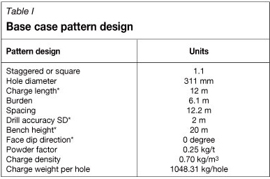
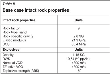
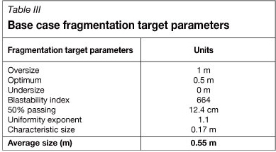
►Easily illustrates sensitivity to changing parameters The base case is illustrated in Table I. The model allows for a drilling accuracy standard deviation input (SD*) and a face dip direction input in combination with the typical blasting parameters. However, Table II illustrates the abovementioned lack of detailed geomechanics information and timing effects. The base case average fragmentation size is 0.55 m, which was the parameter of comparison between the six scenarios as illustrated in Table III.
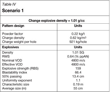
► Scenario 1-Changing the explosives density from the current 1.15 g/cm3 to 1.01 g/cm3 resulted in a 8.6% change in the average fragmentation size (Table IV)
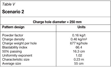
► Scenario 2-Changing the hole diameter from the current 311 mm to 250 mm resulted in a 21.5% change in the average fragmentation size (Table V)
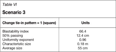
► Scenario 3-Changing the tie-in pattern from staggered (1.1) to square (1.0) resulted in no change in the average fragmentation size (Table VI)
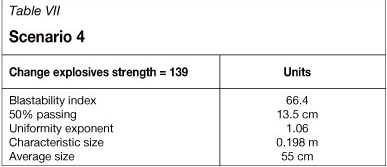
► Scenario 4-Changing the explosives strength (RBS) from the current 159 to 139 resulted in a 8.9% change in the average fragmentation size (Table VII)
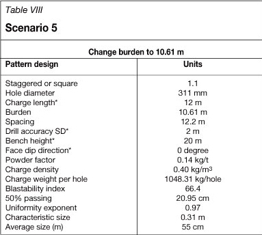
► Scenario 5-Changing the burden to spacing ratio from the current 2 to 1.15 (rule of thumb), by increasing the burden distance from 6.1 m to 10.61 m resulted in a 69.5% change in the average fragmentation size (Table VIII)
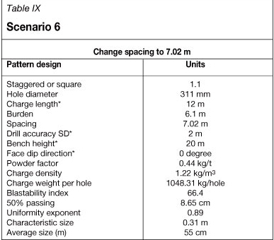
► Scenario 6-Changing the burden to spacing ratio from the current 2 to 1.15 (rule of thumb), by reducing the spacing from 12.2 m to 7.02 m resulted in a 43% change in the average fragmentation size (Table IX)
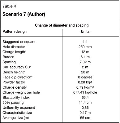
► Scenario 7-Changing the hole diameter and the spacing (i.e. scenarios 2 and 6) resulted in a change of only 8% in the average fragmentation size (Table X).
The seven scenarios are summarized in Figure 16. It can be seen that the burden distance is the parameter with the greatest effect.

Costs per BCM
The costs per bank cubic metre are a function of three parameters, namely drilling costs, explosives costs, and initiation systems costs. Table XI illustrates the increasing cost of the old, current, and proposed design. However the additional drilling costs (excluding additional blasting costs) are justified in view of the advantages of the proposed design, as illustrated in Table XII.


Conclusions
The main causes for the poor blast results are as follows:
► Drilling deviations (contamination and abandoning of holes)
► Tie-in sequencing (quality control)
► High softs to hards ratio (1.16-2)
► High spacing to burden ratio of 2.
The results from the sensitivity analysis indicate which parameters can be changed in the design in order to continuously improve blasts, which are affected by the varying geology.
Recommendations
The recommendations in order to improve blast results are as follows:
► Adjust the spacing to burden ratio to 1.15 (scenario 6)
► Holes should be charged and blasted within 24 hours of drilling
► Monitor and audit tie-in sequence
► Conduct a localized investigation into angle deviations (bore tracking)
► Communicate changes in different charging scenarios more efficiently.
Recommendations for further research
► Investigate how to mitigate the effects of the high softs to hards ratio (overburden softs to hards ratio of 1.16-2)
► Investigate the feasibility of other decking systems
► Blasting shift analysis to match drilling rate.
References
BME. 2011. Charging hot holes to extract remaining coal from old underground workings. http://www.miningweekly.com/.../charging-hot-holes-to-extract-remaining [Accessed 18 December 2011] [ Links ].
Clough, W.D. and Morris, R. The opencast mining of previously underground-mined coal seams. Journal of the Southern African Institute of Mining and Metallurgy, vol. 85, no. 12. pp. 435-439. [ Links ]
De Graaf, W.W. 2012. Personal communication. University of Pretoria. [ Links ]
Cunningham, V.B. 1986. The Kuz-Ram model for prediction of fragmentation from blasting. 1st International Symposium on Rock Fragmentation by Blasting, Lulea, Sweden. [ Links ]
Laybourne, R.A. and Watts, R. The development and application of strip mining to previously mined underground coal workings. Journal of the Southern African Institute of Mining and Metallurgy, vol. 90, no. 8. pp. 187-197. [ Links ]
Mangope, V. Personal communication. Anglo American Thermal Coal Technical Services, [ Links ]
Moloto, J. 2011. Personal communication. Anglo American Thermal Coal. [ Links ]
Neale, M. Blast optimization at Kriel Colliery. Journal of the Southern African Institute of Mining and Metallurgy, vol. 110, no. 4. pp.161-168. [ Links ]
Strachan, T. 2008. Presentation to New Vaal Colliery management. 4 July. [ Links ]
Paper received Jan. 2012
Revised paper received Jan. 2012.
Paper written on project work carried out in partial fulfilment of B. Eng (Mining)
© The Southern African Institute of Mining and Metallurgy, 2013. ISSN2225-6253.

