


Serviços Personalizados
Artigo
 Inglês (pdf)
 Artigo em XML
 Referências do artigo
Indicadores

Links relacionados
-
 Citado por Google
 -
 Similares em Google
Compartilhar

 Permalink
Journal of the Southern African Institute of Mining and Metallurgy
versão On-line ISSN 2411-9717
versão impressa ISSN 2225-6253
J. S. Afr. Inst. Min. Metall. vol.113 no.3 Johannesburg Mar. 2013
PLATINUM CONFERENCE 2012
Applications and benefits of 3D laser scanning for the mining industry
J.W. van der MerweI; D.C. AndersenII
IPMS, Anglo American, Johannesburg, South Africa
IIPlato, MBA
SYNOPSIS
Technology is advancing at a rate that makes it extremely difficult for the mining industry to keep pace. Many advances occur within a given piece of technology and often this is missed by the disciplines that could have gained advantage by its implementation. Often this may have been simply an aspect of cost exceeding benefit.
However, there are some technologies that potentially have such a far-reaching impact on the mining industry that the benefits simply outweigh the cost. The application of 3D laser scanning in the mining industry has the potential of taking the concept of 'Google mapsTM' underground. This presents an opportunity where the virtual world of underground can be traversed with relative ease and many aspects of measurements could be obtained without having to visit the working place again, potentially saving countless man-hours and still delivering precision work with significant savings in downtime, stoppages, and exposure to safety incidents.
Anglo American Platinum maintains its competitive advantage though the review and application of appropriate technology. This paper describes the 3D laser scanning trial at one of Anglo American Platinum's new shafts, and goes on to show the benefits encountered through the application and the involvement of the various MRM disciplines.
Keywords: 3D - Three Dimensional, GPS - Global Positioning System, CAD -Computer Aided Design, CFD - Computational Fluid Dynamics.
Introduction
3D laser scanning captures spatial data by the use of laser light. The shape, position, and spatial locations of objects are recorded by millions of points, each with latitude, longitude, and elevation (xyz) co-ordinates.
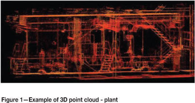
3D laser scanning uses a high-speed laser scanner with a 360° field of view around the horizontal axis and 270° around the vertical axis, with the shadow vertically below the instrument. The laser scanner is able to scan any structure within its field of view and create a complete data set in the form of a 3D point cloud (Figure 1) made up of millions of points of data. As every point is coordinated, distances can be measured between points in AutoCADTM to millimetre accuracy. Quick, complete surface geometry is safely and accurately captured with the 3D laser scanner.
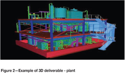
The raw scanner data, or 3D point cloud, can be used with the appropriate software to view, pan, zoom, and rotate in 3D and obtain measurements from point to point instantly. With additional post-processing and laser scanning services, the raw data can be translated into accurate 2D or 3D AutoCAD drawings Figure 2) to be utilized for 3D visual walk-through and 2D or 3D design, and can even be rendered further into a full 3D solid model.
3D laser scanning has a wide application footprint globally, and has been utilized in civil engineering, plant design, movie animation, architectural design, planning, and forensic investigation. It is also widely used in the survey industry, and the everyday manifestation of this is the ride-through attached to Google MapsTM. However, laser scanning is still a relatively new technology to mine surveying and it has yet to be proved whether it has as many applications within the mining industry as it has more generally.
To date, applications in the mining industry have been limited to specialized areas and studies, rather than routine use, and there remains little doubt about the value of the benefits and improvements in service that laser scanning can provide. The technology facilitates pinpoint accuracy utilizing laser scanned data for comparison with original design. The potential savings from the elimination of substandard deliverables for individual companies can be substantial.
There is clear potential for large benefits in complex engineering jobs such as shaft sinking and development haulages where shaft steelwork, conveyors, and plant equipment are being installed. Other aspects that also draw benefit from laser scanning are accident investigations and health and safety training or accident analysis. 3D laser scanning has the potential to significantly empower mine engineers, rock engineers, ventilation engineers, geologists, and safety officers by providing details of the spatial environment in which they operate. The data from a single set of laser scans can be delivered to the various departmental disciplines in whatever format they choose.
For surveyors, laser scanning offers a number of excellent benefits, but there is also a risk that this technology could be abused, as it appears to be very quick and easy to use. However, to maintain quality of information, it is of paramount importance that strict procedures for control and geo-referencing are adhered to. It is therefore important that custodians of this equipment are used to working with tolerances, limits of error, and codes of practice typically found in mine surveying.
This paper will highlight the details of the shaft sinking laser scan trial conducted by Anglo American Platinum's Survey department and 3D Mine Surveying International at Thembelani 2 Main Shaft. The paper will further reflect on the existing situation and the decision objectives of the 3D laser scanning trial. The trial was carried out to evaluate a stop-and-go method of laser scanning the mine shaft to determine the exact location, orientation, and deviation of the bunton plates.
Coupled to this is the examination of the use of 3D data as a reference dataset and the benefits of using a laser scanner throughout decline and haulage development stages.
3D laser scanning trial at Thembelani Mine
Existing situation at Thembelani 2 Main Shaft
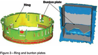
Thembelani 2 Shaft survey department currently has a standard report in place that reflects the sag or lift by elevating the set of six bunton plates cast into the concrete lining of the shaft at a vertical spacing of 6 m per ring or lift (Figure 3). This is done from the stage by means of a dumpy level (attached to a bracket that is affixed to the shaft sidewall to eliminate movement) and five shaft tapes suspended from the tape brackets in the shaft to determine the collimation and eventual elevation of the bunton plates. This report is then sent to Anglo American Mining and Technology department for analysis. This allows them to identify bunton plates that have deviated from the required elevation and make provision for additional spacers or to engineer structures in advance of the shaft equipping phase. This is done to eliminate or reduce costly standing time.
Concerns leading to the decision to carry out a 3D laser can
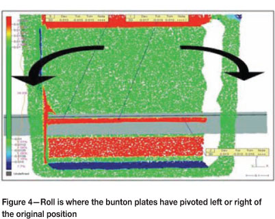
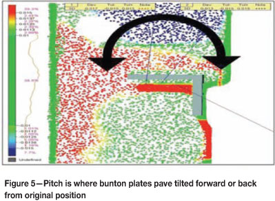
Although the survey report indicates an accurate representation of the sag or lift encountered, concerns were raised regarding the final positions and deviations such as pitch or roll of the Bunton plates (Figures 4 and 5), which is virtually impossible to survey manually during the sinking cycle due to time constraints. Should the bunton plates be out of position or a deviation such as pitching or rolling exists and it is not recorded before shaft equipping begins, the results could have a major impact on the cost of the project due to the standing time needed to take corrective action.
The ideal situation would exist whereby a survey within a vertical shaft could be carried out safely and in the least amount of time. The survey would indicate x, y, and z coordinate values of all bunton plates at any specific point required without adversely influencing the blasting cycle.
The solution would be to carry out a 3D scan of the vertical shaft using a laser scanner.
Most applications for scanning involve using the instrumentation in conjunction with other methods of surveying such as GPS and total stations. For the projects at Thembelani Mine, targets were geo-referenced in position prior to scanning; the scanning team then surveyed the areas of interest and positioned the scans during post-processing. A team surveyed a network of targets, first using a total station and secondly using laser scanner. During the 3D survey the geo-referenced targets were recognized by the software, which distinguishes the targets from the rest of the data in the scan. This methodology was used to register scans in all aspects of laser scanning. By combining the geo-referenced target locations with the targets picked up in the scans, it was possible to compare the accuracies of the target-to-target registration against the total station coordinates. The complete dataset could then be used to create a 3D meshed model of the development, allowing compatibility with CAD packages used by the mine.
Methodology
As such a project had not yet been attempted, Anglo American Platinum worked closely with 3D Mine Surveying International in developing the most suitable procedures for carrying out a trial scan. The requirement was to identify the time needed to do the scan and any other issues for consideration should the decision be made to scan the complete shaft.
To ensure that the survey was carried out to a high level of accuracy, as required by the engineers working on the project, a stop-and-go system was developed. This was to ensure the scanner remained locked in a stationary position while the instrument carried out a scan. Any movement in the scanner position would have compromised the integrity of the data. As such, scanning and surveying from the stage or kibble was not an option. A specially designed bracket was manufactured to allow the scanner to be fixed to the nut-boxes cast into the concrete lining of the shaft. Anglo American Platinum conducted a test within the shaft using poles of 3.5 m, 3.0 m, and 2.8 m to pre-determine the optimum position before manufacturing the bracket. It was noted that the optimal length would be 2.8 m, as this had neither an effect on the detail recorded nor on the angle of incidence to the targets during the trial. The best position to attach the bracket without fouling was the cast-in nut-boxes to be used for the future Mary-Anne cage.
The bracket could be manoeuvred and attached in position from the safety of the stage, which was then lowered prior to the scan being carried out. (Lowering the stage removed it from the view of the scanner, thus maximizing the level of detail picked up by the instrument.) By installing survey targets from an existing Weisbach survey base installed in a station or level break-away, using a total station, the scanner could now be geo-referenced into the local survey network and used to link each of the six scans.
Improved procedures when performing scan of a vertical shaft
Traditional methods of elevating the set of six bunton plates cast into the concrete lining of the shaft by means of a dumpy level take approximately 1 to 2 hours to complete, with limited information obtained. The trial scan took approximately 20 minutes to complete, and the optimized time is envisaged at 7 minutes. During this time, vast amounts of data can be captured, not only pertaining to the bunton plates, but including information regarding shaft alignment.
Bunton plate deliverables
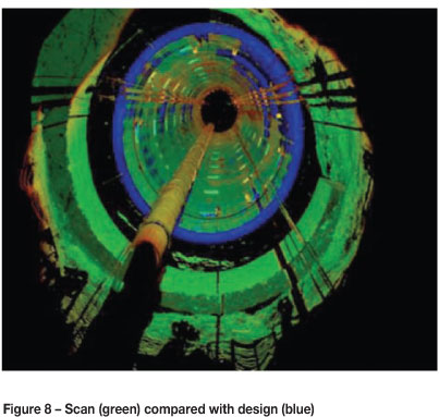
To identify vertical and horizontal deviations from the CAD model of the bunton plates, the geo-referenced CAD model was superimposed on the as-built point cloud (scan). From this, comparisons could be made and analysed for roll or pitch and corrective action (Figures 4 and 5). Corrective action could be aimed either at the addition of spacers (sag) or modifying the structure (lift).
Shaft alignment deliverables
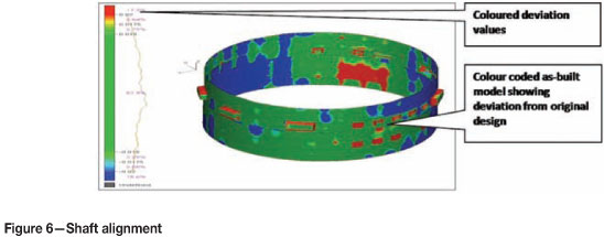
To ascertain the deviation between the CAD model and the as-built design, a heat map approach was used to highlight potential problem areas. The tolerance was set to 15 mm deviation either side of the design (with red being smaller and blue being bigger). Red and blue highlight the problem areas, and green indicates the optimum (Figure 6).
Additional benefits of performing a 3D scan in a vertical shaft
The 3D data can be used as a reference dataset for future surveys of the shaft. By fitting permanent targets to the shaft, any future surveys can be checked against the original network to identify changes over time.
Future redesigns and retrofitting of equipment
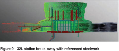
By having an accurate 3D model of the as-built shaft, any future upgrades or modifications to the structure can be made with reference to the original model rather than the design model, which may deviate slightly. Figure 9 reflects a cross-section of the 32 Level shaft station breakaway with the steelwork referenced in.
Advantages and benefits of carrying out laser scanning in development ends
When drawing comparisons between total station surveying and laser scanning, the most apparent difference is the cost of the instruments and accompanying software. Laser scanners may be up to 15 times more expensive than a mid-range total station. All things considered, it would be easy to disregard laser scanning as being too expensive, if it were not for the cost benefits that can be realized from using the technology.
If laser scanning is to be readily accepted as a common form of surveying for underground mining, it is important that traditional information obtained using a total station (or similar instrumentation) be generated just as easily from 3D data. By using a single combined dataset it is possible to revisit the data, extract information for specific applications/reasons, thus minimizing the need to return underground to obtain additional information on a job-specific basis.
One of the most time-consuming tasks for a surveyor is sectioning, where a total station is used to provide a slice of a tunnel profile at a specified position. Traditionally, a total station is set up in the middle of a drive perpendicular to the sidewall, and locked in a horizontal plane. The instrument then rotates through a vertical alignment taking a distance reading at intervals set by the surveyor. This task takes some time, potentially holding up tramming in that drive. If several sections need to be created, there is the potential for significant disruption to tramming and other operations in that part of the mine.
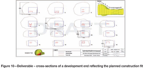
Using 3D data the acquisition time for tunnel sectioning is reduced to 3.5 minutes per scan. Once the survey is completed the scans can be registered together off-site without impeding other operations. After the data set has been compiled, it is relatively straightforward to extract the sections or other information that is required by others concerned. An entire drive can be sectioned at any interval the surveyor requires at the click of a button. Figure 10 shows an 8 m section of a decline split into 15 individual sections at 0.5 m intervals. It took less time to create 1000 sections from the 3D data than it took to create five sections captured and drawn using traditional techniques.
The use of total stations remains vitally important for survey control, but the need for frequent return visits for small detailed sections is eliminated with scan data. A typical laser scanner captures more than 50 000 points a second with an average scan time of 3.5 minutes. In contrast, a surveyor would be able to capture 500 points in a shift (4 hours). When surveying on projects within confined workings, the surveyor is given narrow windows of opportunity to carry out vital surveys for the development of the project. To geo-reference the scans, targets are fixed to the sidewall of the drive. These targets can be surveyed into the mine's network during maintenance periods or off-weekends using traditional total station survey methods.
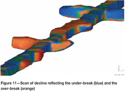
There are many other tasks that can be performed using the 3D data that could not practically be carried out or obtained using a total station or theodolite. Analysing the 3D data to compare the original 3D design against the actual model can identify and quantify areas of over-break and under-break. These can be easily interrogated for volumes. With the volumes, a cost and method can be assigned to the removal and sliping of material during re-engineering (Figure 11).
How laser scanning would add value from the beginning of a project
By creating a 3D model of a project as it develops, an accurate analysis can be conducted by comparing and contrasting the as-built structure against the original design. Any deviation from the original design will be obvious from a visual perspective, as well as providing the survey team with the advantage of being able to interrogate the numerical data used to build the 3D model. Any deviation from the original design can be identified within hours, allowing corrections to be made within a working shift. By building a 3D plan of the development, a model can be used by teams of engineers and planners in the office to investigate specific details of the mine. This will allow them to determine whether structures like conveyors, monorails, pipes, and other services will fit as planned.
Benefits that can be realized by other departments/disciplines
The real benefit of laser scanning is apparent when continuous analysis of data is required. The rich laser scan datasets can be revised and worked on continuously off-site by different departments and teams for a multitude of applications, ranging from rock engineering, geology, and ventilation to planning, design, engineering, and safety.
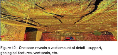
The 3D data exported from the scanning software is directly compatible with mine development and design software such as MicrostationTM, SurpacTM, DatamineTM, MicromineTM, VulcanTM and others. This allows the different departments to view and analyse information specific to their needs (Figure 12).
Rock engineering can also benefit in mines where seismicity is problematic. Repeated scanning can identify movement and rock deformation, helping to identify areas that may have become unstable over time, and details such as support and meshing can be captured and geo-referenced to millimetre accuracy with every scan.
Geology can also benefit by scans of the rock-mass structure before shotcrete has been applied. A permanent map of the structure is logged, allowing the information to be revisited throughout the life of the mine. Exact shotcrete thickness and quality can be determined by comparing before and after scans of the rock mass.
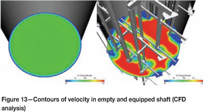
Ventilation can benefit by using 3D data for computational fluid dynamics (CFD). Analysis of ventilation in underground mines can be improved by quantifying how changes in design, layout of infrastructure, and fleet management impact on a mine's ventilation network and airflow within a mine (Figure 13).
Capturing laser scan data is less intrusive on the development due to the volume of information that can be captured over a short period of time, minimizing the delay to other teams that may need to access the same working area. For more complex analysis, CAD models of engineering structures can be combined with an as-built 3D model of the mine to show a true representation of what the mine will look like before the costly process of installation is undertaken.
Accident scene investigations
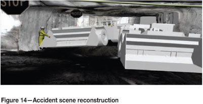
In the event of an accident, where a laser scan survey has previously been carried out, the area can be re-scanned for an intricate comparison of the area before and after the incident. This provides investigation teams with access to a rich source of information that is invaluable for accident investigation and analysis. The incident can be reconstructed and the sequence of events determined, revealing the exact cause of the incident and providing learning material from such cases in a drive to eliminate repeat incidents. This information can also be reproduced in animations, providing an excellent tool for safety training and on-site induction, based on site-specific virtual reality models (Figure 14).
Conclusion
Traditional surveying gathers limited data in most environments, which may impact on accuracies in material estimations and engineering plans. Laser scanning has the ability to minimize these errors, as it generates millions of data points gathered from the real surface composition. These in turn are translated into accurate models for planning and calculation. The time saved in being able to correct any possible errors before infrastructure installation far outweighs the costs of conducting a laser scan survey. By capturing such a vast amount of data, critical information that may have been overlooked by a surveyor using a total station to capture a few discrete points is captured by default. As more experience is gained with scanning, so too will the accuracy, pushing the technology towards levels that are acceptable for check surveys and giving scanners autonomy from traditional total station control.
The most important milestone in the advance of using laser scanning in underground mining is the ability to gather and produce information currently required by the different departments within a mine. The technology will gain acceptance by the industry if information can be captured faster with less intrusion on production and development. In addition, if laser scanning is able provide information critical to reducing costs and provide solutions to identified problems, this too will promote its acceptance. It is therefore important to identify ways in which other departments can benefit from this source of information. By raising the awareness in the applications of laser scanning in underground mining, the value and benefits to an overall operation will also increase.
Geotechnical engineers and ventilation teams are starting to use 3D data in software packages such as SplitFX (Split Engineering, 2010) and Ventsim (Ventsim, 2010) to bring a 3D element to those disciplines. As computer power and networking becomes easier, it will allow surveyors to be the custodians of this data source, ensuring the integrity and accuracy of the information on the mine's database. This information can be accessed by all departments and processed and analysed as and when it is needed. Many software packages used for mining operations are already compatible with the file formats created from the 3D laser scan data. This familiar platform will help with the integration of laser scanning into modern mining.
Summary of the applications and benefits of 3D scanning in the mining industry
Improved safety
Minimizes the amount of time personnel have to spend in high-risk areas
Health and safety
Improved efficiency
Improved ventilation
Rock engineering / geology
Quality assurance and quality control
Acknowledgements
The authors gratefully acknowledge the permission of Anglo American Platinum Limited to publish this work. They further acknowledge the contributions of Michael Livingstone-Blevins and Dr James Jobling-Pursor for their assistance and consultation in the development of the laser scanning project at Anglo American Platinum's Thembelani Mine.
Bibliography
Adami, A., Guerra, F., and Vernier, P. 2007. Laser scanner and architectural accuracy. Proceedings of 21st International CIPA Symposium,, 1-6 October 2007, Athens, Greece. [ Links ]
Berenyi, A., Lovas, T., and Barsi, A. 2010. Terrestrial laser scanning - civil engineering applications. International Archives of Photogrammetry, Remote Sensing and Spatial Information Sciences, vol. 38, no. 5. Commission V Symposium, Newcastle-upon-Tyne, UK.
Brown, S.E. 2003. 3-D laser scanning for smoother offshore retrofits exploration and production. The Oil & Gas review 2003, Exploration and Production. Tuch Group plc, London. [ Links ]
Jobling-Purser, J. 2011. Path to 3D Project. 3D Mine Surveying International Ltd. Project proposal for Anglo American plc. [ Links ]
Jobling-Purser, J. and Scott, J. 2012. Using 3D data for computational fluid dynamics (CFD) vent analysis in underground mines. [ Links ]
Pagounis, V., Tsakiri, M., Palaskas, S., Biza, B., and Zaloumi, Z. 2006. 3D laser scanning for road safety and accident reconstruction. Proceedings of the 23rd FIG Congress, Munich, Germany, 8-13 October 2006. [ Links ]
Split Engineering. Split-FX software. http://www.spliteng.com/split-fX/ [Accessed July 2010] [ Links ].
Stone, G.S., Lipman, W.C., Witzgall, R.R., and Bernal, C. Laser scanning for construction metrology. Proceedings of the American Nuclear Society 9th International Topical Meeting on Robotics and Remote Systems, Seattle, Washington, 4-8 March 2001. Paper no. 082. American Nuclear Society, LaGrange Park, IL. [ Links ]
Van der Merwe, J.W. Date. An examination of the applications and benefits of using 3D laser scanning for surveying and modelling vertical mine shafts and underground development operations. Proceedings of the Anglo American Young Mining Professionals Conference, Johannesburg, South Africa.
Ventsim Software. http://www.ventsim.com/ [Accessed July 2010] [ Links ].
© The Southern African Institute of Mining and Metallurgy, 2013.
ISSN 2225-6253. This paper was first presented at the 5th International Platinum Conference 2012, 18-20 September 2012, Sun City, South Africa.

