


Serviços Personalizados
Artigo
 Inglês (pdf)
 Artigo em XML
 Referências do artigo
Indicadores

Links relacionados
-
 Citado por Google
 -
 Similares em Google
Compartilhar

 Permalink
Journal of the Southern African Institute of Mining and Metallurgy
versão On-line ISSN 2411-9717
versão impressa ISSN 2225-6253
J. S. Afr. Inst. Min. Metall. vol.112 no.8 Johannesburg Jan. 2012
JOURNAL PAPER
Origins of some fractures around tabular stopes in deep South African mines
G. van AswegenI; M. StanderII
IInstitute of Mine Seismology, Stellenbosch
IIOpen House Management Solutions, Potchefstroom
SYNOPSIS
The geometry and morphology of a set of low-angle fractures around a stope in a deep Witwatersrand gold mine are explained in terms of extension fractures forming under variable conditions of stress. Primary extension fractures (E1) form some distance ahead of an advancing stope along the σι, σ2 plane. With stope advance, a couple of these fractures end up in a stress regime conducive to transpressional shear and a secondary set of extension fractures (E2) is formed at a high angle to the primary fractures. i.e. at a low angle to the stope. As the E2 fractures are undermined, they migrate into a stress regime of transtensional shear and a third set of extension fractures (E3) may develop between E2 fractures. These have sigmoidal shapes, being parallel to the E2 fractures at the E2 discontinuity where σ3 is negative, and curved through the un-fractured rock between E2 fractures where σ3 is positive at the instant of fracturing.
The fractures all display fractographic features characteristic of dynamic extension failure with striae indicative of the direction of rupture propagation and the local, instantaneous orientation of σ1.
Keywords: fracturing, extension fractures, low-angle fractures, fracture classification.
Introduction
We describe some observations and interpretations of fractures associated with deep, tabular stopes in gold mines of the Witwatersrand Supergroup (Wits) and note similarities to some fractures in the Bushveld Complex platinum mines. We briefly cover the popular nomenclature of the fractures and focus on the genesis of a set of flat-dipping fractures that pose roof stability problems in many stopes.
The salient features of these ore deposits are described in numerous texts, and are conveniently summarized for the rock mechanics discipline in Ryder and Jager (2002).
Fracture nomenclature in Wits gold mines
Fractures around stopes in Wits gold mines have been studied in depth (pun intended), and a nomenclature has been established to describe these dominant mining-induced discontinuities. Although a new nomenclature is suggested by Jager and Ryder (1999), a diagram from a paper by Adams etal. (1981), reproduced here as Figure 1, has for long been a standard reference and is quoted frequently. Three fracture types were identified in this original paper, namely:
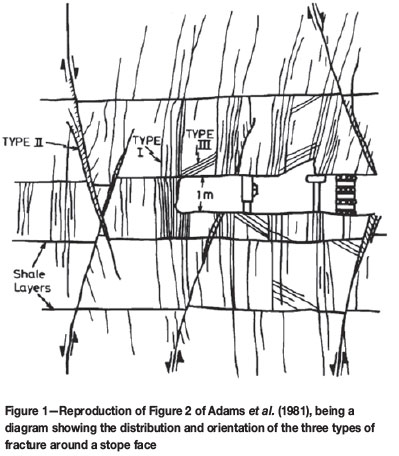
 Type /Extension fractures that follow the σ1 trajectories around the stope
Type //Shear fractures along the planes of maximum ESS ahead of the stope face
Type ///Low-angle and vertical, younger fractures.
Note that Figure 1 does not refer to bedding-parallel fractures or bedding-parallel shears, which were documented, for example, by Brummer (1987).
We focus mainly on the Type III fractures and quote their description directly from the original text: 'Type 3 fractures form close to the stope face within rock which already contains Type 1 and Type 2 fractures. They are a later generation of fractures, caused by a localized, secondary fracture process. Thus they are superimposed on to the more regional fracture pattern which is developed several metres ahead of the face. The fractures do not occur throughout the stope but develop preferentially in rock which is not initially highly fractured. They have planar surfaces and do not reveal any movement across the fracture plane. The fractures are symmetrically disposed around the reef plane, in the hangingwall they dip at 30 to 40 degrees in the direction of face advance and in the footwall dip against the direction of face advance. They do not extend more than 3 m into the hangingwall or footwall and seldom have a strike length greater than 5 m ... The distribution and orientation of Type 3 fractures suggests that their formation is closely associated with the shape and proximity of the stope face'.
In the handbook of Jager and Ryder (1999), a new classification system for fractures around a stope is presented:
1. Shear fractures. The description in the handbook suggests that some of the shear fractures are of dynamic origin, which would make them Ortlepp shears (van Aswegen, 2005) while the majority develop 'without the emission of significant seismic energy' and are thus considered to have evolved as the accumulation of a large number of small displacements. How this is proven either way is not explained.
2. Extension fractures.
a. Near-vertical, primary extension fractures that develop some distance ahead of the advancing mining face. At least 2 m ahead of the face was measured (Adams and Jager, 1980), while the sketch in the handbook (Figure 4.2.5) suggests a greater distance
b. Secondary extension fractures that develop close to the face, between the face and primary extension fractures. They are vertical ahead of the face, but dip around 70° in the hanging- and footwalls.
3. Low-inclination fractures. These are generally referred to as 'low-angle fractures'. Again we quote verbatim: dipping 20° to 40° towards the face in the hangingwall. These young fractures develop primarily close to the stope face where intact 'hard patch' bands of rock are preserved at the stope face, and follow the σ1/σ2 plane that would be expected under those circumstances. They usually occur sporadically in patches elongated in the dip direction and measure a few metres in length. They terminate against steep-dipping fractures indicating the relative time of their development. . An unusual development of this type of fracture has been noted at a number of rockburst sites, where fractures of this nature emanate from the top corner of the face and extend 5 m or so up and back into the hangingwall. The length along the stope of some of these is more than 40 m. They are characterised by a peculiar fracture surface comprised of curved interlocking fragments about 10-20 mm thick and 100-150 mm long. It is assumed that they formed as a result of dynamic loading'.
4. Fractures formed in the plane of the stratification. (See Brummer, 1987). It is interesting to note that neither Adams et al. nor Jager and Ryder refer to the low-angle fractures specifically as extension fractures.
Observations
Our curiosity about the origin of the low-angle fractures was triggered by their importance for hangingwall stability. In this section we describe observations that led to our interpretation of their origin.
Pseudo cross-bedding
A seemingly unrelated phenomenon is briefly described here since it turns out to be relevant in the full analysis of fractures around stopes. We refer to it as pseudo crossbedding, illustrated in Figure 2. It is a set of closely-spaced discontinuities within a quartzite band with geometry similar to that of cross-bedding. The discontinuities differ from cross-bedding in that their orientations asymptotically approach both the top and the bottom of the layer. In true cross-bedding the cross beds merge asymptotically with the bottom of the layer' while at the top they end at a high angle to the bedding. The fabric in the quartzite band is also similar to s-c fabrics found in ductile shear zones. This phenomenon and its relevance to low-angle fractures is further discussed in the following sections.
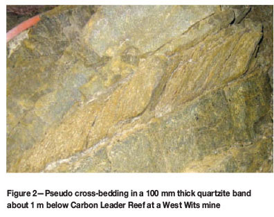
The particular example shown in Figure 2 is from about a metre below the Carbon Leader Reef at a mine near Carletonville, where it is exposed in a dip gully some distance in the back. The quartzite band with the fractures is about 100 mm thick.
Fractures in stopes
During frequent investigations of fall of ground incidents in stopes on both the Carbon Leader Reef horizon as well as the Ventersdorp Contact Reef horizon, we noted keyblock failures as predicted by the combination of primary extension fractures and low-angle fractures as shown in Figure 1.
We noted not only the age relationship between the low-angle fractures and the primary extension fractures as described Jager and Ryder (1999), but a specific spatial relationship the low-angle fractures generally occur in the 'hard patches' between the primary fractures and at a high angle to the primary fractures (Figure 3).
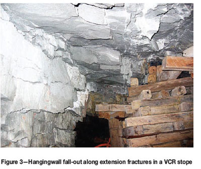
A pronounced linear fabric or striae on the surfaces of both sets of fractures observed in places was recognized as fractographic features typical of extension fractures (Bahat et al., 1995). In some cases, classic mirror zones with fringes are visible, but generally only striae with variable degrees of divergence.
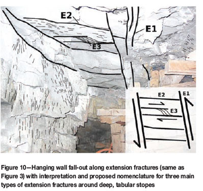
A particular example is shown in Figure 3 which is a photograph of hangingwall exposed after key-block failure some 2 m deep in a westerly advancing stope along the VCR ore body in the West Wits mining district, approximately 3300 m below surface. Because of the depth of failure, the primary and low-angle fractures are well exposed. The fall was not associated with a particular seismic event, although during the 6 months period up to the time the photograph was taken hundreds of very small and several small seismic events, up to moment magnitude 1.5, were recorded in the immediate surrounds.
Basic background regarding extension fractures and shears
To interpret our observations we had to revisit the fundamentals of extension fractures and shears.
Extension fractures and stress
There is no need to remind rock mechanics practitioners that extension fractures occur along the σ1, σ2 plane (Stacey, 1981). It may, however, not always be appreciated that extension fractures as we observe them some time after formation (anything from hours in mines to billions of years in the geological world) are a useful reminder of what the orientation of stress was at the place and the instance of the fracture occurrence. In mines, where stress changes occur orders of magnitude faster than in nature, extension fractures are generally of dynamic origin. The stress orientation in the surrounding rock does not change during the formation of the fracture. It may do so soon afterwards due to the presence of the new weakness, but the orientation of the fracture is a snapshot of the trace of σ1 at origin time. And we see that this holds true where extension fractures are arranged in bow-wave formation around developing excavations.
We note, of course, that the extension fractures of concern here can and do occur under triaxial stress conditions provided σ3 is relatively small and the rock brittle (or the loading fast).
Fractographic and kinematic indicators
Characteristics of extension fractures include fractographic features such as mirror zones and hackles (see Bahat et al., 1995, Sagy et al., 2006). The main source of corrugations along a newly forming fracture surface is the instability when the energy flux into the fracture tip becomes too high to be accommodated by a single fracture surface, and branching occurs (Sharan et al., 1996). It is like a speed wobble that inhibits extreme rupture velocities. Ortlepp (1997) shows striking examples of mirror zones and notes that they are often associated with strain bursting in the Klerksdorp gold mining district.
The striations on extension fractures should not be confused with slickensides, which are kinematic indicators of slip (Doblas, 1998) and are used routinely to judge the sense and direction of fault slip by geologists or the direction of sidewall ejection by rock mechanics practitioners. In the case of the primary extension fractures (E1 in our nomenclature described below, Type I according to Adams et al., 1981) the distinction does become blurred in places, since by the time the fracture zone is exposed in the stope it may have undergone some shear displacement. The fractographic striae on an extension fracture map the direction of rupture propagation which, in general, is parallel to σ1. When the eventual shear slip takes place under nearly the same prevailing stress conditions, the slickensides mark the direction of slip, which is again parallel to σ1 (being parallel to the intersection line of the slip surface and the plane containing σ1 and σ3). The two sets of linear features can thus become mixed up. One distinguishing feature of the fracture striae is the tendency to fan out away from the point of rupture initiation, while generally slickensides remain parallel and straight over long distances. We note that extreme fanning, like that beyond the rim of a mirror zone, is associated with deceleration and eventual stoppage of the rupture - enough new surfaces have been created to accommodate the fracture energy.
Shear zones
Because simple shear yields volume-constant plane strain (e.g. Ramsay, 1967, Chapter 3-4.3) and because rock has limited compressibility, rock generally tends to deform in shearit is simply the easiest way for rock to deform. Because rock is weakest in tension it tends to fail in tension. This all comes together nicely in the standard sketch of the characteristics of a shear zone found in geological texts. Some geology texts show complicated schematics to illustrate all the different structural features that can and do develop in shear zones of different sizes, from microscopic scale to continental scale and in laboratories (e.g. Wibberley et al., 2000). They deal with large to extreme finite strain and the sub-structures span the repertoire of rock deformation phenomena. Here we are interested in infinitesimal strain and need to understand only the geometric relations between shear zones and extension fractures. Since, however, features like those in Figure 2 may be reminiscent of Riedel shears we provide a schematic explanation of both in Figure 4.
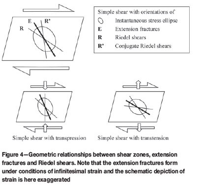
Note that Figure 4 is a schematic presentation reflecting the orientations of features within zones of infinitesimal shear strain. It is purely illustrative, and the amount of strain suggested by the schematic shear boxes and the strain ellipses is grossly exaggerated. Until the moment of the formation of the extension fractures there is no finite volume change or strain beyond the elastic strength limits. That also means that we refer here to infinitesimal transpression and transtension. Via constant elastic moduli, infinitesimal strain is equivalent to stress.
In order to address the origin of the fabric in Figure 2, we consider the internal characteristics of shear zones. In ductile shear zones, where finite strain is large, the S-fabric defined by platy minerals and smeared-out grains has the same geometry as the fabric inside the brittle quartzite band of Figure 2. From their brief description it appears that Sellers et al. (1998) did, indeed, interpret such a fabric as a shear fabric (s-c fabric). Note that s-c fabrics are characteristic of ductile shear zones, not the brittle environment of Witwatersrand gold mining. Furthermore, the shear motion required to form them in the hangingwall of an advancing stope the way it is depicted in Figure 3 in Sellers et al. would be opposite to that induced by the local stress orientations. We explain below that the Figure 2 feature is not a ductile fabric.
The geometric relations between extension fractures within shear zones in the brittle domain are specifically addressed by Ramsey and Huber (1983), who show photographs of en-echelon extension gashes to demonstrate the natural occurrence of the fracture orientations predicted in their Figure 3.21, part of which is reproduced here as Figure 5. Specifically, we note that the angle between the extension fracture and the shear zone walls are large when formed under transpressional load and small when formed under transtensional load.
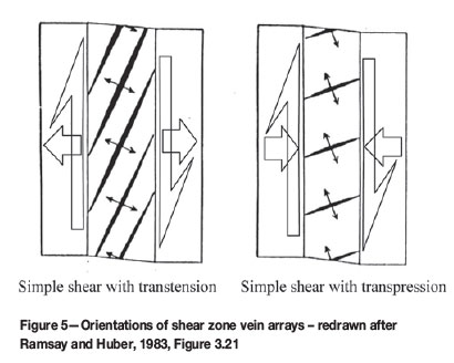
If one considers a shear zone within which the degree of transtension or transpression varies across the shear zone, we have a simple theory for the development of curved extension fractures as the origin of the fabric in Figure 2. We also note that in the Figure 3.22A of Ramsey and Huber (1983), which is a photograph of natural extension fractures in a transtensional shear zone, the curvature of the extension fractures show the same tendency as do the discontinuities making up the fabric in Figure 2.
Note that we consider the orientations of extension fractures as 'mappings' of the stress trajectories at the instant of fracturing, excluding the effects of subsequent rotation. With moderate continuous shear strain the extension fractures do, of course, rotate relative to the instantaneous stress field and become shear surfaces themselves (note our comment on shear fabrics intermixed with fractographic fabrics in the previous section) such that the bulk of substructures within an evolved brittle shear zone may be referred to as Riedel shears (e.g. Katz et al., 2004). The beams between the extension fractures of Figure 5 then become subjected to shear strain and a secondary set of extension fractures may develop. In principle there need be no end to this repetition of sub-structures. King and Sammis (1992) in fact elegantly describe this as the mechanism of finite brittle strain.
Stress trajectories through zones of variable elastic shear strain
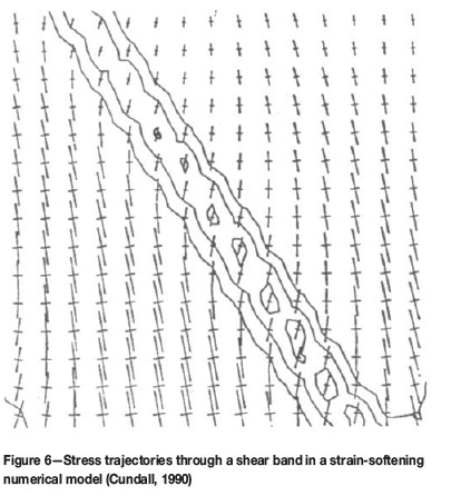
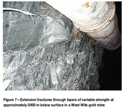
As shown in Figure 4, the orientation of σ1 within a shear zone (in the domain of infinitesimal stain) depends on the degree of transpression or transtension applied to the shear zone. In a static stress field with zones of rock with variable elastic shear moduli (e.g. different stratigraphic layers) and a stress load not perfectly orthogonal to the banding, one would expect bending of the stress trajectories. This is because the magnitude of elastic shear strain varies from layer to layer as a function of their respective shear moduli and thus the orientations of the stress vary. This is, for example, illustrated in a numerical model by Cundall (1990). His Figure 9 is here reproduced as Figure 6. In Figure 7 we show a set of bow-wave extension fractures with orientation deflections cutting through different arenaceous layers in a tunnel approximately 3000 m below surface at a West Wits mine.
Origin of low-angle fractures around stopes
With the somewhat exhaustive treatment of shear zones and extension fractions as background, we now propose the origin of the low-angle fractures. They are extension fractures in transpressional brittle shears formed between sets of primary extension fractures. We recognise three main sets of extension fractures and propose a new nomenclature namely, E1 to E3, and see their development as follows:
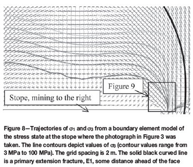
A primary extension fracture E1 ('Type I') forms some distance ahead of the face along the σ1 traces (Figure 8)
In following mining steps, new E1 fractures are formed in the same place relative to the stope face, i.e. the old ones 'migrate' closer to the stope
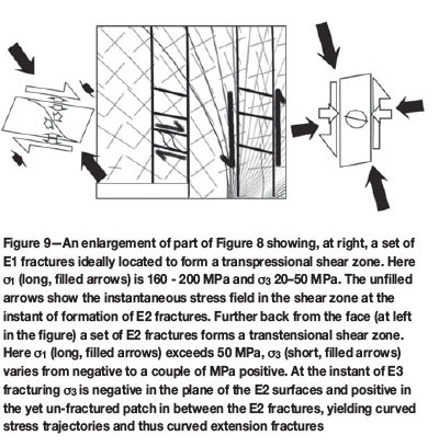
Where a set of E1 fractures ends up close to the stope, the stress field creates a transpressional shear zone and E2 fractures (low-angle fractures, 'Type III') develop at high angles to the shear zone walls (Figure 9). Note that in this environment the orientation of the new E2 extension fractures do not 'follow the σ1/σ2 plane that would be expected under those circumstances' because that would imply that they develop only behind the face. In terms of our model, they rather form in an area where the general σ1/σ2 plane is still at a relatively high dip. The E2 fractures follow the σ1/σ2 plane created instantaneously during a sudden increment in shear strain within the shear zone defined by the E1 fractures. Such a sudden increment would most likely be associated with a production blast allowing sudden stope closure to help invoke the shear couple shown in in the right hand side of Figure 9
By the time the E2 fractures are undermined, shear loading allows the development of E3 extension fractures between E2 fractures in a similar way to which the E2 fractures developed between E1 fractures. There is an important difference, though. In this environment, the shear loading on the E2 system is transtensional. Along the plane of E2 fractures the normal stress is close to zero or even negative. Any new extension fractures developing here would simply be the opening up of the existing E2 fracture. In the yet unfractured beam between two E2 fractures, however, the minimum principal stress will be greater than zero and the stress trajectories will thus curve from an orientation parallel to the E2 fractures to an orientation at an angle to the E2 fractures, as illustrated on the left of Figure 9.
E3 fractures are rare and 'new' in the sense that they are not recognized in the classifications of either Adams et al. or Jager and Ryder, described earlier.
Figure 10 shows this interpretation applied to the fractures of Figure 3 and it depicts the proposed simple numbering system for extension fractures around tabular stopes. There will, of course, be numerous other extension fractures that develop under different stress conditions and in the presence of numerous other discontinuities, but the scheme proposed in Figure 10 probably captures the main ones.
In the case of our Figure 2, the same mechanism as that described for the E3 structures above apply, except that the bedding planes took the place of the E2 fractures. The quartzite layer with the E3 type fractures was clearly weaker than the layers above and below. We have noted curved extension fractures through layers of variable strength in South African gold mines in several places, e.g. where the Green Bar is exposed above the Carbon Leader Reef. To our knowledge, however, such curved extensions fractures have not been formally described or explained before.
Examples from the Bushveld Complex
We include two photographs from platinum mines in the western Bushveld Complex showing sets of low-angle fractures of seemingly the same origin as the E2 fractures described above.
The first photograph is from the Rustenburg area (Figure 11, top). Here a local pillar burst (case 4 described by Malovichko et al., 2012) caused dynamic closure in the direction normal to the stope and key-block shakedown some 15 m further along strike in the back area, locally exposing the hangingwall fracture geometry. The moment tensor solution of the pillar failure shows reef-normal dynamic closure. In a numerical model that includes the locally-used high k-ratio, the same deformation mechanism is reflected with a modelled moment tensor very close to the observed. This suggests that the local stress concentrations yield failure mechanisms driven by the mining-induced (near-vertical) stress similar to the case around deep-level stopes in the gold mines.
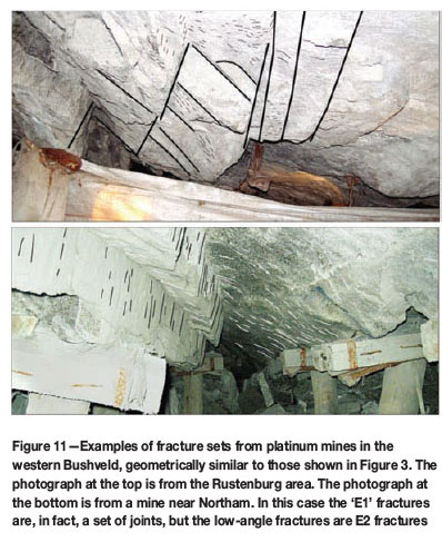
The second photograph was taken in 2006 in a mine in the northern part of the western Bushveld Complex. In this case a remnant was being mined and a relatively small seismic event was associated with some dynamic stope closure and significant shakedown damage, exposing the hangingwall to a height of at least a metre. A dominant joint set sub-parallel to the face appears to have acted as the 'El' fractures in this case, and the striae on them were mainly slickensides from keyblock failure. The striae along the low-angle fractures (E2) did not, however, have the appearance of slickensides.
Conclusions
We present a mechanism that may account for the majority of low-angle stress fractures (E2) around stopes in Wits gold mines and possibly also in some cases in western Bushveld Complex platinum mines. The mechanism is one of extension fracturing in transpressional shear zones formed when primary extension fractures (El) end up in the appropriate stress field close to the stope. The E2 fractures are oriented at a high angle to the El fractures and thus at a low angle to the stope. Rarely, the process repeats itself when the E2 fractures constitute shear zones in the hangingwall, to form E3 extension fractures (not observed in the platinum mines yet). Here the shear load is transtensional with the normal load near zero along the E2 fractures, but higher within the non-fractured bands between the E2 fractures. This causes curved stress trajectories and thus the E3 fractures are sigmoidaly shaped.
We note that all the example cases referred to above are from seismically active areas, thus in relatively high-stress environments where the mining-induced stress around the stope face is the main driver of fracture patterns.
Acknowledgements
We thank our colleagues and friends at AngloGold Ashanti who spent many hours with us crawling through broken stopes in search of interesting phenomena. The material was originally presented at the SANIRE2010 symposium organized by the North West branch of SANIRE at the Village Club, Western Levels, October 2010 (see http://www.sanire.co.za/component/docman/cat_view/64-proceedings/120-symposium-2010. We thank the North West branch for permission to publish the paper.
The review process provided very constructive feedback which helped to improve the manuscript significantly.
References
Adams. G.R. and Jager, A.J. 1980. Petroscopic observations of rock fracturing ahead of stope faces in deep-level gold mines. Journal of the Southern African Institute of Mining and Metallurgy, vol. 80, no. 6. pp. 204-209. [ Links ]
Adams, G.R., Jager, A.J., and Roering, C. 1981. Investigations of rock fractures around deep level gold mine stopes. Rock Mechanics from Research to Application. Proceedings of the 22nd US Symposium on Rock Mechanics, Cambridge, MA, 29 June-2 July, 1981. Einstein, H.S. (comp.). Massachussetts Institute of Technology, Cambridge. pp. 227-236. [ Links ]
Bahat, D., Rabinovitch, A., and Frid, V. 2005. Tensile Fracturing in Rocks, Tectonofractographic and Electromagnetic Radiation Methods. Springer Verlag, Berlin. 570 pp. [ Links ]
Brummer, R.K. 1987. Fracturing and deformation at edges of tabular excavations: development of a numerical model describing such phenomena. PhD thesis, Rand Afrikaans university. 204 pp. [ Links ]
Cundall, P.A. 1990. Numerical modelling of jointed and faulted rock. Mechanics of Jointed and Faulted Rock. Rossmanith, H.P. (ed.). Balkema, Rotterdam. [ Links ]
Doblas, M. 1998. Slickenside kinematic indicators. Tectonophysics, vol. 295. pp. 187-197. [ Links ]
Jager, A.J. and Ryder, J.A. (eds.) 1999. A Handbook on Rock Engineering Practice for Tabular Hard Rock Mines. Safety in Mines Research Committee, Johannesburg. [ Links ]
Katz, Y., Weinberger, R., and Aydin, A. 2004. Geometry and kinematic evolution of Riedel shear structures, Capitol Reef National Park, utah. Journal of Structural Geology, vol. 26. pp. 491-501. [ Links ]
King, G.C.P. and Sammis, C.G. 1992. The mechanism of finite brittle strain. Pure and Applied Geophysics, vol. 138, no. 4. pp. 611-640. [ Links ]
Malovichko, D., van Aswegen, G., and Clark, R. 2012. Mechanisms of large seismic events in platinum mines of the Bushveld Complex (South Africa). Journal of the Southern African Institute of Mining and Metallurgy, vol. 112, no. 6.pp.419-429. [ Links ]
Ortlepp, W.D. 1997. Rock Fracture and Rockbursts an Illustrative Study. Monograph Series M9. South African Institute of Mining and Metallurgy, Johannesburg. [ Links ]
Ramsay, J.G. 1967. Folding and Fracturing of Rocks. McGraw-Hill, New York. 568 pp. [ Links ]
Ramsay, J.G. and Huber, M.I. 1983. The Techniques of Modern Structural Geology: Strain Analysis. Academic Press, New York. 307 pp. [ Links ]
Ryder, J.A. and Jager, A.J. 2002. A Textbook on Rock Mechanics for Tabular Hard Rock Mines.Safety in Mines Research Advisory Committee, Johannesburg. [ Links ]
Sagy, A., Cohen, G., Reches, Z., and Fineberg, J. 2006. Dynamic fracture of granular material under quasi-static loading. Journal of Geophysical Research, vol. 111, no. B04406. [ Links ]
Sharan, E., Gross, S.P., and Fineberg, J. 1996. Energy dissipation in dynamic fracture. Physical Review Letters, vol. 76, no. 12, pp. 2117-2120. [ Links ]
Sellers, E.J., Berlenbach, J., and Schweitzer, J. 1998. Fracturing around deep level stopes: Comparison of numerical simulation with underground observations. Mechanics of Jointed and Faulted Rock. Rossmanith, H.P. (ed.). Balkema, Rotterdam. [ Links ]
Stacey, T.R. 1981. A Simple Extension Strain Criterion for Fracture of Brittle Rock. International Journal of Rock Mechanics and Mining Sciences and Geomechanical Abstracts, vol. 18. pp. 469-474. [ Links ]
Van Aswegen, G. 2008. Ortlepp shears - dynamic brittle shears of South African gold mines. 1st Southern Hemisphere International Rock Mechanics Symposium, 16-19 September 2008, Perth, Western Australia. Potvin, Y (ed.). pp. 111-120. [ Links ]
Wibberley, C.A.J., Petit, J-P., and Rives, T. 2000. Micromechanics of shear rupture and the control of normal stress. Journal of Structural Geology, vol. 22. pp. 411-427. [ Links ]
© The Southern African /nstitute of Mining and Metallurgy, 2012./SSN2225-6253. This paper was first presented at the, Southern Hemisphere /nternational Rock Mechanics Symposium (SH/RMS) 2012, 15-17 May 2012, Sun City, South Africa.

