


Servicios Personalizados
Articulo
 Inglés (pdf)
 Articulo en XML
 Referencias del artículo
Indicadores

Links relacionados
-
 Citado por Google
 -
 Similares en Google
Compartir

 Permalink
Journal of the Southern African Institute of Mining and Metallurgy
versión On-line ISSN 2411-9717
versión impresa ISSN 2225-6253
J. S. Afr. Inst. Min. Metall. vol.112 no.8 Johannesburg ene. 2012
JOURNAL PAPER
Improved understanding of explosiverock interactions using the hybrid stress blasting model
E. SellersI; J. FurtneyII; I. OnederraIII; G. ChitomboIII
IAEL Mining Services, Johannesburg, South Africa
IIItasca Consulting Group, Minneapolis, MN, USA
IIISMI, University of Queensland, Brisbane, Australia
SYNOPSIS
Since 2001, the Hybrid Stress Blast Model (HSBM) project members have developed a software suite to model the complete blasting process from non-ideal detonation to muck pile formation. To preserve the physics and improve solution time, the breakage engine uses a combination of analytical models and 2D axisymmetric finite differences to model near-field crushing, coupled to 3D discrete lattice fracturing and distinct element numerical methods to model throw and muck pile development. The model has been validated by comparison with laboratory and field tests in kimberlite. Multiple blasthole simulations are used to demonstrate how changes to blasting parameters can influence downstream efficiencies. Case studies of wall control blasting show that the presplit design must balance the two opposing effects of increased damage with increased charge and decreasing attenuation of the seismic waves with decreasing charge. Modelling of decoupled explosives needs further development. Reducing the charge towards the back of the trim blast results in a much more significant decrease in back damage than altering the timing. The model demonstrates how separation along the weaker planes in a jointed rock can coarsen the fragmentation, leading to inefficient beneficiation, and extends the damage to a distance of at least twice the burden behind from the blasthole, severely compromising the wall stability.
Keywords: blasting, modelling, discrete element method.
Introduction
Blasting and rock engineering are complementary disciplines. Whereas blasting is focused on the removal of the rock within the excavation to facilitate production, rock engineers are required to support the excavation to ensure the short-term safety of the miners and maintain the viability of the mining company by protecting the long-term stability of the entire mine. Proper blast design can be used to facilitate the work of both the blasters and the rock engineers. Any reduction in damage to the excavation limits the overbreak and hence minimizes the material that must be removed, and at the same time prevents unravelling of the rock surrounding the excavation (Sellers, 2011). In both disciplines there is a need for the ability to predict the effect of blasting on the rock mass.
The realization of the importance of including the proper dynamic rock mechanics linked with accurate detonation physics into blast design software resulted in an international group of mining and explosive companies combining with the University of Queensland and Itasca Consulting Group to form a research group to develop the hybrid stress blasting model (HSBM). The term hybrid refers to the way that a combination of numerical methods is used to model the various blast processes. Once the model has been validated against realistic blasts, it can be applied with more confidence to modelling of unknown situations. For the HSBM project team, the validation process must answer two main questions. Firstly, can the outcome of the blast be predicted before the blaster pushes the firing button? Secondly, if changes need to be made to the design, can the model predict these changes accurately? Validation of the code to date has focused on breakage and fragmentation in laboratory-scale experiments and larger concrete cube blasts (Onderra et al., 2009, Sellers et al., 2009, Sellers et al., 2010, Furtney et al., 2011), with some shortcomings in terms of the induced particle velocities that required reduced strengths to match the experimental fracturing. Subsequent to changes to the model formulation, simulations of well-instrumented field tests in kimberlite have been carried out, and measured and predicted face velocities, peak particle velocities, and fragmentation agree remarkably well using very generic rock and blast input parameters (Sellers et al., 2012). That modelling is briefly described here as a background to demonstrate the model's capabilities.
Recent improvements in the analysis efficiency coupled with the good agreement with the field tests have permitted the modelling of larger-scale production blasts to provide the blaster with an understanding of the effect of changing blast parameters and the rock engineer with ability to predict back damage to improve the wall stability of large open pits. This paper concentrates on describing some situations that demonstrate how the numerical model has improved our understanding of the dynamics of rock fracturing and particle interactions during surface blasting processes, and shows how subtle changes in the blasting parameters can improve or compromise downstream beneficiation processes.
Model formulation
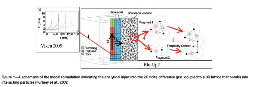
The HSBM project has extended over the past ten years, and has required a number of independent computer codes to be coupled together to achieve the project objectives of maintaining the physical processes and yet providing a model that is quick and robust enough to produce results for practical field application. The full details of the numerical code are complex and have required a number of papers for a complete description. A summary of these can be found in Furtney etal. (2009, 2011). For completeness, only a very brief summary of how the model is implemented is presented here. The relevant steps are shown schematically in Figure 1. Characterization of the explosive in terms of density, energy release, reaction extent, product equation of state (EoS), and velocity of detonation (VoD) is required as the first step of the modelling process to achieve a detailed pressure loading. These detonation aspects of the HSBM project are described in detail in Braithwaite and Sharpe (2009). A non-ideal detonation code, Vixen2009, a component of the HSBM software suite, determines these parameters using a semi-analytical approach and transfers them as inputs to the breakage engine (called Blo-Up2). The explosive is represented on a coarser scale as a special constitutive behaviour in the central zones of an axisymmetric continuum representation based on FLAC (Itasca, 2008). The axisymmetric approximation is used instead of a full three-dimensional approach to save computer time with the realization that the detonation-induced loading is essentially axisymmetric for the duration of the detonation. Instead of the fine grid, full detonation, fluid dynamics solution that takes weeks to run, a coarse grid programmed burn algorithm (Cundall and Detournay, 2008) is used to simulate the detonation process, and the expansion and axial flow of the detonation products (step 2) by releasing energy into coarse finite- difference zones representing explosive based on a predetermined velocity of detonation, calculated by Vixen2009. Beyond the central explosive zones a continuum Mohr-Coulomb material constitutive law represents the crushing and energy loss of the near-field rock (step 3).
The FLAC zones representing the explosive and near-field rock are coupled to a 3D lattice-type discrete element method (Furtney et al., 2009). This is a simplification of the standard DEM calculation (Potyondy and Cundall, 2004), which takes too long to solve and has functionality that is not needed for blast fracturing that is induced mainly by tensile stresses outside the compressive near-field zone. The lattice method applies forces to point masses, which have only translational degrees of freedom, and the connecting springs have a rate-dependent tensile breaking strength. The radial fracturing occurring away from the borehole (step 4) is primarily tensile-mode failure, which still is represented well with the lattice-model simplifications. The compromise entailed in this speed-up is the poor representation of shear wave transmission, though this can be included if desired. Lattice nodes that overlap FLAC zones are velocity-controlled by the movement in the FLAC zones. The lattice nodes then contribute forces back to the FLAC zones. This mechanism provides full coupling between the lattice region and the near-field representation.
The mechanical calculation is fully coupled to a simplified gas flow model representing the high-pressure reaction product gas. The expanding gas applies a force to the fragments contributing the throw. Finally (step 5), parts of the lattice that are completely broken into fragments interact as DEM particles (Potyondy and Cundall, 2004) with contact detection and temporary contact springs that are used to model how the flying particles interact and settle to form the final muck pile.
Validation
More recently, significant work has been undertaken by the project sponsors and researchers to design and evaluate a series of validation cases for this new technology. It is important to note that considerable variation is reported in the results from ostensibly identical physical experiments, so the expectation of close agreement between a numerical simulation and a single experimental result is unreasonable. Sellers et al. (2012) presented validation studies based on field-scale single- and multiple-hole blast tests performed at the start of the HSBM project, which are briefly described here to demonstrate the capabilities of the model and set the scene for later modelling.
Given enough effort, any model can be calibrated to exactly reproduce observations, but it is difficult to reproduce both the magnitude and trends of observations with a single set of inputs, especially if these are generic. Thus, two tests with different collar burdens (2 m and 6 m) are used to evaluate whether the model can reproduce the correct trends. One comparison between the face movement of the actual tests and the model predictions is shown in Figure 2 at 480 ms after initiation. The bench height used was 10 m and the face slope is set to 80 degrees, though blastholes are vertical. The rock properties were selected to be typical for the hard kimberlite and in the general range of the tested properties. The Young's modulus is 30 GPa, density is 2500 kg/m3, unconfined compression strength is 70 MPa, tensile strength is 5 MPa, Poisson's ratio is 0.22, damping is 0.1, and the friction angle is set to 25°. The explosive is ANFO with a velocity of detonation of 4110 m/s. These properties are sufficiently representative to evaluate how well the model works without going through a detailed and exacting calibration procedure that would not be available in any practical blasting scenario where rock test data is usually not available.

The model results for the same time also indicate the change in rock response with decreasing burden. Figure 2a shows the cratering effect with no face movement at a 6 m burden, whereas Figure 2b demonstrates similar degree of dynamic face heave at the 2 m burden. A quantitative comparison is always important, and the face velocity predicted for the 2 m burden model is about 10 m/s, which is slightly higher than the 6.4 m/s observed in the tests. However, the ability of the model to predict the magnitude of the observations is remarkable.
Prediction of blast outcomes
With the knowledge that the model can represent the trends correctly, it is now possible to produce larger-scale models to demonstrate how the model would inform the blaster how alterations in the blasting parameters could affect the quality of the blast outcomes. There is ample evidence that the type of initiating system and timing alters the blast outcome, depending on the scatter in timing (Cunningham, 2005). One of the easier parameters to change is the powder factor, measured as the mass of explosive for a given rock volume, which can be modified by changing the hole diameter or the distance between adjacent holes (burden).
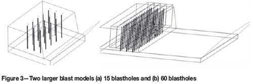
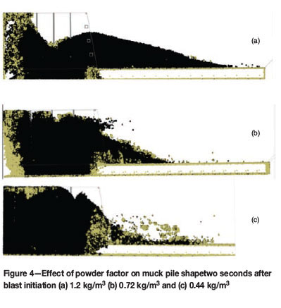
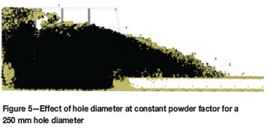
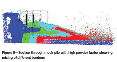
Two larger models were used to highlight the effect of changing firstly the burden and spacing and secondly the hole diameter. The models (shown in Figure 3) use 15 and 60 holes, respectively. The 15-hole model runs overnight on a six-core PC and the 60-hole model takes 4 days of run time. The decrease of powder factor by increasing the burden and spacing (keeping the ratio between them constant) significantly decreases the throw of the muck pile, as shown in Figure 4. The higher powder factor results in more throw and a flatter muck pile, as would be preferred for smaller excavating equipment. Larger shovels would prefer the more steeply heaped muck pile associated with the lower powder factors. The lower powder factor causes a less uniform fragmentation distribution and more large fragments that would be detrimental to smaller loading equipment. When the hole diameter changes, the distribution of the explosive within the rock mass is altered as a larger hole will require longer stemming, forcing the explosive mass further away from the surface. The burden also needs to increase, with the result that heave is diminished as is seen by comparing Figure 4a with Figure 5, where the hole diameter is increased from 165 mm to 250 mm. These subtleties are not always appreciated by mine production personnel and can adversely affect production. For example, the decision to improve drilling efficiency could severely compromise loading processes if the fragmentation and muck pile shape changes beyond the capability of the existing excavating equipment. By differently colouring the fragments derived from each row of holes, as shown in Figure 6, the model demonstrates the complexity of the mixing regime within the muck pile due to the interrelationship between the hole timing and the time it takes for fragments to fall to ground at a given ejection velocity. This complex interlayering is not intuitive and is not predicted by simpler blasting models. Misunderstanding of this is common and can lead to major inefficiencies in mines, where it is vital to distinguish between ore and waste to minimize dilution in the plant or limit valuable ore being sent to the waste dump (e.g. Wade, 2012)
Wall control case studies
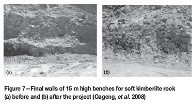
Having studied how the model can predict blast performance, it is useful to consider how it can contribute to the rock engineer's need to determine the damage associated with blasting. Two case studies are used to provide realistic scenarios for this analysis. Firstly, project interventions significantly improved the condition of the final walls in very weak kimberlite rock with a compressive strength that ranges from 8 MPa to 60 MPa, as shown in Figure 7 (Oageng, et al., 2008). These properties are lower than the those of the kimberlite used in the model as specified earlier. In this case the presplitting was originally done using set of 50 mm cartridges. Little improvement was seen when the 50 mm cartridges were spaced along the hole, and the best result was found when the trim blast timing was changed and the explosive distribution was limited to a line of cartridges of 25 mm diameter. Secondly, in similar conditions at the open pit, where the blasts described were performed, the mine used 38 mm and 32 mm cartridges distributed along the presplit holes in stronger kimberlite (Naidoo, 2006). In both cases many expensive tests were also required to evaluate different blasting options, which could be avoided if the model can be used to discard unsuitable options.
Wall control blasting techniques involve firstly creating a tensile presplit along the line of the final wall with closely spaced blastholes that contain low quantities of explosive, usually decoupled from the side of the blast holes. Then, production blasts are taken to remove rock until only three lines of holes remain in front of the presplit. The blasting of these last three lines is known as a trim blast and requires special care in the selection of blasting parameters to produce good wall control by limiting the explosive energy transmission and associated damage in the final wall.
The effect of presplit charge diameter on wall damage
The subsequent modelling loosely follows the blasting practices in these two studies to demonstrate how the choice of blast design parameters can affect the wall stability. For this paper we have selected the same model properties as described earlier and explosive properties equivalent to 50 mm or 38 mm cartridges of emulsion distributed along the holes at 1 m spacing. The model is shown in Figure 8 and has a portion excavated (shown in orange) to simulate the face of the previous trim blast. The model uses 19 presplit holes fired simultaneously, and then the trim blast holes with an explosive model simulating ANFO are fired 10 ms later from the front corner with a timing of 75 ms along rows and 42 ms between rows.

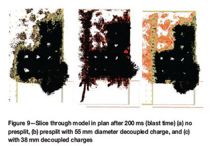
A section though the model after 200 ms is shown in Figure 9 for three different cases of no presplit, 50 mm cartridges, and 38 mm cartridges in a 165 mm blasthole. The case without presplit shows excessive back-break. When the presplit is taken with 50 mm cartridges, there is significant damage from the presplit itself though there is no further damage from the trim blast. This is similar to the situations described in the case studies. Once the cartridge diameter is reduced to 38 mm, then the split forms cleanly and there is limited damage (incomplete fractures) formed into the remaining highwall. The presplit shows more damage than expected, and this aspect is being addressed by the HSBM researchers.
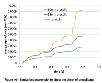
Many authors e.g. Onederra and Esen (2004) and Bye et al. (2005) relate peak particle velocity to damage. In order to demonstrate the effect of the presplit on the particle velocity, the cumulative energy equivalence is calculated from the velocity squared:

where VX and VY are the horizontal particle velocities perpendicular and parallel to the face, respectively, at the point shown in Figure 8. Figure 10 shows that there is a significant attenuation of the energy by the 50 mm presplit and less by the 38 mm split. Considering that the damage is less with the 38 mm presplit, design must maintain a balance between the damage caused by the split and the damage caused by the particle velocity. This needs to be compared to in situ measurements of particle velocity and damage.
The effect of blast timing in the trim blast on wall stability
The timing in the case study by Oageng et al. (2008) was altered to reduce the peak particle velocity acting towards the back by changing the timing contours to flatten the direction of heave and hence attempt to direct the particle velocity at flatter angle to the highwall. The two cases tested are shown in Figure 11, with Figure 11a showing the timing for the case with 33 ms between holes and 100 ms between rows, and Figure 11b showing the case with a longer time of 75 ms between the holes in the row and a shorter time of 42 ms between rows. In both cases, the presplit was modelled as a pre-exiting joint. The aim of this modelling study was to investigate whether the timing really influences the peak particle velocity significantly.
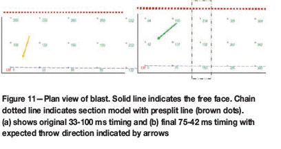
The arrows in Figure 11 indicate the conventional understanding of blast throw as being predominantly in the direction perpendicular to the timing contours. Slower timing along the free face leads to a more oblique heave direction effectively shearing the rock off the presplit face (Figure 11b) and hence supposedly inducing less reaction back into the remaining rock mass. The fracture patterns in section produced by the model in Figure 12 indicate similar trends in the direction of heave. However, the question of final wall stability relates to what happens behind the blast.
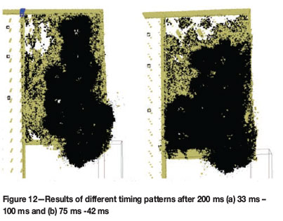
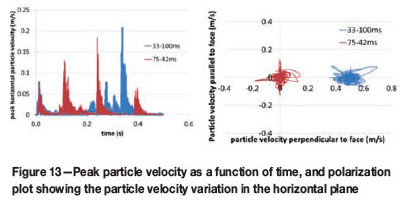
Figure 13a shows that the 33 ms -100 ms timing does produce the maximum horizontal peak particle velocity, though the 75-42 ms timing produces only slightly lower, but more frequent peaks. The polarization plot in Figure 13b shows that there is some change in the directions of the particle velocity vector between the two timing cases. There is, however, little difference in magnitude of the particle velocity components and the variation in angle suggested by the throw direction arrows is not evident.
Effect of the charge distribution in the trim
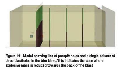
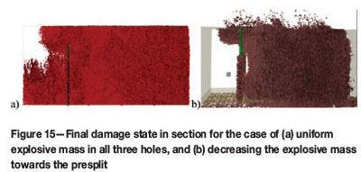
A simple model (shown in Figure 14) consisting of a single column of holes and a section of the presplit (shown on plan in Figure 3) is used to investigate the effect of changing the explosive distribution in trim blast on the damage behind the presplit. When all the trim holes all have the same amount of explosive, Figure 14a shows that damage (indicated as broken bonds in the DEM lattice) penetrates the presplit crack into the final wall. In contrast, when the explosive mass is reduced towards the back of the blast (Figure 14b) the presplit holes remain undamaged and protect the rock in the final wall position. Comparison with the limited effect of timing from the previous section suggests that, at least in a unjointed rock mass, the effect of reducing the charge is significantly more important in reducing damage than changing the timing.
Effect of joints
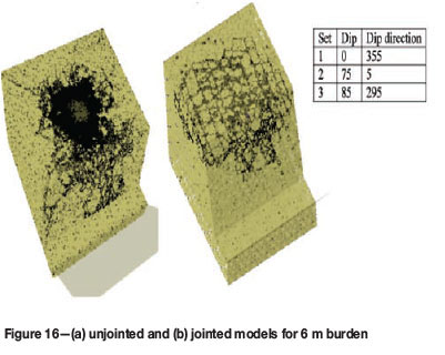
Up to now, the rock has been considered to be homogeneous. However, it is obviously jointed, and empirical evidence shows that the relationship between the hole spacing and the joint spacing has a significant effect on the fragmentation (Cunningham, 2005). The solid model was rerun using the case with 6 m of burden and three sets of characteristic joints using the average dip and strike measured in the field tests. The breakage pattern changed in the jointed rock mass, with fractures occurring preferentially around the blocks created by the joint pattern and not fragmenting the rock within, as shown in Figure 16. The overall fragmentation distribution becomes coarser in jointed rock (Sellers et al., 2012). Further work is required to investigate this effect and evaluate the sensitivity to the selected parameters and joint models.
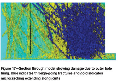
As a final example, the same set of joints in Figure 16 is applied to the trim blast model of Figure 14 to demonstrate how the joints transmit damage through the rock mass. Once the first hole has fired, as shown in Figure 17, the joints are fractured at least past the second row of holes. Damage in the form of partial opening extends all the way through the presplit. Thus, a single hole can cause damage at least two burden distances back into the final wall if the joints are orientated suitably.
Conclusions
The hybrid stress blasting model has been developed over the past ten years to model the dynamic response of the rock mass to blast loading. A number of different numerical codes have been coupled together to produce physically realistic outputs in the shortest possible time with a minimum of calibration factors and material parameters. The resulting code has been put through rigorous testing in validation studies at laboratory and field scales. A brief mention of some of the single-hole field tests in kimberlite indicates how the model is able to reproduce observed results and so is applied to investigate the effect of altering blast parameters. This enables a blaster to evaluate options without having to perform expensive tests on the mine.
The model predicts the increase in heave expected with higher powder factors and, less obviously, decreased throw for a larger diameter at the same powder factor. These subtle changes in outcome with altered blast parameters are not often understood on the mines, with negative effect on downstream production. The ability to visualize these outcomes, and others such as the mixing of the rock within the muck pile, is vital to enable miners to improve and optimize production.
Moving to studies of wall control, the model is able to inform rock engineers regarding the extent and degree of damage caused by blasting. By modelling presplits in kimberlites at large open-pit mines, the model confirms that larger cartridge diameters in the decoupled charge cause increased damage into the final pit wall. Decoupled explosives do, however, need more attention in the model development. Monitoring of seismic wave transmission shows that changing timing does not significantly alter the total energy transmitted, but alters when the peaks occur. Thus, in this homogenous rock mass, the model indicates that reducing the charge towards the back of the trim blast plays a much more significant role in decreasing back damage than altering the timing, which is contrary to many expectations and invites further study. The final choice of blast parameters will need to balance the two opposing effects. The model predicts a very different fragmentation pattern in jointed rock and shows that separation along weaker planes can extend the damage a distance of at least twice the burden behind from the blasthole. These studies have shown how little is known of the dynamics of the rock mass response to blasting, and the model development process has provided a huge step in understanding. The current model validation project, which will be completed by the end of 2012, aims to compare these insightful models with more field tests to improve the confidence of the modellers that any results presented to blasters or rock engineers will correctly reflect the explosive-rock interactions to be expected in any given situation.
References
1. Braithwaite, M. and Sharpe, G. 2009. Simulation of real detonations as an energy source term for the Hybrid Stress Blasting Model. Fragblast 9. Proceedings of the 9 th International Symposium on Rock Fragmentation, Grenada, Spain, 13-17 September. Sanchidrian, J.A. (ed. [ Links ]).
2. Bye, A.R., Little, M.J., and Mossop, D.H. 2005. Slope stability risk management at Anglo Platinum's Sandsloot open pit. 1st International. Seminar on Strategic versus Tactical Approaches in Mining, Sandton, South Africa, September 2005. pp. 205-224. [ Links ]
3. Cundall, P.A. and Detournay, C. 2008 Modeling shock and detonation waves with FLAC. Proceedings of the 1st International FLAC/DEM Symposium on Numerical Modeling, 25-27 August, Minneapolis, USA. [ Links ]
4. Cunningham, C.V.B. 2005. The Kuz-Ram fragmentation model - 20 years on. Third EFEE World Conference on Explosives and Blasting, Brighton, UK, Holmberg, R. et al. (eds). European Federation of Explosives Engineers, 2005. pp. 201-210. [ Links ]
5. Furtney, J.K., Cundall, P.A., and Chitombo, G.D. 2009, Developments in numerical modeling of blast induced rock fragmentation: Updates from the HSBM project. Fragblast 9. Proceedings of the 9th International Symposium on Rock Fragmentation by Blasting. Granada, Spain, September 2009. pp. 335-342 [ Links ]
6. Furtney, J., Sellers E., and Onederra, I. 2012. Simple models for high pressure gas flow during blasting. International Society of Explosives Engineers. Nashville, Tennessee. [ Links ]
7. Furtney, J.K., Cundall, P.A., Onederra, I., and Sellers, E. 2011. Numerical modeling of rock blasting: validation tests for blo-up. continuum and distinct element numerical modelling. Geomechanics, 2011. 2nd International. FLAC/DEM Symposium, Melbourne, Australia. Sainsbury, D. etal. (eds). Itasca. pp. 359-368. [ Links ]
8. Itasca Consulting Group, Inc. 2008. LAC (Fast Lagrangian Analysis of Continua), Version 6.0. Minneapolis, USA. [ Links ]
9. Naidoo, V. 2006. Presplit project. Workshop for Explosive Engineers, AEL Mining. [ Links ]
10. Oageng, K., Joseph, R.O., and Munyadzwe, I. 2008. Perimeter control at Orapa Diamond Mine. Surface Mining Conference. The Southern African Institute of Mining and Metallurgy. pp. 137-152. [ Links ]
11. Onederra, I. and Esen, S. 2004. An alternative approach to determine the Holmberg-Persson constants for modelling near field peak particle velocity attenuation. Fragblast, vol. 8, no. 2. pp. 61-84. [ Links ]
12. Onederra, I. and Grobler, H. 2004 Single and multiple hole blasting tests. Report submitted to the HSBM Project. [ Links ]
13. Onederra, I., Cundall, P., Furtney J., and Chitombo, G. 2009, Towards a complete validation of the lattice scheme in the Hybrid Stress Blasting Model (HSBM). Fragblast 9. Proceedings of the 9th International Symposium on Rock Fragmentation by Blasting, Granada, Spain, September 2009. pp. 343-351 [ Links ]
14. Potyondy, D.O. and Cundall, P.A. 2004. A bonded-particle model for rock. International Journal of Rock Mechanics and Mining Sciences, vol. 41. pp. 1329-1364. [ Links ]
15. Rogers, W., Kanchibotla, S.S., Tordoir, A., Ako, S., Engmann, E., and Bisiaux, B. 2012. Understanding blast movement and its impacts on grade control at Ahafo Gold Mine in Ghana. International Society of Explosives Engineers. Nashville, Tennessee. [ Links ]
16. Sellers, E., Furtney, J., and Onederra, I. 2012. Field-scale modelling of blasting in kimberlite using the Hybrid Stress Blasting Model. International Society of Explosive Engineers. Nashville, Tennessee. [ Links ]
17. Sellers, E., Kotze, M., Dipenaar, L., and Ruest, M. 2009. Large scale concrete cube blasts for the HSBM model,Sanchidrian, J.A. (ed). Fragblast 9. Proceedings of the 9th International. Symposium on Rock Fragmentation, Granada, Spain, 13-17 September. [ Links ]
18. Sellers, E.J. 2011 Controlled blasting for safety - examples and illustrations. Journal of the Southern African Institute of Mining and Metallurgy, vol. 111, no. 1. pp. 11-17. [ Links ]
© The Southern African Institute of Mining and Metallurgy, 2012.ISSN2225-6253. This paper was first presented at the, Southern Hemisphere International Rock Mechanics Symposium (SHIRMS) 2012, 15-17 May 2012, Sun City, South Africa.

