


Services on Demand
Article
 English (pdf)
 Article in xml format
 Article references
Indicators

Related links
-
 Cited by Google
 -
 Similars in Google
Share

 Permalink
Journal of the Southern African Institute of Mining and Metallurgy
On-line version ISSN 2411-9717
Print version ISSN 2225-6253
J. S. Afr. Inst. Min. Metall. vol.112 n.7 Johannesburg Jul. 2012
TRANSACTION PAPER
The dual-electrode DC arc furnace-modelling brush arc conditions
Q.G. Reynolds
Mintek, Johannesburg, South Africa
SYNOPSIS
The dual-electrode DC arc furnace, an alternative design using an anode and cathode electrode instead of a hearth anode, was studied at small scale using computational modelling methods. Particular attention was paid to the effect of two key design variables, the arc length and the electrode separation, on the furnace behaviour. It was found that reducing the arc length to brush arc conditions was a valid means of overcoming several of the limitations of the dual-electrode design, namely high voltages and arc deflection.
Keywords: pyrometallurgy, furnace, DC, reverse polarity, dual-electrode, brush arc.
Introduction
Direct-current (DC) plasma arc furnaces are seeing increased industrial use in the field of ore smelting, particularly for ferrochrome and ferronickel applications1,2. Scaling up to high power levels for new greenfield plants has necessitated multiple-cathode designs which are capable of carrying twice or more the current of traditional single-electrode furnaces, while at the other end of the spectrum interest has developed for retrofitting existing furnace vessels of various types for DC operation - one method of accomplishing this is the dual-electrode concept3,4 as shown in Figure 1.
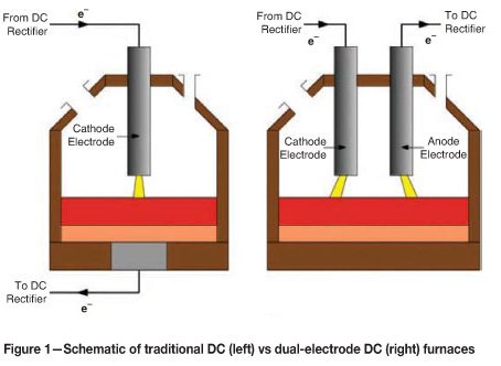
The dual-electrode furnace uses two graphite electrodes, one connected as cathode, the other as anode. Electric current is passed from the DC rectifier to the anode, through a plasma arc to the molten bath, through the bath, and through a second arc at the cathode, which is connected back to the rectifier to complete the circuit.
This type of furnace has several advantages4, key among them being the ability to avoid using a conductive hearth anode. Hearth anodes are specialized designs unique to DC furnaces, and would require a complete rebuild of the furnace shell and lining together with any licensing and specialised manufacturing required for the anode design used. This would add considerably to the capital cost in the case of a retrofit.
The avoidance of the hearth anode design does, however, come with some penalties4. The presence of two arcs (and two arc attachment zones on the slag bath) connected in series means that the furnace will typically operate at higher voltages compared to a single-electrode design at comparable power and arc lengths. Additionally, magnetic interaction between the two arcs results in a repulsive force acting on the arc jets, causing deflection of the arc columns away from the centre line of the furnace and toward the sidewalls. This can cause secondary flow patterns in the both the gas and liquid phases in the vessel, which result in additional thermal loading on the furnace lining in the regions adjacent to the two electrodes.
Similar problems occur in three-electrode circular AC furnaces. The negative effects can be mitigated in such furnaces by moving to a brush arc mode of operation, in which the distance between the tip of the electrodes and the molten bath surface is substantially reduced. The brush arc mode retains many of the advantages of DC open-arc open-bath operation, and has been successfully implemented on industrial ferroalloy AC furnaces5,6. It is therefore of some interest to examine the effect of reducing the arc length on the behaviour of the dual-electrode DC furnace.
It should be noted that operating under brush arc conditions can potentially introduce additional difficulties. Due to the proximity of the electrodes to the molten slag, splashing and vertical movement of the bath surface may change the arc length or even extinguish the arc temporarily, resulting in large fluctuations in the electrical parameters of the furnace; these would need to be appropriately accounted for and limited in the control methodology used. Splashing of molten process material onto the electrodes may also be exaggerated at short arc lengths and cause increased electrode wear by chemical and thermal erosion - this problem is, however, well understood from AC furnace experience.
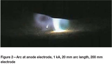
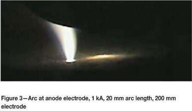
An additional problem with moving to brush arc operation is the potential for the arc jet direction to become reversed (that is, the arc gases begin to flow from the surface of the bath up toward the electrode, rather than from the electrode surface down toward the bath). This can occur since the electrode surface and bath surface look increasingly like two flat, parallel, symmetric plates relative to the dimensions of the arc as the arc length is reduced, and the directionality of the arc jet flow is determined primarily by the geometric asymmetry of the conducting surfaces4. Some examples from high speed imaging of DC plasma arcs in a flow-reversal condition at short arc lengths are shown in Figures 2 and 3. For this work, an Olympus iSpeed 3 high-speed digital video camera was used to film the arc. The camera used a 200 mm f/22 lens, and was set to record at 5000 frames per second and 4 µs shutter speed.
Test work has indicated that increasing the furnace current increases the arc jet's tendency to travel in the usual direction, from electrode surface down to bath. In general the arc is considerably more unsteady at higher currents, but the jet direction as shown in Figures 4 and 5 is clearly from electrode to bath.
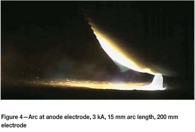
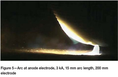
This change is most likely due to the fact that the forces that act on the arc scale in proportion to the square of the current, and small asymmetries in the geometry are greatly exaggerated at higher current levels. Such jet reversal issues are therefore not expected to occur in industrial-scale furnaces operating at a few kiloamperes or more.
Plasma arc model
Direct current plasma arcs are strongly coupled problems. Separate models of fluid flow, energy transfer, and electro-magnetism are needed, and must be solved simultaneously using numerical methods in order to obtain an overall model of arc behaviour. The governing equations as used in the present work are given below.
Fluid flow:
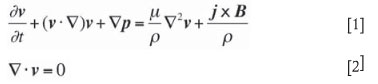
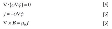
Heat transfer:
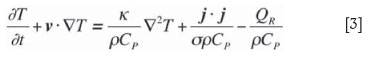
Electromagnetic fields:
where
v is the plasma velocity vector
t is time
p is the reduced pressure (=P/p)
µ is the plasma viscosity
p is the plasma density
j is the current density vector
B is the magnetic field vector
T is the plasma temperature
k is the plasma thermal conductivity
Cp is the plasma heat capacity
σ is the plasma electrical conductivity
QR is the volumetric radiation energy loss
Ф is the scalar electric field
µ0 is the free-space magnetic permeability.
Both σ and QR are strong functions of the plasma temperature T.
These equations must be solved using an appropriate numerical scheme that takes into account the strong time dependence of the arc evolution problem as well as the coupling effects. The various fields must also be supplied with appropriate initial and boundary conditions for the particular problem being studied. The models are solved in three dimensions in order to fully capture the spatial behaviour and interactions of the arcs. Further details can be found in earlier publications7,8.
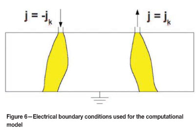
For the dual-electrode case, the electrical boundary conditions and solution region are shown in Figure 6. Current density (the local gradient of the electric potential field) is specified on each of two arc attachment zones for the anode and cathode arcs as equal and opposite in magnitude, to simulate the passage of current down one electrode and up the other in the dual arrangement. Current density at the arc attachment zones is taken as jk = 3.5 kA/cm2 from Bowman's work9. The roof and walls are assumed to be electrically insulating, and the bath surface is assumed to be at ground potential.
The numerical algorithm was implemented in ANSI C code and compiled for execution on computers running 32-bit Ubuntu Linux 10.04 using GCC 4.3.1. The FFTW library10 was used to accelerate parts of the solver routine, and the OpenMP library provided multi-threaded parallelization.
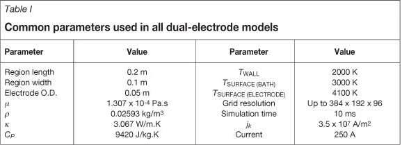
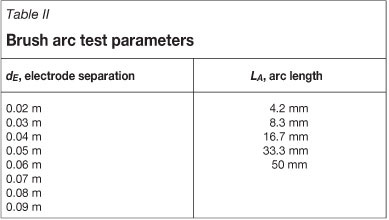
The common simulation parameters used for all dual-electrode test cases are shown in Table I. The physical property data assumes air as the plasma gas. Table II shows the range of arc length (equal to the simulation region height) and electrode separations (the distance between electrode centre lines) tested for the brush arc study. Every combination of these two parameters was tested, resulting in 40 simulations in total.
Each simulation was run for 10 ms of model time from initial conditions (arc ignition). Some parts of the data analysis required time-averaged values of the fields in the model - in these cases, a time average of the last 2 ms was taken.
Results and discussion
Variation of temperature distribution
Figures 7 to 11 show qualitatively the effect of changing the arc length from longest to shortest at a fixed electrode separation of 0.04 m. Projected time-averaged temperature fields show the maximum value of T in the y-axis direction, reducing the field dimensionality from 3D to 2D. The scale shown ranges from 2000K (white) to 15000K (black).
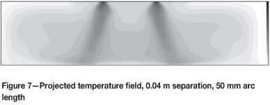
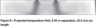
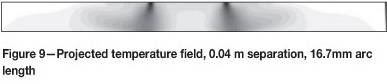
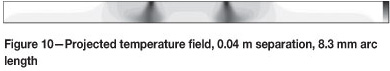
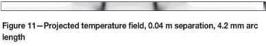
Several changes are visible as the arc length is reduced to brush arc conditions. Firstly, the arcs become more localized in space, with greatly reduced thermal interaction in both the space between them and the region surrounding them. This is due to more compact recirculation patterns developing around the arc jets as they become confined by the electrode and bath surfaces at short arc lengths, which act to hold the hot plasma gases closer to the arc column. Secondly, due to the shortened distance the jets have to travel before they reach the bath surface, the arcs do not appear to deflect each other as much at shorter arc lengths.
Magnetic field consistency check
One of the primary aims of the brush arc test cases is to examine the effects of interaction and deflection of the arcs, and it is therefore important to verify that the magnetic field calculations in the model are being performed in a consistent and repeatable way. The self-magnetic field around the arc columns (together with the current density field from which it is derived) is the source of the deflection forces that act to push the arc jets apart. Some examples of the three-dimensional magnetic field at different arc lengths are shown in Figures 12 to 14.
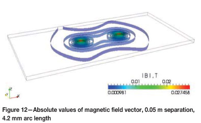
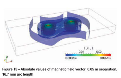
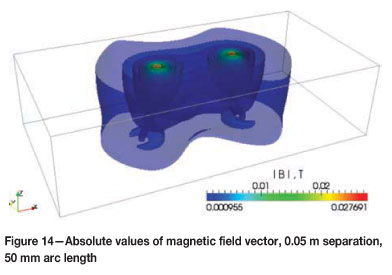
The calculated peak magnitudes of the magnetic fields, which are generally found only within the core of the arc attachment zones on the electrode surfaces, lie within 3.5 per cent of each other across a wide range of arc lengths. This suggests that the magnetic and electric fields are being predicted consistently at different arc lengths, and the change in region dimensions is not adversely affecting the calculation.
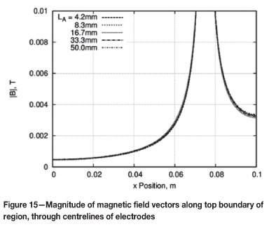
An additional cross check is shown in Figure 15, for an electrode separation of 0.05 m (defined as the centre-to-centre distance between electrodes). Here, the magnetic field profile in the x-direction at the top surface of the calculation region, along the centre line of the two arcs, is given for all arc lengths tested. The curves lie very close together, confirming that the magnetic field calculation, and therefore arc deflection calculation, is consistent across different arc lengths.
Voltage behaviour
As the arc length is reduced to brush arc conditions, the system voltage (calculated as the difference between the maximum and minimum of the electric potential field) for the dual-electrode configuration reduces considerably. Evolution of the voltage over the duration of the simulation for selected example cases is shown in Figure 16.
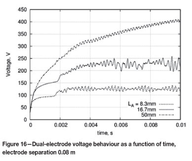
Much higher voltages are obtained with longer arcs. It is interesting to note that the voltage in the case of arc length LA = 50 mm does not appear to have reached steady state by the end of the simulation, suggesting that an increased run time would show even greater disparities.
Calculating time-averaged voltages and comparing all the dual-electrode model cases gives the results shown in Figure 17.
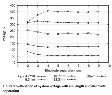
The gross behaviour of voltage increasing with increasing arc length is confirmed by these results; however, the shape of the curves has some interesting subtleties. In general, at large dE the voltage remains constant with separation for a given arc length. As dE decreases, the voltage first rises slightly, and then drops (this is particularly noticeable at longer arc lengths). The reason for this is that as the arcs are brought closer together they repel each other more, causing more deflection. The increased deflection results in a longer current path and hence an increase in system voltage. This effect is, however, rapidly mitigated when the arcs are placed in extreme proximity to one another, as the gas in the region between them becomes heated to the point at which it starts to conduct electricity. This results in some of the current flow short-circuiting directly between the arcs4 instead of travelling through the bath, reducing the length of the current path significantly and causing the voltage to drop.
Arc deflection
The absolute deflection is defined as the separation between the two arc columns at the level of the molten bath. Arc deflection occurs in the dual-electrode models as a result of electromagnetic interaction between the two arc columns carrying current in opposite directions. It is measured by calculating a time-averaged three-dimensional temperature field for each case, and then finding the distance between the two temperature maxima at the bath surface (lower boundary in the model). This value is compared across all dual-electrode model cases in Figure 18.
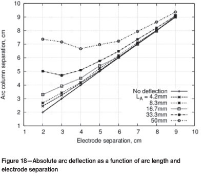
It can be seen that decreasing the arc length to brush arc conditions greatly reduces the absolute deflection, particularly at smaller electrode separation values. The minimum in absolute deflection also moves closer to the centre of the furnace as the arc length is reduced.
Arc deflection can also be calculated using a relative definition, which normalizes the data relative to the dimensions of the arc and system being studied. One intuitive way to do this is to calculate the angle at which the arc jets are deflected. This is done using the formula below:
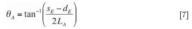
Here, ФA is the arc deflection angle, and sE is the absolute deflection as defined above. The arc deflection angle is measured between the arc column and the vertical. The variation of the deflection angle with model parameters for all dual-electrode model cases is shown in Figure 19.
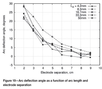
Reducing the arc length has somewhat less of an effect on the arc deflection angle than it does on the absolute deflection; however, there is still a noticeable trend to lower angles (more vertical arc columns) at shorter arc lengths. A possible explanation for this phenomenon is that the arc jet initially travels nearly perpendicularly to the surface of the electrode due to the very high velocities imparted by the Lorentz forces (which arise due to the interaction between the arc current j and the self-magnetic field B) in the immediate vicinity of the arc attachment spot, and only further down the column do the magnetic repulsion effects from the opposite arc column start to dominate and push the jets apart. Some qualitative evidence of this can also be seen in the temperature profiles shown in Figures 7 to 11.
Lateral blast
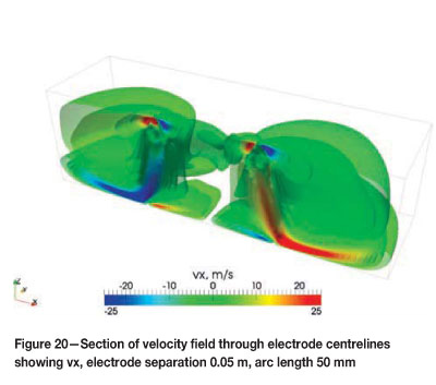
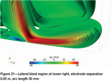
Lateral blast is defined as the peak velocity of the arc gases in the horizontal direction. For the purposes of the present study, the lateral blast is measured in a vertical plane positioned at the outer edge of the electrodes. This value gives a measure of how much momentum is imparted to the gases in the furnace freeboard by the deflection of the arc columns, and gives an indication of the degree to which the hot gases and molten slag in the bath will be driven toward the furnace sidewalls.
Figures 20 and 21 show 3D plots of the x-component of the time-averaged velocity field for an example model case. Areas of strong horizontal velocity are visible in red and blue, near to the bath surface at the bottom of the region.
Lateral blast values for all dual-electrode model cases were calculated using time-averaged velocity fields and are compared in Figure 22.
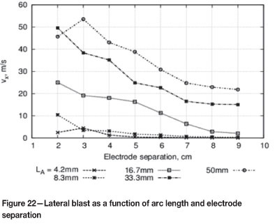
Lateral blast velocities are seen to decrease both as the electrode separation increases, and as the arc length decreases. The effect of reducing arc length is pronounced, with the lateral blast falling away to negligible levels for the shortest arc lengths tested. This result is predominantly due to two effects. Firstly, as the electrode separation increases, the deflection of the arc columns decreases, causing less of the arc jet to be diverted toward the furnace sidewalls. Secondly, decreasing the arc length results in smaller, more compact recirculation zones around the arc jet as it is confined between the electrode and bath surfacesas a result, most of the arc gases are drawn back into the arc before they can impart much momentum to the surrounding fluids.
CONCLUSIONS
The dual-electrode furnace has been modelled at small scale using computational methods. This model has been successfully applied to a study of the effect of certain important design variables, namely electrode separation and arc length, on the behaviour of and interactions between the arc columns at the anode and cathode electrodes.
Accuracy of the magnetic field calculation across a range of arc lengths was verified. Results of the system voltage calculations showed a very strong dependence of voltage on arc length, with shorter brush arc lengths consistently producing the lowest voltages. Deflection of the arc columns away from each other in accordance with theoretical understanding was confirmed qualitatively using visualizations of the temperature fields. Deflection was also measured quantitatively, and found to be reduced at short arc lengths. A side effect of deflection, lateral blast velocity, confirmed this result with much lower velocities being predicted in the models at short arc lengths.
In summary, the modelling work conducted suggests that operating dual-electrode type furnaces in brush arc conditions is potentially a means of overcoming several limitations of the design. Some additional difficulties may be introduced, but it is expected that careful design of the control system and electrodes would be able to address these issues.
Future work should include experimental testing of the dual-electrode concept at pilot scale. Visual and electrical measurements during such a test campaign would complement the largely theoretical results presented here.
Acknowledgements
This paper is published by permission of Mintek. The author would also like to thank GLPS for productive discussions and permission to use the photographs in Figures 2 to 5.
References
1. SAGER, D., GRANT, D., STADLER, R., and SCHREITER, T. Low cost ferroalloy extraction in DC-arc furnace at Middleburg Ferrochrome. Journal of the Southern African Institute of Mining and Metallurgy, vol. 110, no. 12, December 2010. pp. 717-724. [ Links ]
2. NAUDE, C.P. and SHAPIRO, M.D. Implementation of the first commercial scale DC smelter for ferronickel production from low grade laterite ores technology building blocks and lessens learned. Journal of the Southern African Institute of Mining and Metallurgy, vol. 110, no. 12, December 2010. pp. 725-732. [ Links ]
3. GREYLING, F.P. and GREYLING, H.W. DC Brush Arc Furnace for Ferrochrome Production. South African Patent Application 2010/06472, 2010. [ Links ]
4. REYNOLDS, Q.G. The dual-electrode DC arc furnacemodelling insights. Journal of the Southern African Institute of Mining and Metallurgy, vol. 111, no. 10, October 2011. pp. 697-703. [ Links ]
5. WALKER, C., SUTHERLAND, K., MARSHALL, B., GELDENHUIS, J.M.A., ELS, J., VOERMANN, N., and WASMUND, B. Conversion to partially open bath smelting on Highveld ironmaking furnaces. Proceedings of the European Metallurgical Conference2007, June 11-14, Dusseldorf (Germany), 2007. pp. 895-914. [ Links ]
6. STEINBERG, W.S. Development of a control strategy for the open slag bath furnaces at Highveld Steel and Vanadium Corporation Ltd. MIng dissertation, University of Pretoria (South Africa), 2008. [ Links ]
7. REYNOLDS, Q.G., JONES, R.T., and REDDY, B.D. Mathematical and computational modelling of the dynamic behaviour of direct current plasma arcs. Journal of the Southern African Institute of Mining and Metallurgy, vol. 110, no. 12, December 2010. pp. 733-742. [ Links ]
8. REYNOLDS, Q.G. and REDDY, B.D. Some aspects of dynamic computational modelling of direct current plasma arc phenomena. Proceedings of Coupled Problems 2011, June 20-22, Kos Island (Greece), 2011. Paper no. p. 135. [ Links ]
9. BOWMAN, B. Properties of arcs in DC furnaces. Proceedings of the 52nd Electric Furnace Conference, November 13-16, Nashville (USA), 1994. pp. 111-120. [ Links ]
10. http://www.fftw.org. [ Links ]
Paper received Jan. 2012
Revised paper received Mar. 2012

