


Serviços Personalizados
Artigo
 Inglês (pdf)
 Artigo em XML
 Referências do artigo
Indicadores

Links relacionados
-
 Citado por Google
 -
 Similares em Google
Compartilhar

 Permalink
Journal of the Southern African Institute of Mining and Metallurgy
versão On-line ISSN 2411-9717
versão impressa ISSN 2225-6253
J. S. Afr. Inst. Min. Metall. vol.112 no.3 Johannesburg Mar. 2012
JOURNAL PAPERS
Khumani Iron Ore Mine paste disposal and water recovery system
T. du ToitI; M. CrozierII
IKhumani Iron Ore Mine, Assmang, South Africa
IIWesTech Process Equipment Africa Pty Ltd, South Africa
SYNOPSIS
Traditional iron ore beneficiation plants using washing, screening, and jigging processes require large volumes of process water. However, when a suitable large iron ore deposit is found in a location where rainfall is erratic and raw water sources are limited, innovative process designs are required to minimize water losses, maximize re-use of process water, and minimize raw water intake to ensure the project viability.
This case study provides an overview of the Khumani paste disposal facility (PDF) located in the Northern Cape Province of South Africa. The plant uses a central ring main water reticulation circuit combined with a two-stage thickening system to maximize water recovery.
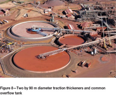
At the process plant there are two large 90 m diameter traction thickeners and at the PDF two 18 m paste thickeners. The net raw water usage has been minimized, and water losses on the PDF are at levels of between 0.43 to 0.69 m3/t deposited.S
Keywords: Khumani, paste thickening, paste disposal facility, iron ore, water recovery.
Introduction
Khumani Iron Ore Mine is situated in the Northern Cape Province of South Africa adjacent to Kumba's Sishen Mine and approximately 30 km from Kathu.
Formally known as the BKM Project after the farms the iron ore deposits are located on (Bruce, King) and Mokaning, the mine is part of Assmang Limited which is jointly owned by African Rainbow Minerals and Assore Limited.
The first phase of Khumani was commissioned in 2008 with initial production of 8.4 Mt/a per annum of iron ore exported through Saldanha Bay on the west coast of South Africa. The second phase increasing production to 16 Mt/a is due for final completion in 2012; life of mine is in excess of 25 years.
The Northern Cape has a semi-arid climate with historical rainfall of approximately 330 mm mainly between October and April. The evaporation rates are high, with reported values of around 1 900 mm/a. The area supports a number of large mining ventures, and allocations of raw water by the Department of Water Affairs are limited and carefully managed.
This led to a number of challenges as the preferred process flowsheet involved wet processing due to the high clay content associated with the orebodies at Khumani.
The paper presents an overview of the Khumani operations focusing on the water management and paste disposal facility, which during the initial production of 8.4 Mt/a (phase 1a) minimizes raw water consumption to levels below 0.09 m3/t of product.
Integrated water management design considerations at Khumani mine
In the design phase it became clear the design team was going to have to optimize water recovery and re-use of available water at Khumani mine. The allocation level of raw water from the Gamagara water line by the Department of Water Affairs meant an overall consumption of raw water less than 0.09 m3/t of product was desirable.
The processing option selected after primary and secondary crushing involved wet washing and screening, jigging, and fines recovery through the operation of de-grit cyclones. Each of these processes requires large volumes of water and dilute slurries.
The use of conventional large-diameter (90 m) traction thickening technology was a proven process at the nearby Assmang Beeshoek iron ore operations some 60 km away. However, concerns over high evaporations rates in the area, lack of suitable sites for a conventional tailings facility, and the inability of this type of traction thickening technology to produce consistently high underflows densities for the desired water balances meant the design team needed to explore alternative thickening and disposal options to maximize water recovery.
Paste thickening technology had been successfully implemented some 250 km away by De Beers on their CTP diamond operations in Kimberly, as described by Houman and Johnson (2003)1, so the obvious question was could we use the same technology for iron ore processing operations.
Figures 1 illustrates graphically the theoretical water consumption based on 12% slimes and 14% slimes in cubic metres per ton of iron ore product for various thickening options ranging from conventional thickening through to paste thickening.
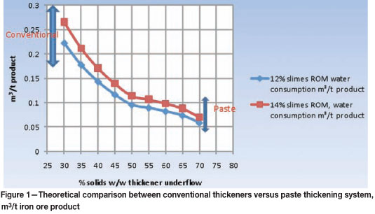
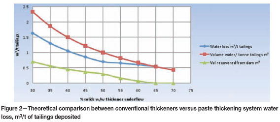
Figure 2 illustrates the theoretical volume of water lost and water recovered at the tailings facility for varying thickener underflow densities ranging from conventional thickening through to paste thickening. The data assumes 30% recovery of water from the tailings dam up to 50% solids by mass in the thickener underflow, decreasing to zero at 65% solids by mass in the thickener underflow.
Characterization bench-scale thickener test work commenced in July 2004. This was followed up by pilot plant test work in November and December 2004. The data produced in this work was used for the Class 0 (± 30%) prefeasibility study and for the Class 2 (±10%) feasibility study for the Khumani project that was completed in May 2005. Commissioning of phase 1 started in January 2007 and was completed by April of the same year. The detail design for phase 2, the Khumani Expansion Project (KEP) was, completed in March 2010. Commissioning of the additional primary traction thickener and the additional secondary paste thickener started in April 2011.
The design of the thickening system was an integrated approach marrying upstream process requirements of the processing plant with the thickening, pumping, and deposition limitations. Results from the bench-scale and pilot plant work conducted on Beeshoek material were used by all parties in this iterative system design. Furthermore, process data and client experience from the existing thickener installation at Beeshoek were used to refine the design and control philosophy. All test work was based on Beeshoek material, and the assumption was made that the material treated at Khumani would have similar characteristics.
A suitable paste residue site was identified on the King property some 5 km away, where the natural sloping contours would encourage run-off for the early stages of the project and the area had adequate storage capacity for the life of mine. Overburden from the King North Pit located nearby could be used for the construction of the embankment in the early stages of the dam construction, thus optimizing construction costs. Furthermore, in the early stages water from the paste facility could gravitate back to the Parsons operations due to the elevation change between the locations.
The final design incorporates the combination of proven large primary traction thickening technology at the main processing plant at Parsons together with secondary water recovery using paste thickening technology located at the King property. A ring main system exists at Parson Plant, where the return water recovered from the paste thickeners at the King paste disposal facility is fed back continuously.
Test work and feasibility studies
The test work was to establish if paste thickening was a plausible option, and then to subsequently size the thickeners, pumping system, and paste disposal facility. This was carried out in two separate phases on Beeshoek material as no samples of Khumani ore existed at that stage:
Bench-scale laboratory test work
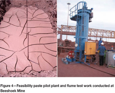
The bench-scale test work2 included mineralogy, water analysis, particle size analysis, flocculant type, flocculant optimization, flocculant demand tests, feed solids optimization tests, and settling characterization tests (Figure 3) by means of raked cylinders and rheological analysis using a Haake VT550 vein viscometer and '50 cent' Rheometer at various solids concentrations.

The details results of this test work were as follows:
confidence level in the data over an extended period on samples diverted from Beeshoek 90 m traction thickener underflow which at the time was not using any flocculant (Figure 4).
The results of the pilot plant test work3 indicated:
- the wide range of particle size distributions of the feed stream
- the variation of the feed solids concentration
- a variation of in situ mineralogy.
Paterson & Cooke Consulting Engineers conducted pump loop tests on material collected at the time of the pilot plant test work for the sizing of the pipelines and underflow pumping system.
Khumani paste disposal design objectives4
In order for the project to succeed, optimization of water recovery for re-use of clean water on the process plant was the overriding objective in the light of the scarcity of water, erratic rainfall conditions, and the need to prevent the contamination of the valuable groundwater resource in the region. A water consumption of 0.09 m3/t of product was required, in which at least 70% of the water in the underflow from the primary thickener would be recovered by the paste thickener. Allied to this the PDF objectives were to:
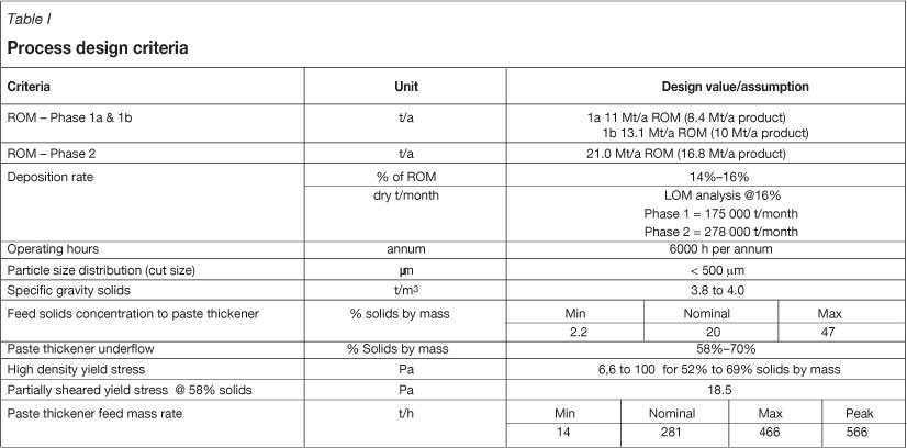
Khumani process design criteria
Process design criteria for the paste disposal facility are shown in Table I.
Khumani design5
The iron ore at Khumani is mined in a series of open pits by conventional drill-blast techniques and loaded into trucks for transport to primary and secondary crushers at the respective mine sites.
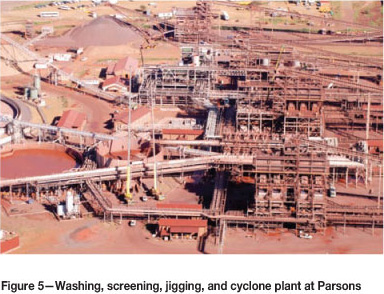
The run of mine is stockpiled on blending beds in two categories, on-grade and off-grade. The on-grade is washed and screened to produce a final product, and similarly the off-grade is also washed and screened, with the oversize material going through tertiary crushing, followed by further benefi-ciation through jigs to remove contaminants (Figures 5 and 6).

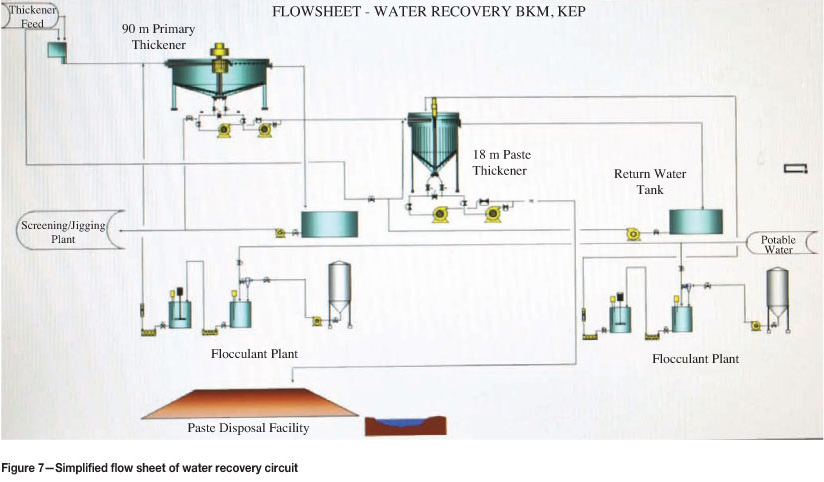
The water recovery, clarification, and paste production process
The plant consists of two thickeners, a 90 m diameter primary thickener situated at the main plant and an 18 m diameter paste thickener at the PDF for phase 1. An additional 90 m diameter primary thickener as well as an additional paste thickener was installed in phase 2 in the same configuration. The primary thickener recovers most of the water (approximately 95% by volume). The underflow from the primary thickener is pumped a distance of approxi-
mately 5 km to feed the paste thickener at the PDF. The paste thickener is required to recover at least 70% of the water in the underflow of the primary thickener, which is then pumped back to the main plant. The water returned from the primary thickener as thickener overflow has a solids concentration less than 50 ppm (Figures 7 and 8).
Thickener sizing, selection, and design
The primary thickeners
The primary thickeners operate as clarifiers returning the bulk of the clarified water to the main plant (12 000 to 15 000 m3/hr with a maximum of 18 000 m3/h). These thickeners were sized on the basis of the hydraulic loading.
Each primary thickener is equipped with a turbidity meter and an Alcotech flocculant-saving device. Flocculant is added in proportion to the response of the output signals from these instruments.
The feedwell diameter (14.6 m) has been designed on a feedwell duty of 1.5 m/min and a residence time of 1.5 min at a flow rate of 15 000 m3/h. The feedwell has a sloping (45°) bottom shelf. The objective is to divert the coarse particles toward the centre cone of the thickener to prevent mounds of coarse particles becoming isolated in one area of the thickener. This reduces slumping and torque spikes. A flat shelf has been avoided in order to prevent solids buildup on the shelf.
The feedwells of each of the WesTech 90 m diameter thickeners have been appropriately designed using computerized fluid dynamics (CFD) modelling to:
The feed to each primary thickener is from an elevation of greater than 5 m. The energy of the feed, with a volumetric flow rate in excess of 12 000 m3/h is high and requires damping and dissipating before entry into the feedwell of the thickener. This was achieved by the installation of a boiler box prior to entry to the feedwell. The feed is 'held up' in the feed pipe preceding the boiler box by means of a knife gate controlled through a level control device situated upstream in the feed launder. This flooded system reduces the velocity of the feed stream in order to reduce turbulence in the feedwell of the thickener and to protect the structure of the launder and the feedwell itself.
The secondary paste thickeners
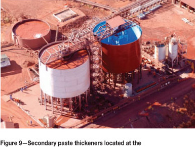
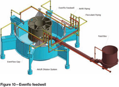
The size of the two secondary paste thickeners was determined from the residence time required for the slurry in the compaction zone to reach terminal solids concentration at optimum bed height. Hydraulic loading was also an important consideration, since internal as well as external dilution is necessary at high feed rates. The paste thickeners or secondary thickeners at the King site are 18 m diameter paste thickeners, having approximately a 12 m sidewall height and a cone angle of 30°. The thickeners have two rakes each with scraper blades and 16 vertical pickets. Feed is introduced to individual feed boxes, which feed the respective thickeners. The phase 2 paste thickener has the new Evenflo™ feedwell installed, custom designed to optimize flocculant consumption and throughput using single phase CFD modelling (Figures 9 and 10).
Each of the two secondary paste thickener systems accommodates feed tonnages varying from a nominal 147 t/h to 300 t/h. Tonnages up to 450 t/h can be buffered in each of the secondary paste thickeners for short intermittent periods. However, for feed tonnages greater than 300 t/h, and sustained over longer periods, a short emergency underflow pipeline is employed which allows higher volumes of slurry to be removed from the underflow, thereby protecting the mechanical integrity of the thickener.
The thickener drive mechanisms do not have a rake lifting device, but the rakes and drive mechanism have been designed for a K factor of greater than approximately 5 500 N/m and a peak torque of greater than 1 800 kNm with a view to maximizing underflow density and transport rate of the thickened slurry to the underflow discharge ports.
There is therefore enough capacity in the thickener to achieve high-density paste. However, at densities over about 60% solids by mass, the yield stress exceeds 50 Pa and is expected to reach approximately 150 Pa at about 65% solids by mass on unsheared material.
The PDF requires a solids concentration of approximately 58 to 60% by mass in general. This is due in part to enable pumping of the thickened slurry to the outer limits of the dam wall using centrifugal pumps, but also to allow the material to be deposited in thin enough layers (<100 mm) to ensure effective drying and consolidation. This may change from time to time, depending on the deposition point and dam management strategy. Densities as high as 70% solids by mass are deposited when additional water harvesting is required, and deposition points are closer to the thickener.
The pumping systems
The pumping system6 was designed by Paterson & Cooke Consulting Engineers and consists of three distinct subsystems: a primary slimes pumping system which pumps the underflow from each of the primary thickeners approximately 5 km to the secondary paste thickeners, a secondary slimes pumping system which pumps the underflow from each of the secondary paste thickeners a maximum of approximately 2.5 km to the paste disposal dam, and a return water pumping system which returns the water recovered at the PDF to the iron ore processing plant. There is an approximate 40 m elevation change between the plant and the deposition site, with the deposition site being higher.
The primary slimes pumping system pumps dilute underflow (20% mass concentration) from the primary thickeners. Duty and standby trains each consist of five centrifugal pumps in series, and the pipeline is rubber-lined 250 NB steel.
The secondary slimes pumping system pumps thickened underflow (60% mass concentration) from the secondary paste thickeners to several deposition points along the wall of the residue storage dam. The deposition pipeline extends approximately 2.5 km along the north-western wall and approximately 1.5 km along the southern wall of the residue storage dam. Duty and standby trains of six centrifugal pumps with 90 kW motors are installed in series. The first and the last pumps in the train are equipped with variable-speed drives. Mild steel high-density polyethylene (HDPE) pipes from the paste thickener connect to HDPE lines on the dam walls.
The return water pumping system pumps overflow water from the secondary thickener back to the plant. Rainwater from the residue storage dam pond is pumped by a floating pontoon pump to the secondary thickener and returned to the plant via the return water pumping system. Duty and standby pumps with 90 kW motors are installed and a 400 NB steel pipeline is provided.
The normal tonnage reporting to the primary thickener is 147 t/h, but under certain upset conditions tonnages of up to 566 t/h may report to the thickener for up to one hour. The primary thickeners have sufficient residence time to buffer this peak tonnage, and the primary and secondary pumping systems are required to be able to pump at a tonnage of 450 t/h for up to 8 hours. During a peak tonnage event the secondary pumping system from the paste thickeners is limited to a maximum distance of 1 km onto the PDF.
Each of the secondary paste thickeners has dedicated recirculation pipe loops equipped with flow meters and densitometers. Recirculation centrifugal pumps are installed with variable-speed drives. Outputs from the densitometers determine whether the density in the thickeners meets the required specification for forward pumping to the residue disposal site. If this density is not at the required specification, the forward pumping trains remain idle or shut down prior to a flushing sequence. The combination of the recirculation proving loop and the multistage centrifugal pumping system ensures that the material exiting the pipeline on the tailings dam is in a fully sheared state.
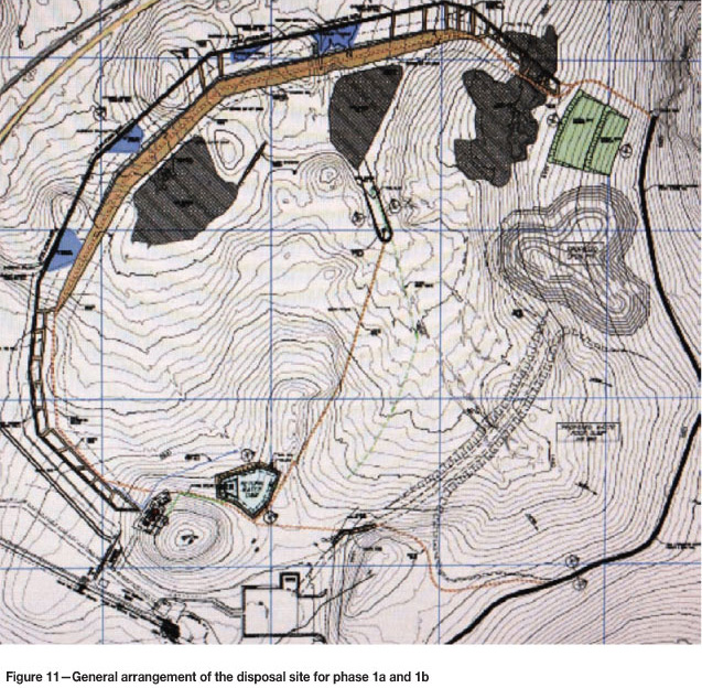
The disposal site and management plan7
The general arrangement of the disposal site as initially conceived is illustrated in Figure 11.
The PDF basin was three-dimensionally modelled for an accurate determination of the relationship between the height, area, and capacity. The detail was processed to calculate the rates of rise for average production rates and eventually the life of the PDF according to the following criteria:
The facility has been designed as an impoundment (compacted earth embankments) into which the tailings stream is deposited. The construction is phased, with the facility being built to accommodate the phased tonnage expansions using waste rock and overburden. Open-pit mining of an orebody (King Pit) located within the footprint of the facility ultimately provides additional capacity.
The initial beach slope flume tests from the Beeshoek pilot plant work were used to predict the beach slope and height of the outer wall.
The phase 2 expansion to 16 Mt/a of product required the facility to accommodate the mining activity within the King Pit located within the greater tailings footprint. For this expansion it was necessary to compartmentalize the dam into three compartments as detailed in Figure 12.
Supernatant and rainwater on the dam is removed by means of a penstock to the return water dam; the harvested water is recycled to the primary thickener along with the paste thickener overflow and is used in the primary plant operations.
Clean water runoff arising from the external catchment will be prevented from flowing onto the PDF and consequently becoming contaminated. In order to divert the flows from each portion of the catchment, cut-off trenches and diversion bund walls are included in the design.
Results
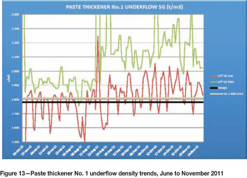
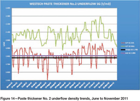
The graphs in Figures 13 and 14 show daily average results of the discharge underflow density for the six months from June through to November 2011 for the two paste thickeners. Both units are operating very consistently at or above the design underflow discharge density and within the design envelope, and this has clearly contributes to the overall water balances and successful operation of the PDF.
Deposition slopes are being maintained at 1 to 2 degrees in line with the design, with measured yield stresses at the deposition site ranging from 30 to 50 Pa. Unsheared yield stress values measured at the suction side of the thickener proving loop range from 100 to 200 Pa, although at times values approaching 300 Pa have been measured.
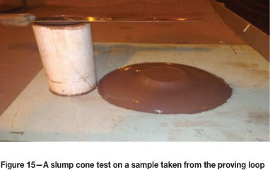
A slumlp cone test on a sample from the proving loop (Figure 15) showed a measured density of 2.04 t/m3 and an unsheared yield stress of 105 Pa, no bleed water was observed.
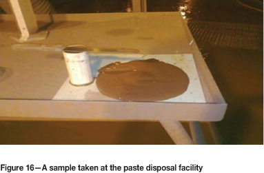
A similar sample taken at the PDF point has a density of 2.00 t/m3, but due to shear thinning through the multistage discharge pumping system and a small quantum of gland service dilution now exhibits a yield stress of just over 30 Pa (Figure 16).
Summary
The following aspects were to key to the successful design and implementation of the PDF and water management system at Khumani Mine:
In summary through an integrated design philosophy, and sound engineering practice and implementation, it is possible to successfully build and operate a wet processing iron ore operation in an arid environment, with water consumptions of 0.43 to 0.69 m3/t deposited on the PDF.
Conclusions
A water recovery and paste disposal system has been successfully implemented at Khumani Iron Ore Mine.
Although a water consumption of below 0.09 m3/t of product was achieved during phase 1a, the current water consumption is between 0.11 to 0.16 m3/t of product. However, these figures are perhaps a misrepresentation of the success of the operation, since increased ROM due to a higher plant utilization perhaps skews the figures when represented in this manner. The success is perhaps better represented by water losses in m3/t of solid deposited on the PDF. In this instance, values between 0.69 to 0.43 m3/t are being achieved.
Further refinements to reduce raw water intake are planned for 2012. These include a new treatment of the primary thickener overflow through a buoyant media clarifier to save on gland service water consumption, which should see a further 180 m3/h reduction in raw water consumption.
The project continues to produce a wealth of knowledge on optimizing and reducing raw water intake in wet processing iron ore plants, and the authors believe it sets a new benchmark in the industry as we strive to balance the needs of industry with limited natural resources such as clean raw water.
Acknowledgments
The authors would like to thank the management of Assmang's Khumani mine for permission to publish this paper.
References
1. Houman, J. and Johnson, G. Commissioning and Operatio n of the paste thickening farm at Kimberley Combined Treatment. Proceedings of International Seminar Paste and Thickened Tailings (Paste) Melbourne Australia 14-16 May Section 12. 2003. [ Links ]
2. Paste Thick and Associates (Pty) Limited. Pilot plant and geotechnical flume tests internal feasibility study on BKM tailings. January 2005. [ Links ]
3. Du Toit, T. BKM Internal Feasibility Study Report: Metallurgical Test Work & Interpretation. November 2005. [ Links ]
4. De Swart, G. Functional description for new paste disposal facility (BKM project). Report No. 6 T-04 /2007. Report to ECMP (Pty) Limited. April 2007. [ Links ]
5. Du Toit, T. Khumani Iron Ore Mine BkM project process description. Internal report. 25 June 2010. [ Links ]
6. Patterson and Cooke Consulting Engineers. BKM Residue pumping System: Design Description and Costing Document. Document PST-677.R07 Rev 2. June 2005. [ Links ]
7. De Koning, L. Paste disposal system design criteria document. Report No. ECMP!T1020- 1. October 2009. [ Links ]
8. Cooper, R.A. and Smith, M.E. Case study operations of three paste disposal facilities. Proceedings 14th International Seminar on Paste and Thickened Tailings (Paste2011), R.J. Jewell and A.B. Fourie (eds.), 5-7 April 2011, Perth, Australia, Australian Centre for Geomechanics, Perth. 2001. pp.261-270. [ Links ]

