


Services on Demand
Article
 English (pdf)
 Article in xml format
 Article references
Indicators

Related links
-
 Cited by Google
 -
 Similars in Google
Share

 Permalink
Journal of the Southern African Institute of Mining and Metallurgy
On-line version ISSN 2411-9717
Print version ISSN 2225-6253
J. S. Afr. Inst. Min. Metall. vol.111 n.11 Johannesburg Nov. 2011
TECHNICAL NOTE
An analytical solution to predict axial loadalong fully grouted bolts in an elasto-plastic rock mass
H. Jalalifar
Department of Petroleum and Mining Engineering, Environmental and Energy Research Center, Shahid Bohanar University of Kerman-Iran
SYNOPSIS
Nowadays, fully encapsulated rockbolts have become a key element in the design of ground control systems. The main reason is that they offer high axial resistance to bed separation. In this research, the load transfer capacity of a fully grouted bolt is evaluated analytically in an elasto-plastic rock mass condition. The research considered the effect of bolt end-plate on load transfer capacity. Bolt and surrounding materials were assumed to be elastic and elastoplastic materials respectively. The load transfer mechanism of a fully grouted bolt is a function of parameters such as bolt length, shear stiffness of interfaces, in situ stress, presence of face-plate and distance along the bolt. These factors were analytically evaluated. Finally, the load along the bolt was predicted in different surrounding rock mass characteristics.
Keywords: fully grouted bolt, axial load, elastoplastic, analytical, numerical-load transfer.
Introduction
The interface shear stresses, rather than the grouting material itself, are of great importance in the overall resistance of a rockbolt system. There are limitations to pull tests in determining the resistance of interfaces, as stress distribution in the system is affected by the geometry of the bolt, borehole, and the embedment material properties. The characterization of the bolt surface has major effect on the load transfer capacity of a fully grouted bolt, because surface roughness dictates the degree of interlocking between bolt and resin.
In this research, to define the load developed along the bolt, an analytical model of a bolt embedded in elasto-plastic rock mass conditions was developed. The model was evaluated both with and without an end-plate. Finally, different surrounding rock characteristics were entered in the model and load transfer capacity along the bolt was predicted.
Load transfer capacity
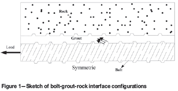
During rock movement, the load is transferred from the bolt to the rock via the grout by the mechanical interlocking action between surface irregularities at the interfaces. When axial shearing occurs during rock movement, the load is transferred to the bolt as the grout interface shears1. The ability to transfer the load between bolt, grout, and rock depends on grout annulus, grout strength, bolt profile characteristics, the roughness and strength of the rock, and mechanical properties of the bolt.
Slippage may occur at the rock/grout or grout/bolt interfaces, both being called decoupling. De-coupling takes place when the shear stress exceeds the strength of the interface. Failure in a laboratory test usually occurs along the bolt/grout interface. However, if rock, instead of a steel tube, is used as an outer casing element, then the failure may occur along the rock/grout interface, depending on the strength of the rock. If the rock is soft then failure occurs along the grout/rock interface because the mechanical interlock breaks down at low loads and frictional resistance comes into account. In hard rock the mechanical interlock would be dominant. Kilic2 reported that when the surface friction of a borehole decreases, slippage occurs at the grout/rock interface, and when the length of the bolt and borehole exceed a critical length for a 21 mm diameter bolt in a 27 mm diameter hole, failure takes place at the bolt. This has been demonstrated by laboratory tests3. Figure 1 shows the schematic representation of load transfer generated at the interface together with the bolt profile configuration. This shows that mechanical interlocking occurs when irregularities move relative to each other (wedges are created).
During shearing, surface interlocking will transfer the shear forces from one element to another. When the shear forces exceed the maximum capacity of the medium, failure occurs and only frictional and interlocking resistance will control the load transfer characteristics of the bolt. Effective bonding between bolt, resin, and rock can be attributed to adhesion, friction, and mechanical interlocking, but their relative importance depends on the test conditions. Adhesion is normally almost negligible, and this was clearly demonstrated by sawing a column of resin block cast on a bolt along the axis. Each section of resin detached cleanly from the bolt with the force applied, which was also supported by the results of bolt/resin shearing tests carried out under constant normal stiffness4. Bonding strength is almost zero when normal stress is reduced. It should be noted that friction also depends on surface roughness. It is obvious that the confining pressure applied has a major influence on the level of friction and interlocking action at the bolt-resin interface. Kaiser et al.5 reported that a mininginduced stress change is one of the most important parameters controlling bond strength.
Bond failure mechanism
When an axial load is applied to a bolt, it stretches longitudinally and contracts laterally because of Poisson's effect. When contraction occurs the bond breaks at the interface. Stretching and contracting is calculated in both pull and push tests during loading.
In pull and push laboratory tests, slip and yield occurred at the bolt/grout interface and the bolt did not fail internally6. For a bolt to undergo necking it must be gripped firmly at both ends, but pulling a bolt reduces its diameter longitudinally, resulting in contraction according to Poisson's effect, which would obviously affect its load transfer capacity. Debonding and reduction occur after the load-displacement curve has risen linearly. Based on the numerical analysis of6, there is a high level of load induced in the head, which reduces exponentially along the length. Increasing the load propagates the de-bonded area further along the bolt and expands it proportionally. From here the load decreases and the hinge point in the curve (load-displacement), called the maximum bearing capacity, is formed. After the peak point of the shear load, shear displacement depends on interlocking phenomena, which are a function of the profile specifications, resin grout properties, and resin thickness.
Analysis of an elastic bolt surrounded by plastic rock mass
The load transfer mechanism of a fully grouted bolt is a function of the surface condition, because surface roughness dictates the degree of interlocking between bolt and resin. The shear stress at interfaces, rather than of the grouting material, is of great importance in the overall resistance of a rock bolt system.
In modelling a single dimensional resin grouted anchor, Farmer7 advanced a theoretical solution for a circular elastically anchored bar surrounded by an elastic grout confined in a rigid borehole. He derived a homogeneous linear differential equation describing the distribution of the force along the anchor. The decay function was exponential in form. Pull tests on concrete, limestone, and chalk yielded different results. Good correlation was obtained in concrete under low axial loads, but in weaker limestone and chalk the results were inconsistent. Farmer also found the shear stress in the resin annulus was a function of the resin grout.
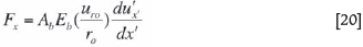
Following Farmer7, the equilibrium of a fully grouted rockbolt may be written:
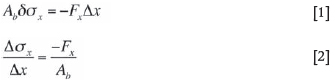
where;
Abis the bolt cross-section area
Fx is the shear load due to the bond per unit length under elastic behaviour conditions.
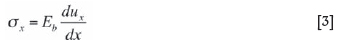
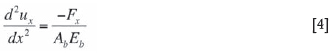
Then substituting [3] into [2]:
In other words, the shear force due to the bolt can be assumed as a linear function of the relative slip between the bolt and the rock8.
Then,

where:
K = shear stiffness of the interface (N/mm2)
ur= rock displacement along the bolt (mm), which decreases with distance from the surface of the excavation and depends on various in situ parameters such as, initial stress, rock mass modulus, bolt length.
By combining [5] and [4] the following equation for a distribution of displacement along the bolt was obtained.
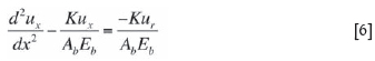
Moosavi8 used Equation [6] for analysis of cable bolts, but he considered both bolt and rock mass in an elastic state. In this model the bolt and the rock mass are considered as elastic and elasto-plastic respectively.
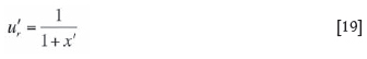
In the above equation, ur can be represented by an analytical function of the geometry of the tunnel and rock surface movement.
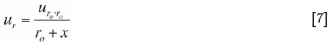
where
ro= tunnel radius.
urois the total deformation of the excavation wall, and is written as9
Parameters b, k, and f can be found from following Equations [9].

where
ν = Poisson ratio of rock mass
Po = in situ stress
c = cohesion
φ = friction angle
re= the boundary between the zone of plastic and elastic deformation
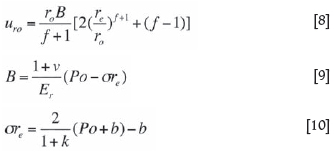
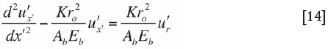
By combining Equation [8] into Equation [7] and then Equation [7] into Equation [6] and solving, the following numerical method has been developed. It is noted that the numerical method was used as a powerful tool to solve the developed analytical model.
In this case the bolt was divided into equal parts, and then the load distribution can be obtained by linking these small sections together. Thus to solve the reference equation (Equation [6]), dimensionless quantities are defined.
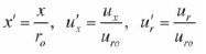
This can be written as;
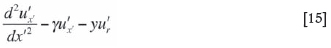
 is a dimensionless quantity. By defining γ =
  it can be written as,
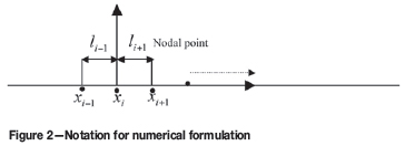
By dividing the bolting to n equal sections (Figure 2), and defining Δx' = x'i+1 -x'i = L/(nro), the expressions for the derivatives of u'x' at x' = xi' are given as
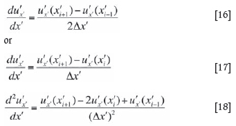
Equation [15] for i = 2, • • •, n can be written as;

These n-1 equations with two boundary conditions will form a tri-diagonal system of n + 1 linear algebraic equations with n + 1 unknowns, {u'x' (xi' )}, thus we have
A bolt under tension compresses the rock, which prevents bed separation and frictional forces developing between the layers, but this does not mean that more tension creates better stability10. When a bolt is pre-tension loaded it would influence the shear strength of the joint with forces acting both perpendicular and parallel to the sheared joint by inducing confining pressure. A general rule for determining maximum pre-tension is that it should not exceed 60% of the bolt yield strength or 60% of the anchorage capacity13. In this research the following two cases are examined;
Case 1-Bolt installed without face plate Fx= 0 at x = 0 and Fx= 0 at x = L
where
Defining the normalized force Fx' = Fx/ (AbEb), the above boundary conditions will be equivalent to:

or u'x' (x'1) = 1 and u'x' (x'n+1) -u'x' (x'n) = 0
The load developed along the bolt in both the above cases was analysed and following results were obtained.
Case 1: Bolt without face-plate
Figures 3 to 8 show the distribution of axial load developed along the bolt and normalized displacement, without a faceplate, installed in surrounding plastic materials. Three different bolt lengths, namely 2.1 m, 5 m, and 10 m were used for the analyses. The results are in agreement with the findings of Tang et al.11, who applied a generalized finite element technique. The input data for the surrounding materials are used according to Strata Control Technology's report12. The initial stress and rock modulus of elasticity are considered to be 25 MPa and 15 000 MPa respectively. Figure 3 shows the axial load profile along the bolt in different lengths. With increased length, the axial load is increased and also the peak point of the load moves towards the end of the bolt. In addition, the load is concentrated near the excavation surface. Figure 4 shows the normalized displacement as a function of bolt length. It shows that with an increase in length, displacement of rock is reduced.
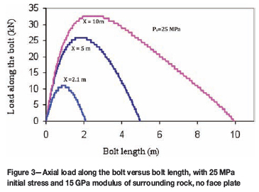
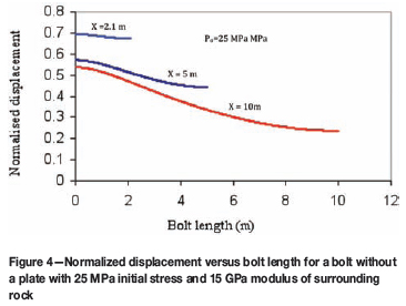
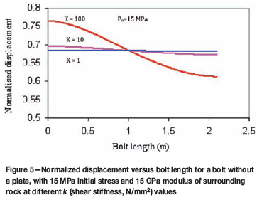
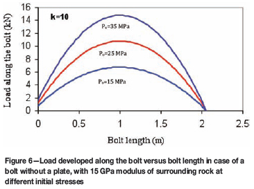
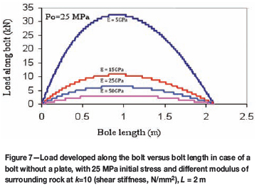
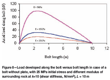
Figure 5 shows normalized displacement as a function of length for a 2.1 m bolt, in 15 MPa initial stress and with different interface shear stiffness values. It can be seen that, with an increase in interface stiffness, displacement is reduced. Using Equations [8] to [10], the value of uro in 15 MPa and 25 MPa initial stress is 6.3 mm and 10 mm respectively.
Figure 6 shows the load developed along the bolt increasing with an increase of initial stress at a constant stiffness. Figures 7 and 8 show load distribution along the bolts 2.1m and 10 m long respectively at 25 MPa initial stress for different values of rock modulus of elasticity. It shows that softer rocks generate higher load along the bolt. From the figures it is noted that the maximum load developed along the bolt is close to the bolt face-plate in the long bolt and almost centralized in normal length (2 m), which is in agreement with the field results and bolts installed in jointed rocks. When rockbolts are installed in the tunnel, the load generation initiates at the bolt/grout/rock structure. The full length of the bolt can experience loading. In reality, when adjacent rock blocks are sheared, due to joint roughness dilation occurs and this generates tensile forces in the bolt.
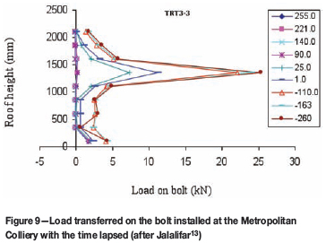
The results obtained from the analytical developed model were verified with the results obtained from the field investigation as shown in Figure 913. The load developed on the bolt is with respect to the retreating longwall face positions. For example, the load developed long the bolt was monitored from the initial longwall position 255 m ahead of the site to when the longwall face passed the site by 260m. As Figure 9 shows, the maximum load is approximately at the middle of the bolt, when the bolt is installed through the roof, which verifies the developed analytical approach.
Case 2: Bolt with face-plate
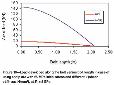
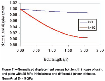
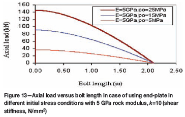
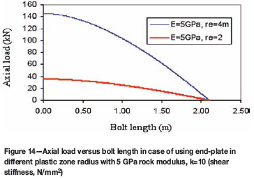
Using Equation [17] and boundary conditions in case 2 (using an end-plate), the axial load built up along the bolt and distribution of the bolt interface displacement for different bond strength, rock mass modulus of elasticity, and bolt length in various initial stresses were analysed. Figures 10 and 11 show respectively the axial load and distribution of the bolt displacement in two different bond stiffness conditions. It can be seen that the bond has significant influence on the development of load along the bolt length and the displacement. Figure 12 shows the distribution of axial load for different values of rock modulus and different bolt lengths. It shows that a higher rock modulus of elasticity generates a lower axial load along the bolt. This trend decreases exponentially towards the bolt end for both bolt lengths. Figure 13 shows the axial load distribution along the bolt in different initial stress conditions. It reveals that the surrounding rocks with higher initial stress induce a higher axial load along the bolt. As Figure 14 shows, the axial load reduced with decreasing radius of the plastic zone around the tunnel.

Conclusion
From the axial load developed along the elastic bolt surrounded by elasto-plastic materials in a circular tunnel, it can be inferred that bond strength, rock mass modulus, and initial stress have a significant affect on the load distribution level. Also, when a bolt is not anchored at both ends, the peak maximum axial load appears in the middle of a bolt 2.1 m in length. However, increasing the bolt length shifts the peak position closer to the surface of the excavation.
From the above both cases analyses, it can be inferred that:
References
1. SERBOUSEK, M.O. and SIGNER, S.P. Linear load-transfer mechanics of fully grouted roof bolts. Report of Investigations 9135. US Bureau of Mines, Pittsburgh, PA, 1987. [ Links ]
2. KILIC, A. and ANIL, M. The effects of grout properties to the bolt capacity. 16th Mining Congress, Ankara Turkey, 1999. pp. 189-196. [ Links ]
3. AZIZ, N. Bolt surface profiles- an important parameter in load transfer capacity appraisal. Proceedings of the Fifth International Conference on Ground Control and Mining Construction, Perth, Australia. 2004. [ Links ]
4. AZIZ, N. A new technique to determine the load transfer capacity of resin anchored bolts. 3rd Australian Coal Operators Conference, Wollongong, NSW, Australia, 2002. pp. 176-185. [ Links ]
5. KAISER, P.K., YAZICI, S., and NOSE, J. Effect of stress change on the bond strength of fully grouted cables. International Journal of Rock Mechanics and Mining Sciences & Geomechanics Abstracts, vol. 29, no. 3, 1992. pp. 293-306. [ Links ]
6. AZIZ, N. and JALALIFAR, H. Investigation into the transfer mechanism of loads in grouted bolts. Australian Geomechanics, vol. 40, no. 2, 2005. pp. 99-113. [ Links ]
7. FARMER, I.W. Stress distribution along a resin grouted rock anchor. International Journal of Rock Mechanics and Mining Sciences & Geomechanics Abstracts, vol. 12, 1975. pp. 347-351. [ Links ]
8. MOOSAVI, M. Load distribution along fully grouted cable bolts based on constitutive models obtained from modified Hoek cells. Ph.D.thesis, Faculty of Mining Engineering, Queen's University, Ontario, 1997. 287 pp. [ Links ]
9. STILLE, H., HOLMBERGE, M., and NORD, G. Support of weak rock with grouted bolts and shotcrete. International Journal of Rock Mechanics and Mining Sciences & Geomechanics Abstracts, vol. 26, no. 1, 1989. pp. 99-113. [ Links ]
10. PENG, S. and GUO, S. An improved numerical model of grouted bolt-roof rock interaction in underground openings. International Symposium on Rock support in Mining and Underground Construction, Sudbury, Ontario, Canada, 1992. pp. 67-74. [ Links ]
11. TANG, B., MITRI, H.S., and BOUTELDJA, M. Finite element modelling of rock anchors. Journal of Ground Improvement, vol. 4, no. 2, 2000. pp. 65-71. [ Links ]
12. TARRANT, G. Assessment of support requirements associated longwall reorientation. Report No. MET2431. Strata Control Technology, Wollongong, NSW, Australia, 2001. 30 pp. [ Links ]
13. JALALIFAR, H. A new approach determining the load transfer mechanism in fully grouted rock bolts. PhD Thesis, University of Wollongong NSW, Australia, 2006. [ Links ] ♦
Paper received Jul. 2009; revised paper received Jul. 2011.
© The Southern African Institute of Mining and Metallurgy, 2011. SA ISSN 0038-223X/3.00 + 0.00.

