


Serviços Personalizados
Artigo
 Inglês (pdf)
 Artigo em XML
 Referências do artigo
Indicadores

Links relacionados
-
 Citado por Google
 -
 Similares em Google
Compartilhar

 Permalink
Journal of the Southern African Institute of Mining and Metallurgy
versão On-line ISSN 2411-9717
versão impressa ISSN 2225-6253
J. S. Afr. Inst. Min. Metall. vol.111 no.10 Johannesburg Out. 2011
TRANSACTION PAPER
Mathematical modelling of heat transfer in six-in-line electric furnaces for sulphide smelting
Y. Pan; S. Sun; S. Jahanshahi
CSIRO Process Science and Engineering, CSIRO Minerals Down Under National Research Flagship, Clayton South, Australia
SYNOPSIS
An efficient and portable mathematical model has been developed for simulating heat transfer in six-in-line slag-resistance-heating electric furnaces for smelting sulphide ores to produce base metals and platinum group metals. This model is a steady-state one relating furnace conditions and performances to various control and input parameters. Some transient effects occurring in electric furnaces are neglected for computation efficiency. This article describes the model development and modelling results. The present model is capable of predicting: (i) temperatures at various locations in a six-in-line furnace, such as slag bath, matte bath, solid charge, freeboard space, freeze lining, cooling water, and air gaps between solid material components, etc. (ii) freeze lining thickness, (iii) smelting rate, and (iv) heat loss rate, etc. A typical feature of the model is that it is easily portable to different application platforms and sufficiently efficient with execution times less than a few seconds. Therefore, it is possible to apply the model for online prediction and control of heat transfer and freeze lining thickness in industrial electric furnaces.
Keywords: electric furnace, six-in-line furnace, smelting, heat transfer, freeze lining.
Introduction
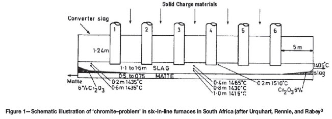
Slag-resistance-heating electric furnaces, either rectangular in shape with six electrodes in line (six-in-line furnace for short) or circular in shape with three electrodes in delta (three-electrode furnace for short), are commonly used for producing base metals and platinum group metals (PGMs). (For simplicity in terminology, we call all of them electric furnaces). However, due to ever-deteriorating quality of feed materials, especially ore concentrates, together with process intensification through increasing electric power input, the furnaces have to withstand more and more challenging operating conditions, leading to elevated furnace temperatures and unstable furnace operations and integrity. In South Africa, for instance, electric furnaces are widely used for smelting sulphide ores to extract base metals and, in particular, the PGMs. As the output of low Cr2O3 (< 1 wt.%) concentrate from the Merensky ore body becomes increasingly tight, the South African PGM producers tend to rely, at least partly, on the UG2 ore, which contains higher levels of Cr2O3 (about 5 wt%) 1. The high Cr2O3 content in the feed causes serious operational problems in the electric furnaces1,2. Cr2O3 in slag can form spinels with high melting points, leading to more viscous slag that is difficult to control. According to Urquhart et al.3, Cr2O3 can precipitate as spinel particles in lowtemperature regions close to both ends of electric furnaces (no. 1 and no. 6 electrode cells), as shown in Figure 1. If the slags are highly viscous, more PGMs, along with matte droplets (prills), may be trapped in the slags. These issues force the operator to run the furnaces at higher temperatures, which not only adds to the cost for consumption of electricity and refractories, but also results in unstable furnace integrity by destablizing the freeze lining. Moreover, as shown in Figure 1, the spinel phases rich in Cr2O3 tend to lie between the matte and slag layers, which causes electric conduction problems1,3, lowering the heating efficiency of the electric furnace.
Process intensification by increasing the power input is often used to maintain high productivity. However, this can lead to operational problems, such as low lining life and cooling unit life due to unstable freeze linings, etc. To keep electric furnaces robust under the changing operating conditions and with the degrading quality of raw materials, it is necessary to find out effective and efficient ways to solve these problems. One possible low-cost solution is the development of simulation tools such as mathematical models that can be conveniently used to efficiently control and optimize the heating process of the electric furnaces so as to maintain smooth, efficient and low-cost furnace operations.
A survey of the literature revealed that mathematical modelling research on heat transfer and fluid flow (with or without coupling of electric fields) in electric furnaces is not extensive, and there are only a few mathematical models available, most of which are based on computational fluid dynamics (CFD) or magnetohydrodynamics (MHD) modelling techniques4-8. While these sophisticated models can offer detailed predictions of the fluid flow, heat transfer, and electric fields in the furnaces, they require high computational power to run. Consequently, these models have been used to simulate only portions of an electric furnace, not an entire furnace. Furthermore, they are generally slow to converge and, thus, are inadequate for potential online implementation. Most of the CFD and MHD models require commercial software for implementation, which limits their portability on different application platforms (e.g. furnace control rooms). On the other hand, online predictive models for whole electric furnaces are desperately needed for the industries to stabilize their furnace operations and increase campaign lives. Therefore, alternative models that can simulate the entire furnace and are efficient and portable with a potential for online implementation are necessary, and should be developed to aid the operators obtain timely prediction of performance and better control of their electric furnaces.
The aim of the present work is to develop such models based on alternative mathematical approaches. We expect the models should simulate heat transfer in the whole furnace and should possess the following capabilities:
Prediction of temperatures at various locations in an electric furnace (such as slag bath, matte bath, freeze lining, solid charge, cooling water, freeboard space, air gaps, and various material interfaces, etc.)
The current version of the model is a steady-state one. It allows the evaluation of the impact of changing operating parameters on the steady-state conditions of the furnace. The transient behaviour is not yet fully accounted for.
Heat transfer model development
Model principle
In the present work, the heat transfer model was established based on the principle of heat balances in the furnace media (slag, matte, solid charge, and off-gas) and the concept of thermal resistances-in-series for heat transfer in the furnace wall, bottom, and roof, which are comprised of multilayer composite materials. Applications of this principle to the development of heat transfer models for both six-in-line and three-electrode furnaces have been reported elsewhere9. The present article describes, in detail, the model development for simulating heat transfer in six-in-line furnaces.
Assumptions
In the present heat transfer model, the following modes of heat transfer and heat exchange are considered to take place in electric furnaces:
In order to mathematically model the abovementioned heat transfer phenomena in electric furnaces, some general assumptions are made:
The assumption of uniform dissipation of the heat into the whole volume of the slag bath obviously misses the fact that the slag close to the electrodes is hotter than the rest of the slag bath due to non-uniform current distribution, for instance. Further model refinement in this area will be considered in future work.
Furnace geometry and material configuration
Figure 2 schematically illustrates the model representation of a six-in-line furnace. As indicated, the furnace is geometrically considered as an assembly of a number of cells, separated by hypothetical planes shown by the dashed lines in Figure 2. Each cell has one electrode and is termed an electrode cell. Thus, a six-in-line furnace is comprised of six electrode cells. The slag tapholes are assumed to be located in the end wall of no. 6 electrode cell, whereas the matte tap holes are in the end wall of no. 1 electrode cell. The off-gas uptakes are assumed to be located at both ends of the electric furnace. For simplicity, the tapholes and material charging holes (in the furnace roof), as well as off-gas uptakes, are not shown in Figure 2. In addition, the outer surface of the furnace bottom steel shell plate is assumed to be cooled by forced air convection at a uniform velocity of, for example, 10 m/s. By taking advantage of mirror symmetry in geometry about the central vertical plane along the longitudinal direction of the furnace (A-A plane in Figure 2(b) ), only half of the furnace is considered in the heat transfer model.
Figure 2 also depicts the furnace material configuration. According to this figure, each electrode cell consists of the following material components:
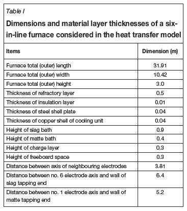
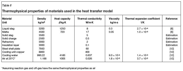
Table I gives, as an example, material dimensions and configurations of a six-in-line furnace simulated by the present heat transfer model, and Table II lists the thermophysical properties of the materials used by the heat transfer model.
Smelting zone
In electric furnaces, the smelting zone is the region where solid charge materials are smelted, at a fixed temperature depending on the chemistry of the charge materials, into liquid slag droplets, liquid matte droplets, and reaction gases. It is generally a thin layer between liquid slag bath and solid charge layer. The characteristics of this zone were described by Sheng et al. for nickel smelting 6. In the present modelling work, we define the interface between slag bath and solid charge as the smelting zone, as indicated in Figure 2(a).
Bulk material flows
Figure 3 schematically depicts the defined flow directions of the bulk fluids, such as liquid slag, liquid matte, gaseous products due to smelting (reaction gases), and ingress air as well as off-gas. As indicated, the slag droplets produced in the smelting zone immediately join in the slag bath and exchange heat with it; the matte droplets produced in the smelting zone first pass through and exchange heat with the slag bath, and then enter the matte bath and exchange heat with the matte bath; and the reaction gases generated in the smelting zone flow upward through the porous solid charge layer, exchange heat with it and then enter the freeboard space where they meet with the ingress air to form the offgas.
Furthermore, as seen from Figure 3, the bulk slag flows in the longitudinal direction toward the slag tap end of the furnace while, as an assumption, the bulk matte flows in the opposite direction toward the matte tap end of the furnace at a rate corresponding to the average production rate. (It should be borne in mind that, in practice, for six-in-line furnaces the slag is normally tapped continuously but the matte normally tapped periodically in batches, resulting in some transient effects due to the gradual increase of matte bath volume.) The hot reaction gases evolving from the solid charge mix with the cold air infiltrating through the furnace roof (via charging holes and electrode holes, etc.) to form the off-gas, which flows in opposite directions toward the uptakes, which are assumed to be located in both ends of the furnace.
Mathematical formulation
General heat balance equation
In the present modelling work, at steady state, a general heat balance equation for a bulk material (slag bath, matte bath, solid charge layer or off-gas above the solid charge layer) in an electrode cell of a six-in-line furnace can be written as
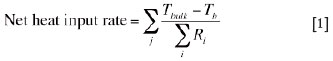
where, Tbulk is the average temperature of a bulk material in question (such as slag, matte, solid charge or off-gas) ; Tb is the boundary temperature; j denotes the direction of heat transfer; i stands for a material layer involved in the electrode cell; and Ri is the thermal resistance of the ith material layer or the interface between this material layer and the fluid flowing over it.
The right-hand side of Equation [1] is a general representation of the rate of heat lost, in different directions indicated by j, to the atmosphere or to the cooling water, in which Tb is defined as below:
(1) For heat losses from the slag bath to the cooling units, Tb is the inflow cooling water temperature
(2) For heat losses from a bulk material to the atmosphere, Tb is the atmosphere (room) temperature.
Equation [1] states that at steady state a net heat input into a bulk material in an electrode cell dissipates through the bounding materials to the atmosphere and cooling water. Based on Equation [1], heat balance equations for the individual bulk materials can be easily derived. Examples are given in the following sections.
Heat balance in the slag bath
As shown in Figure 2, the slag bath is bounded by the matte bath below, the freeze lining in the sidewall, and the solid charge layer above. As mentioned earlier, the slag/charge interface is defined as the smelting zone where the solid charge is smelted into slag droplets, matte droplets, and reaction gases. Therefore, at steady state, a heat balance equation for the slag bath can be written as follows:
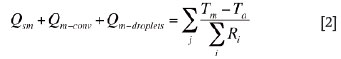
where, Qinput is the effective electric energy input rate (power) into slag bath in an electrode cell (W) ; Qs-conv is the net convection heat flow rate transported by the bulk slag flow from the neighbouring electrode cells; Qdroplets is the net sensible heat flow rate brought by the descending slag and matte droplets produced at the slag/charge interface (smelting zone) ; Qsc is the convection heat flow rate from the slag bath to the slag/charge interface; Qsm is the convection heat flow rate from the slag bath to the matte bath; Ts is the average temperature of the bulk slag in an electrode cell; and Tw,in is the temperature of the inflow water into cooling units.
The term on the right-hand side of Equation [2] stands for the heat flow rates through the sidewalls (in electrode cells nos. 2 to 5) or the side and the endwalls (in electrode cells nos. 1 and 6) from the slag bath, through the multilayer materials (i.e. freeze lining, copper shell of cooling unit, and, if any, air gap in between), to the cooling water. The heat loss through the outer copper shell of the cooling unit is ignored.
Heat balance in the matte bath
The matte bath is bounded by the refractory in the bottom and in the sidewall and by the slag bath on the top. At steady state, a heat balance equation for the matte bath can be written as
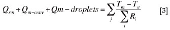
where, Qm-conv is the net convection heat flow rate transported by the bulk matte flow from the neighbouring electrode cells; Qm-droplets is the sensible heat flow rate brought by the matte droplets descending from the slag bath; Tm is the average temperature of the bulk matte in an electrode cell; and Ta is the ambient (atmosphere or room) temperature.
The term on the right-hand side of Equation [3] stands for the heat flow rates through the side and the bottom walls (in electrode cells nos. 2 to 5) or the side, the bottom, and the end walls (in electrode cells nos. 1 and 6) from the matte bath, through the multilayer materials (i.e. refractory, insulation layer, and steel shell plate) to the atmosphere.
Heat balance in the solid charge
The solid charge is bounded by the slag bath below, the refractory in the sidewall, and the freeboard space above. A heat balance equation for the solid charge layer can be written as
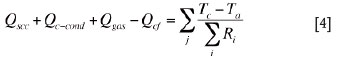
where, Qscc is the conduction heat flow rate from slag/charge interface to the centre of the solid charge layer; Qc-cond is the net conduction heat flow rate in the solid charge from the neighbouring electrode cells; Qgas is the net heat flow rate absorbed by the solid charge from the reaction gases generated by smelting at the slag/charge interface; Qcf is the convection and radiation heat flow rate from the top surface of the solid charge layer to the freeboard space; and Tc is the temperature at the centre of the solid charge layer in an electrode cell.
The term on the right-hand side of Equation [4] stands for the heat flow rates, in two directions (along the length and the width of the furnace), from the solid charge through the multilayer composite materials (i.e. refractory and steel shell plate) to the atmosphere.
Heat balance in the freeboard space
The freeboard space is enclosed by the solid charge below, the refractory in the sidewall, and the refractory in the roof. It is a volume filled with the off-gas formed by a mixture of the reaction gases (generated by smelting) and the ingress air (infiltrated from the atmosphere). A heat balance equation for the freeboard space reads:
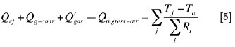
where, Qg-conv is the net convection heat flow rate transported by bulk off-gas flow in the freeboard space from the neighbouring electrode cells; Q'gas is the net heat flow rate transported by the reaction gases evolving through the solid charge layer into the freeboard space; Qingress-air is rate of heat absorbed by ingress air in the freeboard space; and Tf is the average temperature of the bulk off-gas in an electrode cell.
The term on the right-hand side of Equation [5] stands for the heat flow rates from the freeboard space to the atmosphere through the sidewalls and the roof. In addition, a fixed volumetric flow rate of the ingress air is introduced into each electrode cell.
In the present modelling work, we aim to solve Equation [1] or Equations [2] to [5], constrained by appropriate boundary conditions, to obtain the following results:
Calculation of the freeze lining thickness
Under the steady-state heat transfer condition, the thickness of the freeze lining layer can be calculated in a straightforward manner as follows
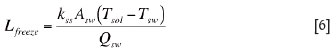
where, Qsw is the convection heat flow rate from the bulk liquid slag to the surface of the freeze lining layer; Tsol is the solidus of the freeze lining (i.e. solid slag), which is set to 132 K for nickel smelting6; Tsw is the temperature of the interface between the freeze lining layer and the copper shell of the cooling unit for perfect contact conditions, or the cold face temperature of the freeze lining layer if there is an air gap between the freeze lining and the copper shell of the cooling unit; kss is the thermal conductivity of the freeze lining; and Asw is the area of heat transfer between the freeze lining and the cooling unit.
Calculation of the furnace smelting rate
The electric furnace smelting rate is defined as the amount of solid charge that is smelted per unit time. This parameter is obtained based on the net rate of heat flow consumed for smelting and the heat required for smelting per ton of solid charge (defined as charge smelting heat), i.e.
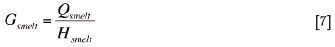
where, Gsmelt is the charge smelting rate in an electrode cell; Hsmelt the charge smelting heat (for nickel smelting, Hsmelt is evaluated to be 1.326 MJ/t, using the data reported by Sheng et al.6) ; and Qsmelt the net rate of heat flow consumed for smelting the solid charge, which is defined as the difference between the rate of heat flow supplied from slag bath to the slag/charge interface (i.e. smelting zone) and the rate of heat flow consumed for heating solid charge, slag and matte, and by conduction to the centre of the solid charge layer, i.e.

The heat flow rate from the slag bath to the smelting zone, Qsc, is calculated as
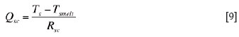
where Tsmelt is the smelting zone temperature, which is set to 1373 K for nickel smelting6; and Rsc the heat transfer resistance at the slag/charge interface, which is a function of heat transfer coefficient and area of the slag/charge interface.
The heat flow rate from the slag/charge interface by conduction to the centre of the solid charge layer, Qscc, is calculated as
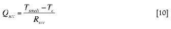
where, Rscc is the conduction heat transfer resistance between the slag/charge interface and the centre of the solid charge layer.
Qc is the rate of heat flow consumed for heating the solid charge to the smelting zone temperature:

where Cpc is the heat capacity of solid charge.
Qs is the rate of heat flow consumed for heating the newly produced slag droplets from the smelting zone temperature to the slag bath temperature:
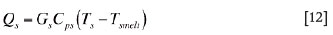
where Gs is the slag production rate and Cps the heat capacity of liquid slag.
Qm is the rate of heat flow consumed for heating the newly produced matte droplets from the smelting zone temperature to the slag bath temperature:

where Gm is the matte production rate and Cpm the heat capacity of liquid matte.
In the present modelling work, it is assumed that the smelting of solid charge generates mainly three forms of products, i.e. slag, matte, and gas. Based on unpublished mass balance calculations on smelting copper- and nickel-bearing sulphide ores, the weight fractions in percentages of slag, matte, and gas in the total smelting products are estimated to be 72.7%, 19.1%, and 8.2%, respectively. For PGM smelting, however, different mass balance calculations should be used to obtain such data.
The total furnace smelting rate is the summation of the smelting rates (Gsmelt) of all the six electrode cells in an electric furnace. Likewise, the total furnace heat loss rate is the summation, also over all the six electrode cells, of the heat loss rates through furnace bottom, wall, and roof to the atmosphere, through the freeze lining layer to the cooling water and through the solid charge layer to the off-gas flowing out of the furnace.
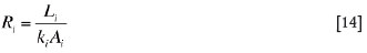
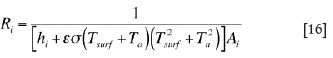
Calculation of the thermal resistances
The thermal resistance, Ri, involved in Equations [1] to [5] can be calculated as
(i) for a flat layer of solid material,
(ii) at liquid/liquid or liquid/solid interface (such as liquid slag/matte, liquid slag/solid slag, liquid slag/solid charge, matte/refractory, or cooling water/copper shell of cooling unit),
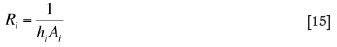
(iii) at steel shell plate/ambient air interfaces,
(iv) at solid/gas interfaces enclosing internal cavities (such as freeboard space and air gaps between layers of solid materials),
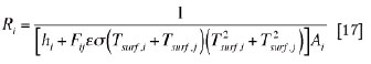
In the present heat transfer model, only the air gap formed between the freeze lining and the copper shell of cooling unit is considered, and the heat transfer by convection inside the air gaps is neglected. In addition, the radiation heat transfer through all condensed phases is also neglected.
Calculation of the heat transfer coefficients
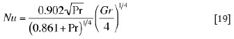
As seen from Equations [15] to [17], convection heat transfer coefficients are involved in the calculations of the heat transfer resistances of various liquid/liquid and fluid/solid interfaces. In the present model, we adopted corrected empirical dimensionless correlations to evaluate the heat transfer coefficients for various interfaces involving fluids, i.e.
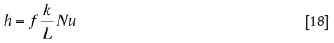
where, h is heat transfer coefficient; k is thermal conductivity L is a characteristic length of the interface; Nu is the Nusselt number; and f is a correction factor for each interface. (For clarity, in Equation [18] the material identity, i, as a subscript, is omitted.)
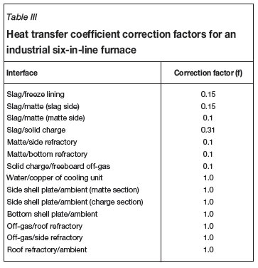
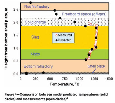
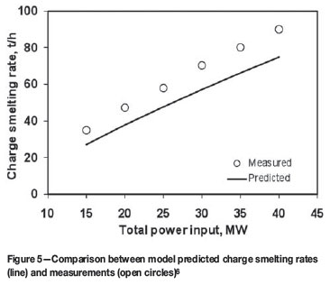
The heat transfer coefficient correction factor f should be evaluated using measured data (e.g. temperatures) on the electric furnaces to be modelled. As an example, Table III gives a set of f values obtained, based on published data6and by means of trial and error, for various interfaces in a production six-in-line furnace of Xstrata plc operated at Sudbury (formerly Falconbridge Limited), Ontario, Canada. By using this set of f values, a good match was obtained between the model-predicted temperatures vertically across the slag and matte baths and the measurements reported by Sheng and Irons6, as shown in Figure 4. In addition, based on the same set of f values, a reasonable agreement between the predicted furnace charge smelting rate, as a function of total furnace power input, and that reported by Sheng and Irons6was also reached, as shown in Figure 5.
The Nusselt number in Equation [18] is obtained from the following empirical dimensionless correlations based on natural convection flows10,11:
(i) for all vertical interfaces (e.g. interfaces between liquid slag/freeze lining, matte/sidewall refractory and sidewall shell plate/ambient air, etc.):
where Nu, Pr, and Gr are the Nusselt number, the Prandtl number and the Grashof number, respectively
(ii) for horizontal interfaces:
if the interfaces are hot and facing upward or cold facing downward (e.g. interfaces between liquid slag/solid charge, and roof refractory/ambient air, etc.)

or

If the interfaces are hot and facing downward or cold facing upward (e.g., interfaces between slag/matte and matte/bottom refractory, etc.):

(iii) for interfaces where only forced convection applies, the following dimensionless correlations, derived from reference13, are employed:

or

where Re is the Reynolds number.
Heat transfer in the cooling unit
For heat transfer in water cooling units, special treatments were made for evaluating the heat transfer resistance between copper shell and water and the relevant convection heat transfer coefficient. In the present modelling work, the water cooling unit is assumed to be a wall made of a snakelike copper pipe with water running through it, as schematically illustrated in Figure 6. Based on the geometrical and material configurations shown in this figure, the overall thermal resistance for the interface between the copper shell (pipe wall) and water can be derived, by integration over the total length of the water pipe, as

The convection heat transfer coefficient between water and pipe wall is calculated as
where the Nusselt number is obtained from the following empirical dimensionless correlation10
Based on these equations, the temperature of water flowing out of the cooling unit can be calculated by using the following equation:
For the meanings of all the symbols involved in Equations [14] through [28], see the Appendix.
Modelling method, efficiency and model portability
In the present work, the heat transfer model was established by numerically solving Equation [1] or Equations [2] to [5]. Gauss-Seidel iteration method was used to obtain primary solutions Ts, Tm, Tc and Tf, together with various interfacial temperatures (e.g., Tsw and Tsurf, etc.), from which other parameters, shuch as freeze lining thickness and charge smelting rate, etc., can be calculated using Equations [6] and [7], respectively. The model was developed into an in-house computer program coded in DIGITAL Visual Fortran 90, which generates executables that can run in all personal computers with MicrosoftTM Windows®. The model can be executed both in a GUI and in a command line. In the case of using a GUI, a user-friendly Excel® spreadsheet was designed, using MicrosoftTM Visual Basic Scripts®, where all data input and output and execution of the program can be made. It saves input/output data in files of both XLS and TXT formats. Users can type in their input data in worksheets named in different categories like 'Furnace Dimensions' and 'Material Properties', etc. Then, the users can submit their input data (by pressing 'SAVE INPUT DATA' button), execute the model (by pressing 'RUN' button), check the results (by pressing 'OUTPUT RESULT' button), all in one Excel worksheet. Furthermore, some typical graphics/charts can be automatically generated in Excel for user's convenience and at user's choice, such as slag, matte, solid charge, and off-gas temperatures, freeze lining thickness, slag and matte production rates, etc. In addition, an online help function (accessed by pressing the 'HELP' button) was also designed should the users need help to use the model. Therefore, the model is easily portable and can be executed on a wide variety of computing platforms with Microsoft Windows with an Office suite including Excel. Moreover, the model is also sufficiently efficient, with execution times of less than a few seconds even on ordinary personal computers. Therefore, the model can potentially be applied online for prediction and control of the heating on production electric furnaces in industries.
Results and discussion
Predicted temperatures of slag and matte in a six-inline furnace
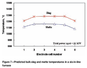
Figure 7 shows the predicted average temperatures in the slag and matte baths for each electrode cell of a six-in-line furnace. The furnace has a total power input of 22 MW. This electric power is uniformly distributed to the six electrodes. That is, each electrode cell receives 3.67 MW heating power. Under this condition, it can be seen from Figure 7 that the resultant average temperatures in the bulk slag and matte are non-uniform along the length of the furnace. The temperatures in the end electrode cells (i.e. no.1 and no.6 electrode cells) are noticeably lower than those in the middle electrode cells. The reason is self-evident in that, as depicted by Figure 2, the no. 1 and no. 6 electrode cells have larger volumes (and hence lower average power density) and more heat transfer surfaces (walls) than the middle electrode cells. This feature of the results is commonly found in practice and could be the major reason why chromite spinel precipitation normally appears at the ends of some electric furnaces operated in South Africa, as depicted by Figure 1.
Predicted temperatures of solid charge and off-gas in a six-in-line furnace
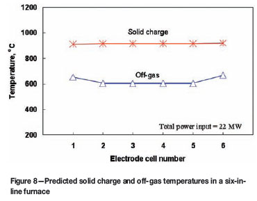
Figure 8 shows the predicted solid charge temperature and off-gas temperature in each electrode cell of a six-in-line furnace, corresponding to the slag and matte temperatures shown in Figure 7. It can be seen that, unlike the distributions of slag and matte temperatures, the solid charge temperature is quite evenly distributed along the length of the furnace. This is because, even though the slag temperatures in the end electrode cells are lower than those in the middle cells, the off-gas temperatures in these electrode cells are higher than those in the middle cells and, thus, the combined thermal effects of the slag bath and the off-gas lead to a nearly uniform temperature distribution in the solid charge layer along the length of the furnace. The reason why the off-gas temperatures in no.1 and no.6 electrode cells are higher than those in the middle cells is due to the assumptions that the off-gas uptakes are arranged in these cells and the same amount of leakage air is assumed for each electrode cell.
Predicted freeze lining thickness in a six-in-line furnace
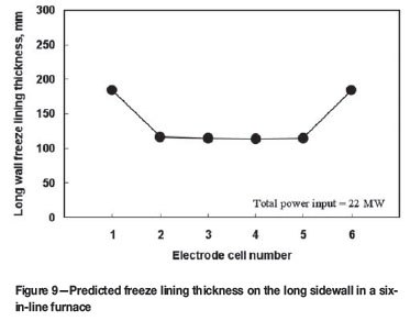
Figure 9 shows the predicted thickness of the freeze lining along the long wall of a six-in-line furnace under the same power input condition shown in Figures 7 and 8. We can see that the freeze lining thickness is closely related to the slag temperature distribution along the length of the furnace (c.f. Figure 7). The freeze lining is much thinner in the middle electrode cells than in the end electrode cells, because the slag temperature is higher in the former cells but lower in the latter cells. For very high power input or extreme bulk slag temperatures, more attention should be paid to the cooling in the middle electrode cells of electric furnaces. In addition, special flow and heat transfer conditions near the tapholes are obviously additional factors of importance.
Predicted smelting rate in a six-in-line furnace
The predicted smelting rate of solid charge as a function of the total power input was shown in Figure 5. For the purpose of model verification, the measured solid charge smelting rates reported by Sheng et al.6are also included in the figure for comparison, which indicate that the model underestimates the smelting rate to some extent depending on the power input, showing the discrepancies become larger for a higher power input. The reason for such discrepancies are: (i) a primary cause being that the results given in Figure 5 exclude the effect of coke combustion in the electric furnace investigated by Sheng et al.6, and (ii) a secondary cause being that, due to natural convection, a temperature gradient exists across the height of the slag bath, leading to a higher temperature in the vicinity of the smelting zone than the average temperature of the bulk slag. Thus, Equation [9] generally underestimates the heat flow rate (Qsc) to the smelting zone. Both factors are enhanced at a higher power input resulting in a larger discrepancy between the model predictions and the measurements.
Figure 5 also shows that the smelting rate increases nearly linearly with the increase of the power input. A 10 MW increase of power input will lift the smelting rate by about 20 t/h. This implies that the process intensification by increasing power input is an effective way to enhance productivity. However, as indicated by Figure 10, which is plotted based on the same data as shown in Figure 5, in terms of specific power consumption (i.e. total power input rate divided by total charge smelting rate), both predicted and measured smelting rates exhibit a minimum with respect to the power input. This demonstrates that there exists an economic range of power input, in which the lowest specific power consumption could be reached.
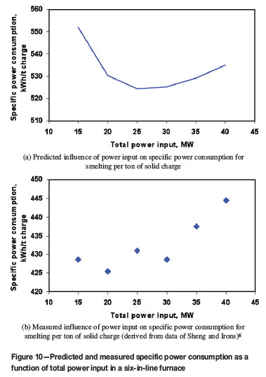
The reason for the existence of minimum specific power consumption could be two-fold: (i) in electric smelting processes, a minimum power input is necessary to keep the bulk slag temperature always above the smelting temperature (otherwise, no smelting would occur and thus the smelting rate would be zero), and (ii) the relationship between the smelting rate and the power input is not strictly proportional, but a slightly convex and monotonic-rise curve. The first factor dominates the downward trend at low smelting rates, while the second factor governs the rise in specific power consumption at high smelting rates. The second factor results from the non-linearity in the governing equations of heat transfer, i.e., Equation [1] or Equations [2] to [5], in which some thermal resistances are complex functions of temperature. Typically, as implied by Equations [19] to [22], the heat transfer coefficients computed by the present model are nonlinear functions of temperature. Since these two factors are intrinsic to all electric furnaces, it can thus be inferred that there is likely to be an economical range of power input, in which minimum specific power consumption could be realized. According to Figure 10, this economical power input range may be found to be 20-30 MW. Of course, applying such an economical power input doesn't guarantee a high productivity. Therefore, a compromise between productivity and specific power consumption, resulting in a net gain in profit, would be highly recommended in practice. The relationship between the power input and the specific power consumption will be further investigated in the future.
Predicted heat loss rate in a six-in-line furnace
Figure 11 illustrates the ratio (in percentage) between the total heat loss rate and the total power input as a function of the total power input for a six-in-line furnace. We can see from this figure that the total heat loss as a percentage of the total power input decreases with increasing of the power input. This suggests that at a high power input level a smaller fraction of the input power is lost to the surroundings. However, as indicated by Figure 10, this doesn't imply a more efficient utilization of the input energy for smelting, as a greater fraction of this energy is simply consumed for heating, leading to higher furnace temperatures.
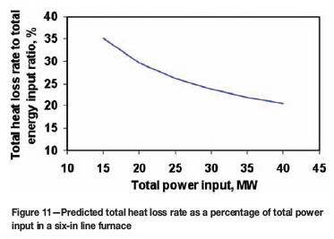
Figure 12 shows a break-down of the total heat loss into the sidewall, bottom, roof, off-gas and cooling water (in percentage of the total heat loss) in a six-in-line furnace. It can be seen from this figure that the furnace heat is mainly transported away by cooling water and off-gas. Of the total heat loss, for the total power input range (15-40 MW) investigated in this work, 35 to 45% is lost to the cooling water, about 33% to the off-gas, 10 to 15% through the furnace bottom and roof, and less than 5% through the refractory sidewalls (in contact with the matte bath and the solid charge layer). While the fractions of the total heat loss through the furnace bottom and refractory walls and to the off-gas all decrease with the increase of the power input, the fraction of the total heat loss to the cooling water increases with the increase of the power input. This demonstrates that at higher and higher power input levels, higher proportions of energy is consumed for simply heating the slag.
Influence of electric power input on slag temperature and freeze lining thickness
Figure 13 shows the predicted slag bath temperature, as a function of the total power input, in a particular electrode cell (no. 4 cell) in a six-in-line furnace. This figure indicates that there is a nearly linear relationship between power input and slag bath temperature. An increase in the power input by 10 MW will lift the slag temperature by 50 to 60ºC.
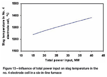
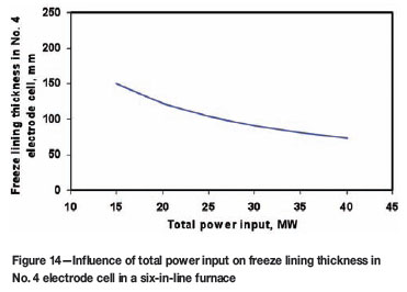
Figure 14 shows the model predicted freeze lining thickness, also as a function of the total power input, in the same electrode cell. It can be seen from this figure that the power input has a significant impact on the stability of the freeze lining. A higher power input leads to a thinner freeze lining. For instance, an increase of the power input by 10 MW can decrease the freeze lining thickness by 17 to 45 mm (or 20 to 30 per cent).
Influence of air gap formation on freeze lining thickness
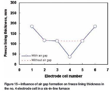
In the present work, two limiting contact conditions between different solid material components in electric furnaces are assumed: (i) perfect contact and (ii) complete air gap formation between the freeze lining and the copper shell of the cooling unit. In the model, air gaps appearing in sidewalls of any electrode cells can be taken into account. Figure 15 shows the predicted freeze lining thickness in the sidewalls of a six-in-line furnace. It is assumed that a complete air gap is formed between the freeze lining and the cooling unit in the sidewall of the no. 4 electrode cell, while perfect contacts are assumed for the sidewalls of all the rest of the electrode cells. We can see from this figure that, compared with other electrode cells, an air gap formation can cause a decrease in freeze lining thickness (due to remelting) by more than half of its original thickness. Thus, an air gap has a marked impact on the stability of the freeze lining and its formation could be one of the significant root causes for the failure of cooling units in electric furnaces.
Influence of cooling parameters on freeze lining thickness
Figure 16 shows the influences of cooling water flow rate and inflow water temperature on the freeze lining thickness in the no. 4 electrode cell. It can be seen from this figure that, below about 4 kg/s, the cooling water flow rate has a significant influence on the freeze lining thickness; above this value, however, the effect of cooling water flowrate diminishes. The inflow water temperature has a limited effect on the freeze lining thickness. A decrease of this temperature from 60ºC to 20ºC results in an increase of freeze lining thickness by only 4 to 5 mm.
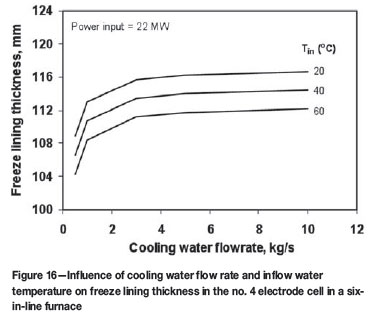
Compared with Figures 14 and 15, it can be seen from these results that the power input and complete air gap formation have much larger impacts on the freeze lining thickness than the cooling parameters (such as water flow rate and inflow water temperature). Nevertheless, this doesn't mean these cooling parameters are unimportant. In fact, it is crucial to maintain the water temperature low enough inside the cooling units, by applying a high enough water flow rate and as low as possible inflow water temperature, so as to avoid water boiling inside the cooling units which can lead to explosion accidents. For a given inflow water temperature, this situation can be effectively avoided by keeping water flow rate above certain threshold values, depending on furnace power input. Figure 17 gives the predicted threshold water flow rates below which the water with different initial temperatures (at 20ºC, 40ºC, and 60ºC respectively) could boil inside the cooling unit. In addition, the inflow water temperature affects the slope of the critical line shown in Figure 17. A lower inflow water temperature decreases this slope and thus reduces the 'boiling zone' in the figure.
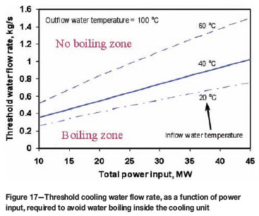
It should be mentioned here that the assumptions of steady-state heat transfer and, in particular, perfect contact between the freeze lining and the cooling unit, are not expected to always hold in industrial furnaces. Thus, the above results may not be reliably used directly for real processes. This is because, as mentioned earlier, air gap formation will also have a marked influence on heat transfer to the cooling unit and hence the threshold water flow rate.
Influences of slag bath and solid charge heights on specific power consumption in a six-in-line furnace
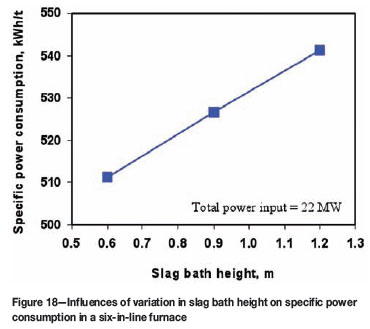
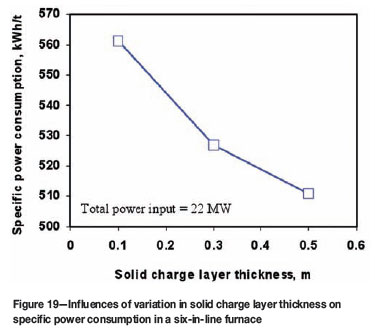
Figures 18 and 19 show, respectively, the influences of changing the heights of slag bath and solid charge layer on the specific power consumption, under the same total power input condition. We can see from these figures that an increase in slag bath height results in an increase of heat loss to cooling water and thus leads to increased specific power consumption. According to Figure 18, a decrease in slag bath height by 100 mm could save energy by about 5 kWh for smelting one ton of solid charge. Figure 19 indicates that a thicker solid charge would work as a thermal insulation layer in electric furnaces. This is rather advantageous for reducing the heat loss and therefore decreasing the specific power consumption. According to this figure, an increase of the solid charge layer thickness by 100 mm could decrease the energy consumption by 8 to 18 kWh for smelting one ton of solid charge, but this effect on energy saving tends to decrease for thicker solid charge layers. In general, the results shown in Figures 18 and 19 suggest that maintaining a shallower slag bath and a thicker solid charge layer above it would be favourable for minimizing the specific power consumption in electric furnace operations.
Optimization of electric power input in a six-in-line furnace
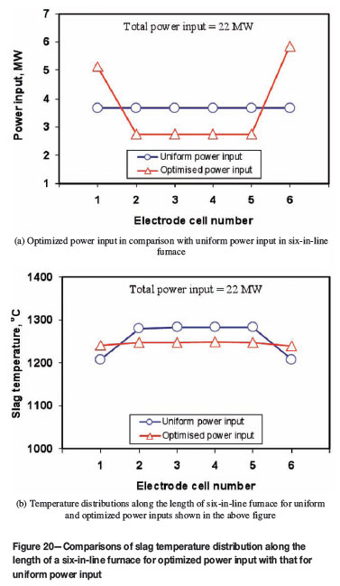
As shown in Figure 7, in six-in-line furnaces a uniform power input to the electrodes can lead to noticeably cold regions in the end electrode cells. This could be regarded as a major cause for the precipitation of chromite spinel particles in the slag bath in some South African electric furnaces smelting UG2 ores, as depicted in Figure 1. With the help of the present heat transfer model, it could be possible to minimize such spinel precipitation through optimizing the power input to the electrode cells in six-in-line furnaces, so as to realize more uniform heating in the furnaces. Figure 20 illustrates an example of using the model to find out an appropriate partition of the total electric power input to the six electrode cells to maintain a nearly even temperature distribution along the length of the furnace. In this work, modelling analysis was carried out on the effect of various controlling factors. As seen from Figure 20, adjusting the power input to the two end electrode cells (no. 1 and no. 6 cells) is quite effective. Nevertheless, the results shown in Figure 20 are just to elucidate one capability of the model in controlling power inputs to different electrode cells. The model doesn't suggest how to realize the optimum power input in practice and what side effects it would cause. One foreseeable effect would be that, if deeper electrode immersion depths were applied in the end electrode cells, more intensive bath agitation, due to more electrode gas stirring, could be expected in these cells. This would be beneficial, since it would stir up the precipitated spinel deposits but, on the negative side, it would increase the electrode consumption rate, decrease the freeze lining thickness, and result in too hot a freeboard releasing increased amounts of hot electrode gases, etc. In all, this is an area for further more detailed studies.
Conclusions
Based on the concept of heat transfer in multilayer composite material systems, an efficient and portable mathematical model for simulating heat transfer in six-in-line electric furnaces has been developed. The model has the following capabilities:
(1) Prediction of average temperatures in any material component (such as slag, matte, solid charge, freeze lining, and refractory lining etc.) and at any interface formed by two material components in the furnace
(2) Prediction of freezing lining thickness with or without air gap formation
(3) Prediction of smelting rate and heat loss rates
(4) Prediction of the lowest specific power consumption
(5) Optimization of power distribution in electrode cells
(6) Online implementation on industrial electric furnaces.
From the modelling results, the following conclusions can be drawn:
Acknowledgement
The authors would like to thank the CSIRO Minerals Down Under National Research Flagship for financial support for this work.
References
1. CRAMER, L.A. The extractive metallurgy of South Africa's platinum ores. Journal of Metals, 2001. pp. 14-18. [ Links ]
2. NELL, J. Melting of platinum group metals concentrates in South Africa. Proceedings of the VII International Conference on Molten Slags, Fluxes and Salts, Cape Town, South Africa, 25-28 January 2004. Johannesburg, The Southern African Institute of Mining and Metallurgy. pp. 165-170. [ Links ]
3. URQUHART, R.C., RENNIE, M.S., AND RABEY, C.C. The smelting of coppernickel concentrates in an electric furnace. Proceedings of Extractive Metallurgy of Copper: vol. 1. Pyrometallurgy and Electrolytic Refining. Yannopoulos, J.C. and Agarwal, J.C. (eds.). Warrendale, Pennsylvania, The Metallurgical Society of AIME, 1976. pp. 275-295.
4. SHENG, Y.Y. and IRONS, G.A. Mathematical and physical modelling of fluid flow and heat transfer in electric smelting. Canadian Metallurgical Quarterly, vol. 37. no. 3-4, 1998. pp. 265-273. [ Links ]
5. SHENG, Y.Y., IRONS, G.A., and TISDALE, D.G. Transport phenomena in electric smelting of nickel matte: Part 1. Electric potential distribution. Metallurgical and Materials Transactions B, vol. 29B, 1998. pp. 77-83. [ Links ]
6. SHENG, Y.Y., IRONS, G.A., and TISDALEI, D.G. Transport phenomena in electric smelting of nickel matte: Part 2 .Mathematical modelling. Metallurgical and Materials Transactions B, vol. 29B, 1998. pp. 85-94. [ Links ]
7. JARDY, A., ABLITZER, D., and JORGET, S. Modelling of slag behaviour in a non-ferrous smelting electric furnace. Proceedings of the Reinhardt Schumann International Symposium on Innovative Technology and Reactor Design in Extraction Metallurgy. TMS-AIME Fall Meeting for Extractive and Process Metallurgy, Colorado Springs, Colorado, 9-12 November 1986. Gaskell, D.R., Hager, J.P., Hoffmann, J.E., and Mackey, P.J. (eds.). pp. 419-431.
8. XIA, J.L. and AHOKAINEN, T. Numerical modelling of slag flows in an electric furnace. Scandinavian Journal of Metallurgy, vol. 33, no.4, 2004. pp. 220-228. [ Links ]
9. PAN, Y., SUN, S., and JAHANSHAHI, S. Efficient and portable mathematical models for simulating heat transfer in electric furnaces for sulphide smelting. Proceedings of the Sohn International Symposium on Sulphide Smelting, San Diego, California, 27-31 August 2006. Kongoli, F. and Reddy, R.G. (eds.). Warrendale, Pennsylvania, The Minerals, Metals and Materials Society. pp. 599-613. [ Links ]
10. GEIGER, G.H. and POIRIER, D.R. Transport Phenomena in Metallurgy. Addison-Wesley, Reading, Massachusetts, 1973. [ Links ]
11. ROHSENOW, W.M. and CHOI, H.Y. Heat, Mass and Momentum Transfer. Prentice-Hall, Englewood Cliffs, New Jersey, 1961. [ Links ]
12. WEAST, R.C., ASTLE, M.J., and BEYER, W.H. (eds.). CRC Handbook of Chemistry and Physics. 64th edn. CRC Press, Boca Raton, Florida, 1983-1984. [ Links ]
13. WHITAKER, S. Forced convection heat transfer correlations for flow in pipes, past flat plates, single cylinders, single spheres, and for flow in packed beds and tube bundles. AIChE Journal, vol. 18, no. 2, 1972. pp. 361-371 
Paper received Jun. 2010; revised paper received Jul. 2011.
© The Southern African Institute of Mining and Metallurgy, 2011. SA ISSN 0038-223X/3.00 + 0.00.
Appendix: nomenclature
Alphabetic symbols
| A | Heat transfer area (m2) |
| Asw | Heat transfer area between freeze lining and cooling unit (m2) |
| Cpc | Heat capacity of solid charge (J/kg·K) |
| Cpm | Heat capacity of liquid matte (J/kg·K) |
| Cps | Heat capacity of liquid slag (J/kg·K) |
| Cw | Heat capacity of water (J/kg·K) |
| Dw | Inner diameter of water pipe in cooling unit (m) |
| f | Heat transfer coefficient correction factor (dimensionless) |
| Fij | View factor between radiative surfaces i and j (dimensionless) |
| Gr | Grashof number (dimensionless) |
| Gm | Matte production rate in an electrode cell (kg/s) |
| Gs | Slag production rate in an electrode cell (kg/s) |
| Gsmelt | Solid charge melting rate in an electrode cell (kg/s) |
| Gw | Cooling water flow rate (kg/s) |
| h | Convection heat transfer coefficient (W/m2·K) |
| Hsmelt | Heat consumed for smelting per unit mass of solid charge (J/kg) |
| k | Thermal conductivity (W/m·K) |
| kss | Thermal conductivity of freeze lining (W/m·K) |
| L | Thickness of a material layer (m) |
| Lfreeze | Freeze lining thickness (m) |
| Lpipe | Total length of water pipe in cooling unit (m) |
| Nu | Nusselt number (dimensionless) |
| Pr | Prandtl number (dimensionless) |
| Qc | Heat flow rate for heating the solid charge (W) |
| Qc-cond | Net conduction heat flow rate in solid charge from the neighbouring electrode cells (W) |
| Qcf | Convection and radiation heat flow rate from the top surface of the solid charge to the freeboard space (W) |
| Qdroplets | Net sensible heat flow rate contributed by the descending slag and matte droplets produced at the slag/charge interface (W) |
| Qgas | Net heat flow rate absorbed by solid charge from the reaction gases generated by smelting at the slag/charge interface (W) |
| Q'gas | Net heat flow rate transported by the reaction gases evolving through the solid charge layer to the freeboard space (W) |
| Qg-conv | Net convection heat flow rate transported by bulk off-gas flow in the freeboard space from the neighbouring electrode cells (W) |
| Qingress-air | Rate of heat absorbed by ingress air in the freeboard space (W) |
| Qinput | Effective electric energy input rate (power) into slag bath in an electrode cell (W) |
| Qm | Heat flow rate for heating the newly produced matte droplets (W) |
| Qm-conv | Net convection heat flow rate transported by bulk matte flow from the neighbouring electrode cells (W) |
| Qm-droplets | Sensible heat flow rate contributed by matte droplets descending from the slag bath (W) Qs Heat flow rate for heating the newly produced slag droplets (W) |
| Qsc | Convection heat flow rate from slag bath to slag/charge interface (W) |
| Qscc | Conduction heat flow rate from slag/charge interface to the centre of the solid charge layer (W) |
| Qs-conv | Net convection heat flow rate transported by bulk slag flow from the neighbouring electrode cells (W) |
| Qsm | Convection heat flow rate from slag bath to matte bath (W) |
| Qsmelt | Net heat flow rate consumed for smelting the solid charge (W) |
| Qsw | Convection heat flow rate from slag bath to the surface of freeze lining layer (W) |
| R | Heat transfer resistance (K/W) |
| Rcw | Heat transfer resistance between copper and water in cooling unit (K/W) |
| Re | Reynolds number (dimensionless) |
| Rsc | Convection heat transfer resistance at the slag/charge interface (K/W) |
| Rscc | Conduction heat transfer resistance between the slag/charge interface and the centre of the solid charge layer (K/W) |
| T | Temperature (K) |
| Ta | Ambient (atmosphere or room) temperature (K) |
| Tb | Boundary temperature (K) |
| Tbulk | Temperature of bulk material (K) |
| Tc | Temperature at centre of the solid charge layer (K) |
| Tcw | Temperature at copper/water interface in cooling unit (K) |
| Tf | Temperature of bulk off-gas in the freeboard space (K) |
| Tm | Temperature of bulk matte (K) |
| Ts | Temperature of bulk slag (K) |
| Tsmelt | Temperature at the slag/charge interface, i.e. smelting zone (K) |
| Tsol | Solidus of freeze lining, i.e. solid slag, (K) |
| Tsurf | Temperature at material surface (K) |
| Tsurf,i | Temperature at material surface i (K) |
| Tsurf,j | Temperature at material surface j (K) |
| Tsw | Temperature of the cold face of the freeze lining layer (K) |
| Tw,in | Temperature of water flowing into cooling unit, (K) |
| Tw,out | Temperature of water flowing out of cooling unit, (K) |
Greek symbols
| ε | Surface emissivity (dimensionless) |
| σ | Stefan-Boltzmann constant (= 5.6703×10⁻⁸ W/m2·K4) |
| µ0 | Viscosity of fluid at interface (Pa·s) |
| µb | Viscosity of bulk fluid (Pa·s) |
Common subscripts
| i | Index number of material component |
| j | Index number of heat transfer direction |
| w | Subscript for water cooling parameters |

