


Servicios Personalizados
Articulo
 Inglés (pdf)
 Articulo en XML
 Referencias del artículo
Indicadores

Links relacionados
-
 Citado por Google
 -
 Similares en Google
Compartir

 Permalink
Journal of the Southern African Institute of Mining and Metallurgy
versión On-line ISSN 2411-9717
versión impresa ISSN 2225-6253
J. S. Afr. Inst. Min. Metall. vol.111 no.10 Johannesburg oct. 2011
TRANSACTION PAPER
The dual-electrode DC arc furnace-modelling insights
Q.G. Reynolds
Mintek, Randburg, South Africa
SYNOPSIS
The dual-electrode direct current (DC) arc furnace uses two graphite electrodes, one connected as cathode and one as anode. Such an arrangement avoids some of the design difficulties associated with the anode hearth traditionally used in single-electrode and twincathode DC furnaces, but can introduce other design and operational difficulties including deflection of the arcs toward the furnace walls. Counter-intuitively, both arc jets in a dual-electrode furnace travel from the electrode down to the bath surface, despite carrying electric current in opposite directions-this is suggested in the theory of the governing equations of arc formation, and confirmed by experiments using high-speed photography. The dualelectrode arc system at small pilot-plant scale is studied using a transient magnetohydrodynamic model capable of predicting arc deflection and interaction from first principles, and the results are compared to the behaviour of twin-cathode systems at similar power. Finally, a simple arrangement of the furnace busbars, M configuration, is shown to provide some passive protection against arc deflection.
Keywords: pyrometallurgy, furnace, DC, reverse polarity, dual-electrode.
Introduction
DC arc furnaces have been proposed or used for a wide variety of applications in pyrometallurgy to date, including scrap steel remelting, and smelting of a range of materials including chromite to produce ferrochromium1, ilmenite to produce titania slag and pig iron2, non-ferrous smelter slags to recover cobalt3, nickel laterites to produce ferronickel4, and ores containing platinum group metals5.
With the growing interest in DC furnaces, opportunities for retrofitting existing circular furnaces have begun to arise. A significant problem in such repurposing exercises is how to connect the anode and cathode of the DC power supply to the furnace vessel; in the case of a new furnace plant, this would typically be done by designing the DC furnace with one or possibly two graphite electrodes acting as cathode(s), and a hearth containing either conductive bricks, multiple pins connected to a 'spider plate', or billets, acting as the anode.
Such conductive hearth designs can be expensive to manufacture and license, and obviate some of the cost saving and convenience associated with reusing existing furnace vessels.
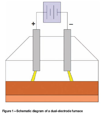
One possible solution to the problem is to use two electrodes entering through the roof of the furnace, one connected as anode and one as cathode. DC current (following the conventional elect rical engineering convention) then travels down the anode, through the molten bath, and up the cathode. Two arcs would be formed in the furnace, one between each electrode and the molten bath surface. This is shown schematically in Figure 1.
Such a configuration differs from the more familiar conductive-hearth DC arc furnace, and has a number of pros and cons when compared against it.
Advantages:
Simplified hearth design
Disadvantages:
The techno-economics of a dual-electrode DC arc furnace would need to be considered carefully on a case-by-case basis to determine whether or not this type of design is feasible. It should be noted that the present work assumes a direct comparison of dual-electrode furnaces with single or twin-cathode furnaces, operating at similar arc lengths and other parameters-it is highly likely that industrial dualelectrode furnaces would operate in different regimes. For example, reducing the arc length6,7 is one potential means of limiting the effect of several of the drawbacks listed above, such as high voltages and excessive arc deflection.
The current work addresses one of the important disadvantages, arc deflection behaviour, and suggests how it could be corrected.
Plasma arc model
The DC plasma arc system is a tightly coupled problem involving mathematical relationships governing the fluid dynamics, energy transfer, and electromagnetic fields8,9. The equations describing these various fields must be derived, and solved simultaneously, in order to model the overall behaviour of the system.
For the fluid dynamics component, incompressible flow with constant physical and transport properties is assumed:
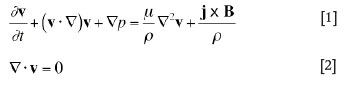
Here, v is the fluid velocity, ρ is the fluid density, p is the reduced pressure (P/ρ), µ is the kinematic viscosity, j is the electric current density vector, and B is the magnetic field vector.
The energy transfer relationship assumes that the thermal plasma making up the arc is in local thermodynamic equilibrium, permitting the use of a single temperature to characterize the material properties:
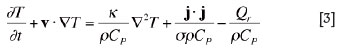
Here, T is the plasma temperature, CP is the heat capacity at constant pressure, κ is the thermal conductivity, σ is the plasma electrical conductivity, and Qr is the radiation energy loss per unit volume. Both σ and Qr are strong functions of temperature.
Magnetostatic and electrostatic laws complete the plasma arc model:
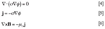
Here, φ is the electrostatic potential, and µ0 is the permeability of free space.
This set of equations describes (approximately) the fundamental physics that governs the behaviour of the arc system. An important aspect of this formulation is the retention of the time dependence of all transport equations, permitting the temporal evolution of the arc to be modelled.
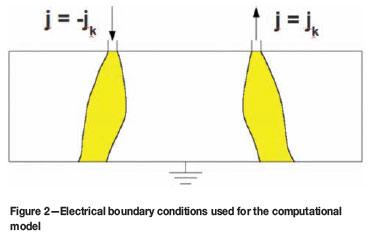
Electrical boundary conditions for the dual-electrode plasma arc model are shown in Figure 2. The model simulates a rectangular region of the furnace, between the tips of the electrodes and the bath surface. Current density is specified on each of two arc attachment zones for the anode and cathode arcs. Current density at the anode attachment zone is specified to be equal in magnitude (jk = 3.5 kA/cm2)8 and opposite in direction to that at the cathode. The roof and walls are assumed to be electrically insulating, and the bath surface is assumed to be at ground potential-this simulates a highly conductive material such as graphite, molten metal, or a low-resistivity slag. Additional boundary conditions for temperature, velocity, and other fields are described in detail in previous work9.
In order to perform calculations with the model, the equations are translated into numerical form9and written into computer code using the C language. The model runs were performed using various 32- and 64-bit Linux platforms at Mintek and the CSIR/Meraka Centre for High Performance Computing.
Polarity reversal and its effect on the arc
The plasma arc, as modelled, is a coupled multi-physics problem. The passage of current through the hot plasma gas maintains its temperature, and hence electrical conductivity, and additionally generates a self-magnetic field in and around the arc column. Interaction with the current field then provides the momentum source for the arc jet via the Lorentz j x B force term in Equation [1]. This acts predominantly in the region surrounding the arc attachment spot on the surface of the graphite electrode-as the current constricts to travel through the spot, the pinching of the electric and magnetic fields results in a force on the plasma gas directed toward the centre of the spot and away from the surface of the electrode. This is the Maecker acceleration force8, and results in the formation of a strong jet directed away from the electrode surface.
The effect of reversing the direction of current flow through a DC plasma arc is at first somewhat counter-intuitive-it does not change the direction of plasma gas flow in the arc at all, only the direction of motion of the electrons carrying the current.
This fact is suggested by the structure of the governing equations of the system. Consider reversing the direction of the current by setting j =-j in Equations [4], [5], and [6]. The reversed current results in the electric field being inverted (φ = -φ). The relationship between current and magnetic field is a linear differential equation with homogeneous boundary conditions, so we also have B =-B. The vector products in the source terms in Equations [1] and [3] become

and

respectively, implying that the ohmic heating and, most importantly the vector forces acting on the plasma fluid, remain exactly the same as if the polarity had remained unchanged. One would therefore expect a reverse polarity arc to behave much like a traditional polarity arc.
Some second-order differences related to the asymmetry of the electron emission surfaces are likely, particularly where energy transfer to the anode and cathode are concerned-the electron flow is capable of carrying a significant fraction of the energy load due to work function considerations10, and this is delivered at the surface on which electrons are absorbed. In the case of the cathodeelectrode arc, this surface is the molten bath, and for the anode-electrode arc, it is the electrode.
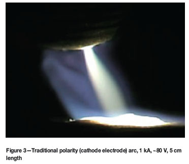
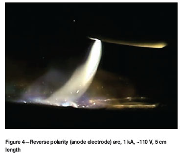
The somewhat surprising idea that reversing polarity may not substantially affect the arc behaviour is supported by evidence from high-speed photographic studies of arcs running in air on graphite blocks, using both reverse and traditional polarity electrical connections. Some still frames from recordings at 5 000 frames per second and 2 µs shutter speed are shown in Figures 3 and 4 below, which clearly show that the direction of the arc jet is from electrode down to bath/block surface in both cases.
Results and discussion
The three-dimensional reverse-polarity arc model was used to study a number of different cases. Of particular interest in such models is the degree of arc deflection predicted, and the effect that various parameters have on it.
Comparison of twin- and dual-electrode systems
Behaviour of twin-cathode arcs has been studied in earlier work9. It is of some interest to compare results from the dualelectrode model to those from the twin-electrode model at similar parameters, shown in Table I.
In Table I, dE is the diameter of the electrode surfaces, TWALL, TSURFACE(BATH) and TSURFACE(ELECTRODE) are the boundary temperatures of the walls, the bath surface, and the electrode surfaces respectively, and IE is the current carried by each arc in the model (I1 = I2 = IE for twin, I1 = -I2 = IE for dual). The plasma gas used is air.
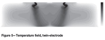
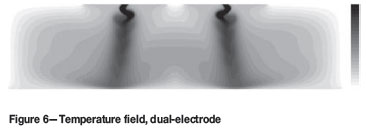
In Figures 5 and 6, a comparison of the temperature profiles (x-z projection of the three-dimensional temperature field) at 10 ms shows clearly the effect of reversing the polarity; the arcs in the dual case now repel each other, which results in the arc jets pointing toward the sidewalls of the furnace rather than toward the centre. The temperature scale is 2 000 K (white) to 10 000 K (black).
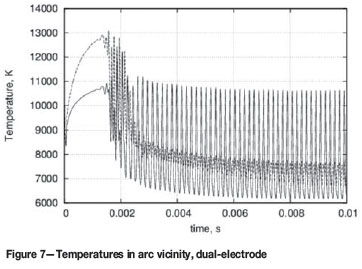
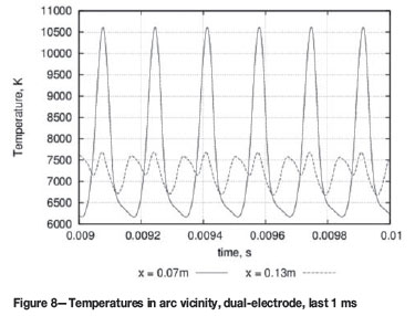
The transient behaviour of low-current arcs in the dual-electrode case is very similar to that seen in the twinelectrode system9. Although initially forming steady arc columns, both anode and cathode arc soon break down into regular oscillatory motion, resulting in helical structures within the arcs.
This behaviour can be seen in Figures 7 and 8, which show the changing temperature in the vicinity of each arc's attachment spot over time ('x = 0.07 m' refers to the arc at the anode electrode, and 'x = 0.13 m' refers to that at the cathode).
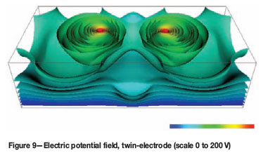
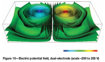
The change in polarity between dual and twin configurations results in significant differences in the distribution of electric potential in the space around the electrodes. This can be seen in Figures 9 and 10, where the voltages at each individual arc range between 200 V and 205 V. In the dualelectrode case there is marked asymmetry between the potentials at each electrode, with the anode electrode running at a negative voltage with respect to ground, and the cathode running at a positive voltage. In the twin case, the cathode electrodes both run at similar voltages above ground potential. This has a profound effect on the electrical requirements of the furnace and the resulting DC power supply-at a fixed furnace power and arc lengths, a twin-electrode system will run at approximately one half the voltage and double the current when compared to a dualelectrode furnace. This is due to the fact that, in the twin case, the arcs run in parallel, with total furnace current being split between them, and in the dual case, in series, with total furnace current passing through each arc in turn.
Effect of changing electrode separation
Due to the repulsive force that acts between the arcs in the dual-electrode furnace, arc deflection may have a negative effect on the containment vessel in such furnaces. If the deflection is significant, it is possible that the arc tail flames will result in 'hot spots' or high energy transfer zones forming on the vessel wall areas closest to each arc. This is a familiar problem from AC three-electrode circular furnaces, which also feature arcs carrying current in opposite directions, albeit in a transient manner.
An understanding of the severity of the deflection in the dual-electrode arc system, and how it is affected by various design parameters, is therefore of some importance. The parameters used in the arc separation models are identical to those in Table I, with the exception of the 'arc separation' number, which is varied between 2 cm and 9 cm. These somewhat arbitrary separation distances were chosen to facilitate direct comparison with previous work on twinelectrode systems9.
In order to remove some of the short-term transient behaviour from the results, the temperature field data is time-averaged over the final 2 ms of model time. Projections in the x-z plane are computed to reduce the dimensionality of the data from three to two, and are presented in Figures 11 to 14. The temperature scale is 2 000 K (white) to 10 000 K (black).
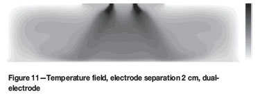
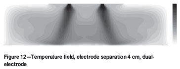
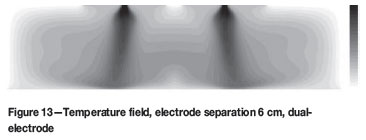
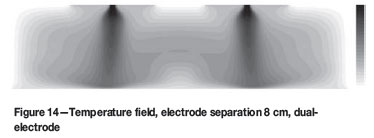
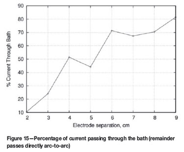
It can be seen that, as the arcs are brought closer together, the degree of deflection away from the centre line increases significantly, as repulsive forces between the arcs scale with the inverse of the separation distance between the arc columns. It is interesting to observe the formation of a 'hot zone' at the centre of the furnace (between the arcs) for very small electrode separations, suggesting that a significant fraction of the current flow is able to bypass the bath surface and short-circuit between electrodes under these conditions. A calculation of the current fraction passing through the bath as a function of the arc separation is shown in Figure 15, and supports this hypothesis.
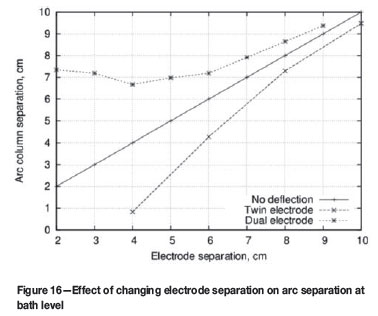
The arc separation at bath level may be calculated from these results, as an indicator of the degree of deflection. This is shown as a function of the specified electrode separation for both twin9and dual-electrode systems, in Figure 16. For the dual system, a minimum in arc separation occurs at an electrode separation comparable to the length of the arcs.
Mitigation of arc deflection using M-configuration
A number of different methods may be used to control the arc deflection toward the sidewalls in various types of electric furnaces. Busbar design11, separate externally-powered magnetic fields, and indirect methods, such as sidewall feeding and bank formation, can all help to reduce the thermal impact of the arc tail-flames on the cooling and containment systems.
One simple method applicable to the dual-electrode furnace is to make use of passive control-by taking advantage of symmetries in the system, careful positioning of the busbars carrying the current to the electrodes can provide a superimposed magnetic field that pushes the arcs closer together, thereby reducing or even reversing the deflection.
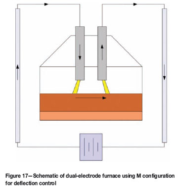
In order to achieve this, the busbars must be placed outside the furnace shell in the same plane as the electrodes. These compensating busbars should run vertically and be long enough to appear to the dual-electrode arc system as infinite conductors. Current to the furnace is then carried from the power supply, up one compensating busbar, down the anode electrode and arc, through the molten bath, up the cathode arc and electrode, down the second compensating busbar, and back to the power supply. It is assumed that all other busbars form a magnetically balanced system, so that only the effects of the compensating busbars are felt inside the furnace. This arrangement is called 'M' configuration, after the shape of the current path, and is shown schematically in Figure 17 (arrows indicate direction of current flow).
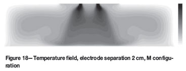
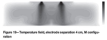
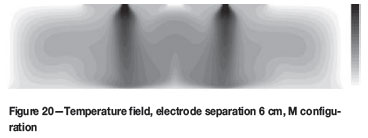
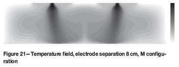
In order to study the effects of M configuration, the arc separation cases in the previous section were re-run with the addition of a static magnetic field generated by two vertical busbars positioned 9 cm away from each electrode (2 cm outside the calculation region on either side). These busbars were assumed to be carrying the furnace current of 250 A in opposite directions, as per Figure 17.
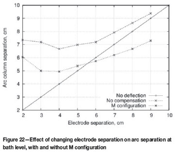
Figures 18 to 21 show selected time-averaged temperature fields for the final 2 ms of arc motion, projected in the x-z plane. The temperature scale is 2 000 K (white) to 10 000 K (black). The use of M configuration is of limited effectiveness at small electrode separations, where repulsion between the arcs overcomes the compensating field. However, as the distance between the electrodes grows, the arc deflection is increasingly influenced by the external busbars. At between 4 cm and 6 cm separation, the deflection is entirely neutralized, and beyond this point the arcs are deflected back inward toward the centre of the furnace.
The quantitative deflection behaviour with and without M configuration is shown in Figure 22. For this small system, the optimal electrode separation is between 5 cm and 6 cm.
Using the same approach, it is also possible to perform the inverse design calculation, that is, to find the optimal placement of the M configuration compensating busbars for a given electrode separation. This situation may arise if the positions of the electrodes are imposed by an existing furnace or feed system design.
Conclusions
A new type of multiple-electrode DC arc furnace has been analysed at small scale using mathematical and numerical modelling. The dual-electrode furnace uses one cathode and one anode electrode in order to avoid the difficulties involved in hearth anode design, especially in cases involving retrofitting of existing furnace vessels to DC operation.
Although reversing the polarity of DC arcs was shown to have little or no effect in terms of the directionality and structure of the arc jet, it is important to note that dual-electrode furnaces will run at higher voltages and lower currents than many typical hearth-anode-based DC furnace designs, assuming the same arc lengths and furnace power are used. This is due to the electrical topology of the dualelectrode system that connects two arcs in a series circuit, and may limit the applicability of such furnaces to the treatment of low-resistivity bath materials such as scrap steel, ferrochromium, and titania slag. Reducing the total voltage is also possible if the furnace is operated with shorter arcs6,7.
A significant issue in the dual-electrode design is arc deflection, and the resulting tail-flame flare and excessive energy transfer toward the furnace walls. This effect was studied using the numerical models at low currents typical of small pilot-plant-scale operations, with large deflection being observed at smaller electrode separation values of the order of the arc length. A means of compensating for the arc deflection is suggested in the form of M configuration, an arrangement of external busbars designed to passively limit the repulsion of the arcs in a dual-electrode furnace. An example case of M configuration was tested with the numerical models, and was shown to reduce and even reverse the direction of the arc deflection and resulting tailflame heating.
Open questions for further study include the effect of furnace current on the dual-electrode system and deflection compensation, particularly as the arc behaviour makes the transition to the more chaotic, irregular motion typically seen at large pilot-plant and industrial scales.
Acknowledgements
This paper is published by permission of Mintek. The author would like to thank Lourens Erasmus and GLPS for permission to publish Figures 3 and 4, the University of Cape Town for assistance with the DC plasma arc model development, and the CSIR/Meraka Centre for High Performance Computing for providing access to SMP platforms to run the numerical models.
References
1. SAGER, D., GRANT, D., STADLER, R., and SCHREITER, T. Low cost ferroalloy extraction in DC-arc furnace at Middleburg Ferrochrome. Proceedings of the Twelfth International Ferroalloys Congress, 2010. Helsinki, Finland, Outotec Oyj. pp. 803-814. http://www.pyrometallurgy.co.za/InfaconXII/803-Sager.pdf [ Links ]
2. GOUS, M. An overview of the Namakwa Sands ilmenite smelting operations. Proceedings of the Southern African Pyrometallurgy 2006 Conference, 2006. Southern African Institute of Mining and Metallurgy, pp. 189-201. http://www.pyrometallurgy.co.za/Pyr02006Papers/189_Namakwa.pdf [ Links ]
3. JONES, R.T., DENTON, G.M. REYNOLDS, Q.G., PARKER, J.A.L., and VAN TONDER, G.J.J. Recovery of cobalt from slag in a DC arc furnace at Chambishi, Zambia. Journal of the Southern African Institute of Mining and Metallurgy, vol. 102, no. 1, January/February 2002. pp. 5-9. http://www.mintek.co.za/Pyromet/Files/Chambishi.pdf [ Links ]
4. KOTZE, I.J. Pilot plant production of ferronickel from nickel oxide ores and dusts in a DC arc furnace. Minerals Engineering, vol.15, no. 11S1, 2002, pp. 1017-1022. http://www.mintek.co.za/Pyromet/Files/Ferronickel2002.pdf [ Links ]
5. Jones, R.T. Towards commercialisation of Mintek's ConRoast process for platinum smelting, Nickel and Cobalt 2009: Advances in the Processing of Nickel, Cobalt and PGMs using Pyrometallurgical Techniques, 48th Annual Conference of Metallurgists, Sudbury, Ontario, Canada, 23-26 August 2009. pp. 159-168. http://www.mintek.co.za/Pyromet/Files/2009-ConRoast-CIM.pdf [ Links ]
6. GREYLING, F.P. and GREYLING, H.W. Submerged Arc DC Furnace. South African Patent 2009/03078, 2010. [ Links ]
7. GREYLING, F.P. and GREYLING, H.W. DC Brush Arc Furnace for Ferrochrome Production. South African Patent Application 2010/06472, 2010. [ Links ]
8. BOWMAN, B. Properties of arcs in DC furnaces. Proceedings of the 52nd Electric Furnace Conference. Warrendale, Iron and Steel Society, 1995, pp. 111-120. [ Links ]
9. REYNOLDS, Q.G., JONES, R.T., and REDDY, B.D. Mathematical and computational modelling of the dynamic behaviour of direct current plasma arcs, (Infacon 12, Helsinki, 6-9 June 2010). Journal of the Southern African Institute of Mining and Metallurgy, vol. 110, no. 12, December 2010. pp. 733-742. http://www.saimm.co.za/Journal/v110n12p733.pdf [ Links ]
10. USHIO, M., SZEKELY, J., and CHANG, C.W. Mathematical modelling of flow field and heat transfer in high-current arc discharge. Ironmaking and Steelmaking, no. 6, 1981. pp. 279-286. [ Links ]
11. EVERS, H. Arc deflection in DC smelters: calculation, commissioning and design of furnaces with minimised arc deflection. Proceedings of Heavy Minerals 1999, Southern African Institute of Mining and Metallurgy, 1999. pp. 193-200. [ Links ] 
This paper was first presented at the Southern African Pyrometallurgy Conference, 6-9 March 2011, Misty Hills, Muldersdrift.
© The Southern African Institute of Mining and Metallurgy, 2011. SA ISSN 0038-223X/3.00 + 0.00.

