


Servicios Personalizados
Articulo
 Inglés (pdf)
 Articulo en XML
 Referencias del artículo
Indicadores

Links relacionados
-
 Citado por Google
 -
 Similares en Google
Compartir

 Permalink
Journal of the Southern African Institute of Mining and Metallurgy
versión On-line ISSN 2411-9717
versión impresa ISSN 2225-6253
J. S. Afr. Inst. Min. Metall. vol.111 no.10 Johannesburg oct. 2011
TRANSACTION PAPER
Cracking a hard nut: an overview of Lonmin's operations directed at smelting of UG2-rich concentrate blends
J.J. Eksteen; B. Van Beek; G.A. Bezuidenhout
Lonmin Platinum, Marikana, South Africa
SYNOPSIS
Lonmin, earlier than any other primary platinum producer, had to deal with the concentrating and smelting of UG2-rich ores and concentrates respectively. Smelting was performed at a fairly modest scale compared to the company's industry peers in the platinum group metals (PGMs) industry, and was focused on smelting concentrates obtained through low mass pulls while still maintaining high recoveries at its concentrators. Lonmin gradually smelted larger quantities of UG2 concentrates. Initially two 2.3 MW Infurnco furnaces were commissioned in 1982, followed by three 5 MW circular 3-electrode Pyromet furnaces in 1991. Deep electrode immersions and moderately high hearth power densities were used in all the designs. Lonmin decided to continue with circular furnace technology when it planned its new high-intensity No. 1 Furnace. Neither Lonmin nor the technology supplier and EPCM company foresaw the challenges that scale-up would bring when applied to the smelting of UG2-rich concentrate blends. Superimposed on the high chromite content, was the low base-metal loading, mineralogical difficulties, and fine particle size that resulted from milling of all concentrates (especially UG2 and recycle materials within the smelter). Through a process of fundamental diagnoses of furnace run-outs and wear patterns observed during repairs, the main challenges operating this high-intensity furnace were identified as sulphur vapour corrosion of the copper coolers, uneven and unpredicted movements of refractory bricks with associated copper cooler lift and matte tapblock movement, the formation of three-phase 'mushy' zones, high refractory and taphole wear rates, uncertainty in matte level and associated insufficient matte buffer height, and high furnace operating temperatures. These factors seldom worked in isolation and will be explored in more detail in the paper. The variability in furnace feed characteristics led Lonmin to redesign Furnace No. 1, to invest in backup furnace capacity, and to invest in improved monitoring and control. These improvements consisted of online and high-frequency off-line monitoring of feed chemistry and mineralogy, online pressure monitoring of watercooled circuits, an alternative matte liquid level measurement in the furnace, and electrode immersion estimation. Improvements were also made at the converters by installing and utilizing optical spectral analysis of the converter flame to characterize converter behaviour and achieve the desired iron end-point for white matte. This paper also briefly discusses the current and future expansion plans, as well as ancillary operations at the smelter such as flue-gas handling and materials handling.
Keywords: pyrometallurgy, furnace, Lonmin, platinum, PGM, UG2
Company background
Lonmin is the world's third-largest primary platinum producer, and is one of a few fully integrated mine-to-market producers of platinum group metals (PGMs) in South Africa. The bulk of its operations are concentrated within the companies of Western Platinum Ltd and Eastern Platinum Ltd, both located close to Marikana in the North West Province of South Africa. Lonmin also has a mine and concentrator close to Lebowakgomo (the Messina group of mines which includes Baobab, Dwaalkop, and Doornvlei), as well as the prospecting rights to Akanani (previously AfriOre), where the PGM resource is hosted in the Platreef(instead of the traditional Merensky and UG2 reefs).
Lonmin has tended to operate smaller concentrators in close proximity to the mine shafts, to maintain a more stable input into the concentrators and allow optimization for high recoveries at low mass pulls, rather than larger centralized concentrators. Concentrating is performed using the mill-float-mill-float (MF2) approach. A significant portion of the PGMs in UG2 ore is locked in silicates, and requires fine to ultra-fine grinding to liberate them. Fine grinding has also recently been used for Merensky ores. During the past three decades (1980-2010), a few major have been evident in the field of PGM concentrate production and mining:
The proportion of UG2 concentrates has increased relative to Merensky concentrates. These concentrates are characterized by high Cr2O3 content, low basemetal content, and a high proportion of altered silicates such as talc
Up to the present, Lonmin's practice has therefore been to have small-to-medium concentrators at the shafts to produce high PGM grade (200-300 g/t) concentrates at high recoveries and small mass pulls (0.9-1.2%) using opencircuit mill-float-mill-float concentrator technology. The smelter is set up to be cost efficient on a per-PGM-basketounce basis rather than on a per-ton-of-concentrate-smelted basis. As UG2 has a low base-metal concentration, this leads to low matte falls of PGM-concentrated furnace matte, which in turn lowers the total tons of fayalitic slag formed during converting and the commensurate amount of SO2 being formed. The smaller amounts of furnace matte, converter slag, and off-gas do not warrant investment in continuous converting (Ausmelt/Isasmelt), slag cleaning furnaces, or acid plants respectively. In other words, by-product credits from UG2 in the form of refined Cu, Ni, Co, and sulphuric acid, with the exception of chromite from concentrator tailings, are not significant enough to make their recovery economic. The high-grade concentrates lead to high-grade converter mattes (0.5%-0.8% PGM in matte) being dispatched to the Lonmin base metals removal plant (BMR).
Lonmin's smelter and BMR are both located in Marikana. In contrast to other Ni-Cu base metal operations, which operate with base metals refineries (emphasis on refining Ni, Cu, and Co), the emphasis at Lonmin is on the rapid removal of Ni, Cu, Co, Fe, and S to produce a high PGM grade (65-75%) concentrate at high recovery, within a short pipeline time and low metal-in-process inventories. Mediumgrade Cu cathode and crude NiSO4 are therefore produced. Lonmin's BMR has been discussed by Steenekamp and Dunn1.
UG2 concentrates have a significantly larger proportion of Rh, Ru, Ir, and Os, compared to Merensky concentrates. These particular PGMs tend to behave differently from the other PGMs during converting (Ru, Os) and pressure leaching in the BMR (Rh, Ru, and Ir). In the converter, Ru and Os are more readily oxidizable compared to the other PGMs, and are partially lost as metal tetroxide species which have high vapour pressures. Dorfling et al.2have shown that Ru, Ir, and Rh are partially dissolved in the BMR autoclaves due to their relative solubility (compared to Pt, Pd, and Au) in oxygenated sulphuric acid at elevated pressure and temperature.
The PGM concentrates derived as residues from the BMR are sent to the precious metals refinery (PMR) located in Brakpan, south-east of Johannesburg.
This paper provides an overview of the smelter, and how technological development in the past three decades has improved Lonmin's ability to deal with higher volumes of high-UG2 concentrate blends.
High-level process description
Since its commencement in 1971 with the commissioning of a 12.5 MW Merensky six-in-line furnace, the Lonmin smelter has undergone considerable expansion, firstly with the commissioning of two 2.3 MW Infurnco circular furnaces in 1982 to smelt the UG2 concentrate. It further expanded by the commissioning of three 5 MW Pyromet circular furnaces in 1991. The latest development at the smelter was the introduction of the 28 MW furnace referred to as 'Furnace No. 1' for smelting both the UG2 and Merensky types of concentrates. This furnace was commissioned in February 2002.
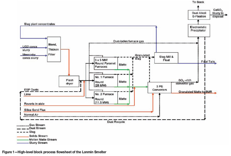
The process description given below provides a brief overview of the smelting complex. Some equipment, such as the spray-drying towers and Merensky furnace, has been placed on care-and-maintenance and is not indicated. The Merensky furnace will shortly be replaced by a new circular 3-electrode furnace (Furnace No. 2) more suited for high UG2 blend feeds, and will serve as a backup (in conjunction with the three small circular Pyromet furnaces if required). As there are many design similarities between the Pyromet furnaces, Furnace No. 1, and Furnace No. 2, and all are fed with the same feed blend, only Furnace No. 1 will be discussed in detail.
A high-level process flowsheet block diagram is presented in Figure 1.
Blending and receiving section
In the past, Lonmin managed two separate blends at the smelter-a lower Cr2O3 feed material through the spray dryers to the six-in-line Merensky furnace, and a higher Cr2O3 feed material through the flash dryer to the circular furnaces. In early 2009, a decision was taken to operate only a single blend and the six-in-line Merensky furnace and spray dryers were therefore placed on care-and-maintenance. The low proportion of Merensky in the concentrate mix did not allow running the six-in-line furnace in addition to Furnace No. 1 and the Pyromet furnaces. This decision facilitated a simplification of the blending section, and allowed better control of the overall feed to the furnaces.
There are three offloading bays at the smelter where slurry from the seven Lonmin concentrators can be received. All tankers are pumped to four blending tanks, according to level and availability. From the four receiving tanks, all concentrate slurry is pumped to a large filter feed tank. The size of the filter feed tank assists with homogenization by buffering the large difference in concentrate composition being received from individual tankers.
Internal smelter recycle material is prepared in the slag plant section. Recycle material is dispatched to the blending section and can also serve as a buffer by acting as a source of high Cu+Ni material with low Cr2O3.
As some concentrators produce filter cake concentrate, this can also be used to assist with the blend. Filter cake is stored in a large shed and can be added to the blend by adding it either as feed to the flash dryer or to the mill repulping circuit at the slag plant.
Blending is managed daily, by scheduling tanker deliveries and internal slag plant dispatches. Deliveries are scheduled from the concentrators according to availability and historical 3-day moving-average compositions. Currently, blending is managed with two factors only: Cr2O3 and Cu+Ni. Both of these measures have a maximum specification, while Cu+Ni also has a minimum specification to which the blend must be controlled.
Metal accounting on all received filter cake concentrate is assisted by an auger sampler located at the offloading shed. The smelter weighbridge is used to measure the mass of all filter cake and slurry received. Slurry concentrate is sampled at the concentrator during dispatch.
Due to lengthy turnaround times of concentrate assays, the smelter recently installed a Blue Cube® optical reflectance spectroscopy sensor at the offloading section. This unit provides immediate analyses during offloading and serves as an early warning system where concentrator composition has changed (for instance a change in ore type). A Blue Cube® sensor was also installed on the slag plant dispatch line to monitor internal recycle dispatches. The importance of blending and controlling a stable feed blend to the furnace will be discussed in a later section, where the impact of high-UG2 blends on furnace and converter operation are discussed in more detail. An investment was also made in a rapid (shift-based versus daily composite) turnaround laboratory to perform X-ray fluorescence (XRF) analyses on total elemental analyses, and X-ray diffraction (XRD) modal analyses on concentrates and smelter intermediate materials.
Filtering and drying section
The filtering plant consists of a newly installed Larox press filter, a Seprotech press filter, and two Hoesch press filters (which will be placed on care and maintenance after Larox commissioning in February 2011). The total capacity of the Larox filter, together with the Seprotech filter, matches the flash dryer capacity at 40 tons per hour of dry product.
The filters produce filter cake with between 16% and 17% moisture. The reason for this moisture content is due to the relative density (sometimes referred to as 'specific gravity' or SG) of the slurry to the filter feed running at between 1.55 and 1.65, and to the very small particle size of the Lonmin concentrate. The SG of the filter feed material is measured, and in times when the SG drops below 1.55 a Magra high-rate thickener can be brought on line.
The drying section consists of one Drytech fluid-bed flash dryer and two spray towers. As already mentioned, the spray towers have been placed on care- and- maintenance. During operation of the spray towers, excessive nozzle wear was experienced, aggravated by erosion by abrasive chromite in UG2 concentrates and internal recycled material.
The flash dryer is the drying technology of choice due to the high energy utilization efficiency and high availability. However, it has the disadvantage that particle agglomeration cannot be facilitated during drying. Particle size distribution and its effect in the furnace is discussed in a later section. Lonmin is currently investigating the feasibility of particle micro-agglomeration.
Multivariable control was implemented on the flash dryer by CSense in 2007 by tying together control loops over the flash dryer. This stabilized the control over the flash dryer and had a significant impact on efficiency and availability, as reported by Chaitram and Rademan3.
In an effort to buffer the affect of variations in mine and concentrator production on the furnace operation, Lonmin invested in silo storage space, with an installed silo storage capacity of around 11 500 tons (translating to around 20 days of furnace feed inventory). Filter cake can also be stored in a large shed.
Slag plant section
Additional recovery and recycling of material at the smelter is done at the slag plant section. Furnace and converter slags are separately granulated into granulation ponds, dewatered, and transferred to the slag processing plant. This section consists of a crushing circuit (primary jaw crusher and secondary cone crusher), two ball mills, and a flotation circuit. Materials are crushed, sampled, and stored according to the origin and PGM content.
All slag at the smelter (furnace and converter slag) is blended to control head-grade feed, milled in one of the mills, and sent through a flotation circuit at a mass pull of around 3.5-4.5%. The recovery of PGMs from slag to slag concentrate is around 85%. The tails from the flotation circuit is pumped to one of the nearby concentrator tailings dams.
A second mill is used to repulp reverts, which is typically high-grade aisle reverts and ungranulated converter slag. Slag concentrate from the flotation circuit and repulped reverts are thickened together and dispatched to the blending section according the blending plan.
Refractory bricks originating in the smelter are manually sorted in order to separate 'clean' bricks from impregnated bricks. 'Clean' bricks are sold to a refractory supplier, while the impregnated bricks are crushed, milled, and floated.
Smelting section
The Lonmin smelter comprises five furnaces, namely a 3-electrode circular 'Furnace No. 1', a six-in line Merensky furnace (soon to be replaced by a 3-electrode circular furnace, namely 'Furnace No. 2') and three small circular 3-electrode furnaces, called 'Pyromets', based on the company who built the furnaces at the time.
The furnace inner dimensions, the rated hearth power densities, and the maximum power ratings, are:
The Merensky furnace did not have sufficient hearth power density at typical feed rates, nor could it operate at sufficiently deep electrode immersions at appropriate power to deal with UG2 rich blends. Improving this would have required a hearth and tapblock redesign, and the installation of cooled sidewalls. As the upgrade would have required significant changes, it was decided to design the optimal furnace (Furnace No. 2) that could be a backup for Furnace No. 1 (ability to handle variable material feed, startups, turndown ratios, etc.).
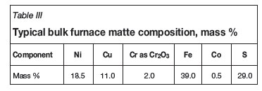
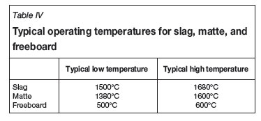
Tables I, II, and III summarize Lonmin's operating data for typical furnace feed, furnace slag, and furnace matte respectively, while Table IV indicates the typical operating temperatures.


Furnace No. 1 can typically smelt 16 500 tons of concentrate per month at 20 MW.
Matte entrainment in slag typically ranges between 0.10% and 0.16%, depending on electrode immersion, feed grade, and hearth power density.
The only fluxing agent added to the furnace is lime, in the form of finely powdered burnt lime. Lime addition is normally controlled between 5% and 10% of the concentrate mass feed.
Converter section
Lonmin operates three identical Peirce-Smith converters, with each unit sized as 10 ft x15 ft (3.048 m x4.572 m). There are 16 tuyeres per converter, with the tuyere diameter being 50 mm. The plant has three blowers, sized to deliver an average converter airflow of 13 000 Nm3/h each. Converters and blowers are operated on a 2-in-service and 1-on-standby basis.
Both silica (as fluxing agent) and cold dope (or revert) additions are made through a top vibratory feeder system. Ladles in the Lonmin aisle are sized to carry approximately 8 tons of furnace matte to the converters, and 8 tons of converter slag or converter matte to their respective granulation stations. There are separate furnace matte ladles (with a cast lining) and converter ladles (transporting converter slag and converter matte with a slag freeze-line).
Movements in the aisle can be regarded as the normal smelter bottleneck. The reason for this is principally the small converter size, coupled with small ladle size. At the time the decision was taken on the converter equipment sizing, the Lonmin mining plan was very much aimed at high UG2 ore ratios. As UG2 nominally contains low quantities of base metal sulphides, furnace matte fall and movement in the aisle were not foreseen as presenting capacity issues at the time.
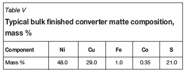
The typical composition of finished converter matte produced in the Lonmin converters is shown in Table V. Operating temperatures in the converter are controlled via a top-mounted pyrometer, and temperatures are normally controlled below 1270ºC.
There are no water-cooling panels used on the converter hoods, as Lonmin does not operate an acid plant that requires a minimum SO2 concentration. Dilution air is sucked in through the hood/converter gap at a nominal ratio of around 3:1 (dilution air versus air flow through converter tuyeres).
A number of changes have been made, or are in the process of being made, to improve both process control and fugitive gas handling at the converters. In the case of process control, the use of flame optical emission spectroscopy has been introduced, to better quantify and monitor the progression to the end-point of the blow. For Lonmin's BMR, there are numerous reasons why an end-point of around 1% Fe (0.6% to 1.6%) is preferred. In addition, it has numerous benefits in controling Co Ni, and Cu losses, and excessive S loss (which must be made up in the BMR with additional sulphuric acid). A detailed description of Lonmin converter matte mineralogy, and the dependence on iron end-point, was provided by Thyse et al.4. The effect of converter endpoint on BMR first-stage leach behaviour was discussed by Van Schalkwyk et al.5.
There are many benefits to having this iron end-point (~1%) while still remaining within the processing constraints of the BMR. However, as this preferred end-point is more difficult to detect reliably with the naked eye than lower iron end-points (which are clearly visible due to the green tinge of the flame), optical spectroscopic monitoring of the converter flame becomes essential. A description of the flame optical emission spectroscopy using the so-called Semtech technology is described by Persson et al.6,7. The implementation of the Semtech technology at Lonmin has been described by Bezuidenhout et al.8. Other than end-point, the Semtech technology leads to a generally improved knowledge of the state of the slag and the bath and the dynamics of the converting process. Process monitoring using the Semtech sensor is reliable as long as good converting practices are followed. For example, plugging, and localized over-oxidation of the bath might lead to showing a false conversion to endpoint prior to reaching the actual desired end-point, leading to too high an iron concentration in the matte. However, this error also occurred when human operator control based on visual inspection of flame colour was used, as local overoxidation also leads to the flame being tinged green before the bulk of the matte has reached the required end-point. Other caveats in the use of the Semtech technology are that good slag coverage of matte is required, and that proper slag skimming procedures have to be implemented and followed during converting. Despite automation, good and disciplined operator practice is still required.
Off-gas handling section
The gas-cleaning circuit at the Lonmin smelter consists of a two-field dry electrostatic precipitator (ESP), variable-throat scrubber, and a concentrated mode Dual Alkali plant. The offgases from the furnaces are combined and pass through the ESP, while the converter off-gases bypass the ESP and combine with the furnace gas at the feed to the variablethroat scrubber. Efficiencies of the ESP on particulate removal are very high (> 98%), while the variable-throat scrubber was sized to handle a full particulate loading in event of the off-gas completely bypassing the ESP.
In 2002, Lonmin made a decision to install a concentrated mode Dual Alkali scrubber. The decision at that point was driven by two main factors:
1. The SO2 concentration in Lonmin off-gas typically varies between 0.5% and 6% (depending on furnace and converter operation). The high end of the gas SO2 concentration was seen to be too high to be handled by pure lime-based scrubbing, while the low end of the gas SO2 concentration was unfit for an acid plant operation. There were references of concentrated mode Dual Alkali operation on high SO2 gas concentrations, while other technologies were only just emerging at the time
2. Lonmin specialized in UG2 smelting with low sulphide content. The sulphur emissions required effective capture, but the amounts and variability in SO2 concentration did not make the construction and operation of a sulphuric acid plant economically viable.
In a concentrated mode Dual Alkali plant, SO2 is absorbed into solution by Na+ species (being primarily Na2SO3 and NaOH forming mostly NaHSO3 as a product). The solution from this absorber section is pumped to a regeneration circuit, where slaked lime (Ca(OH)2) is added to increase the pH and to force precipitation of CaSO3, while NaHSO3 is regenerated to NaOH and Na2SO3. Some sulphates are also present in the system, forming CaSO4. The final product from the Dual Alkali plant is a CaSO3/CaSO4 mixture in a ratio of around 80/20.
The CaSO3/CaSO4 product is filtered through a filter drum to a moisture content of around 30% to 40%. Na+ is lost from the system with the filtered moisture, and is supplemented with soda ash (Na2CO3). Ca is consumed (in the form of the product), and is added to the system in the form of finely powdered slaked lime (Ca(OH)2).
Lonmin is currently evaluating whether the CaSO3/CaSO4 product from the plant can be co-disposed with concentrator tails to a tailings dam. However, the company is currently required to dispose of the product to a dedicated waste dumping site. The costs of operating the plant (primarily due to Na2CO3 and Ca(OH)2 additions), as well as disposal costs, have required Lonmin to consider alternative technologies, and/or methods of disposal of the product.
Lonmin, together with C-Sense, has recently implemented a feed-forward model for the control of pH on the Dual Alkali plant. This project stabilized absorption performance by speeding up pumps and increasing flows when a converter is turned into stack (as opposed to only reacting when the pH starts moving with the higher SO2 gas concentrations).
Lonmin is also busy installing secondary hoods on their Peirce-Smith converters. In a recent study with Hatch, it was determined that nearly 90% of the fugitive gases at the plant were derived from the Peirce-Smith converter operation. In order to control ground level concentrations to within legislated limits, a decision was taken to capture fugitive gases and vent them through the main concrete stack (currently serving only as an emergency bypass stack if the Dual Alkali system is not available). Secondary hoods, based on an Outotec design, with telescopic sliding doors, will therefore be designed and built, and the target capture efficiency is 80% of fugitive gases from the Peirce-Smith converter operation.
Pecularities in smelting high-UG2 blend concentrate
From the preceding discussion it is clear that the smelting of high proportions of UG2 in an ore mix requires a different approach to process design and operation. High-UG2 concentrate blends impact on diverse aspects, such as milling and flotation, drying, smelting, converting, gas handling, SO2 capture and treatment, and slag cleaning. They also influence the choice of the subsequent BMR (base metals removal versus refining). Therefore switching from predominantly Merensky to predominantly UG2 ore mixes or vice versa implies a serious reconsideration of the processing technology, right from milling up to refined metal. The effects of the chemical, mineralogical, and particulate nature of UG2rich concentrate blends on processing behaviour during smelting and subsequent converting are discussed below.
Mush, build-up, and matte temperature in electrical furnaces: the nemesis of many metallurgists seeking to smelt high-UG2 blends
In the typical world of electrical-furnace matte smelting, the role of feed particle size distribution, and, moreover, the distribution of minerals among particle size fractions, have long been generally discounted and seen only as important from a dust-control perspective. In the world of UG2 smelting, understanding the particle size distribution and size-by-size mineralogy is now considered as an important key to understanding and controling the furnace and smelting behaviour.
Furthermore, one needs to understand how the size-bysize mineralogy of concentrates and recycled material varies over time. This is an important key in deciding on the appropriate smelting technology and operating conditions. It is essentially a root-cause disturbance factor, in that the characteristics are determined upstream of the smelter. The smelter has a limited ability to control the blend through a tanker management plan. The tanker management plan targets the synchronized delivery of concentrates from various sources to the best available blend. This is done in order to manage short-term fluctuations in demand and supply of various concentrates. However, the smelter must also actively manage its recycles, as these can significantly influence the smelter feed characteristics, particularly when the recycle proportion exceeds about 15% (depending on a number of factors). The recycle materials are derived from flotation concentrates, by milling converter- and furnace slag, milled and repulped reverts, crushed bricks from converters and furnace relines, furnace dusts, etc. There is always the competing demand on maintaining a stable furnace blend versus running down inventory stockpiles, especially when furnace capacity appears to be under-utilized. The conundrum is that one can smelt only as much UG2 concentrate as a certain amount of Merensky concentrate (or Platreef concentrate) is available for a given operating ratio, which, in turn, depends on furnace design as well as on smelter ancillaries. While such ratio of UG2 to Merensky may be increased slightly with changing furnace design and cooling technologies, there remains an upper limit to how much UG2 can be fed while maintaining sustainable smelting practice. Therefore, if the tonnage of Merensky decreases for some reason, one needs to cut down on the amount of UG2 smelted as well, thus lowering furnace power. However, putting the furnace through such a 'MW roller-coaster' severely decreases furnace integrity. The lesser evil is then viewed as increasing the recycle of reverts (should these be available in sufficient quantities), while not cycling too much in the furnace power setting. However, the variability in chemistry, mineralogy, and particle size in reverts also poses a significant problem for furnace operating stability. The role of particle size and feed mineralogy is discussed below.
In the domain of smelting of UG2-rich blends, either too coarse or too fine a particle size distribution can be problematic. As the chromium spinel ('chrome') portion of the feed does not dissolve significantly in slags under normal smelting conditions, and these particles are also exceedingly hard, the spinels tend to concentrate into the coarser fraction of flotation concentrates and repulped reverts. These larger dense particles are much more difficult to suspend in the slag bath of the furnace, leading to an increased probability of settling, either to the hearth (known as build-up) or to the slag-matte interface (known as mush).
For example, for a typical PGM smelter slag composition, temperature, and density, with about two mass per cent of undissolved chromite spinel minerals, a particle relative density of about 4.7, and a maximum particle size of 320 micrometres, the minimum fluidization velocity is 1 cm/s. Considering the laminar flow in the furnace, with maximum flow in the pitch circle (or around the electrodes in the case of a six-in-line rectangular furnace) and decelerating velocity as the flow has to expand towards the sidewalls, it becomes quite difficult to maintain high enough slag velocities to suspend the chromite particles. Moreover, these large particles will most likely settle in the areas close to the sidewalls and therefore in the region of the tapholes, leading to either localized build-up or mush formation (a three-phase mixture of high spinel solid concentration, slag, and trapped matte). In most cases, these oversize particles do not appear within a short time period, but accumulate over weeks or months. Mush and build-up are not linked to the total amount of Cr2O3 per se, but to the amount of chromite in the very large particle size classes. This is a danger particularly when mag-chrome bricks and reverts are recycled, where the top size portion is still significant and contains higher levels of Cr2O3. The solubility of Cr2O3-containing particles varies with temperature, slag basicity, and redox conditions, but it is generally limited to about 1.8% in the slag for PGM smelter slags. Due to the larger surface to mass ratio of small particles, their dissolution rates are faster. Large particles of silicaceous gangue are not problematic at all, as they melt at normal process temperatures.
While the slag flow velocities can be increased using either increased electrode immersion or hearth power density, as shown by Ritchie and Eksteen9, this cannot be changed indefinitely, as it will eventually lead to high convective energy transfer from the slag to the matte at the matte-slag interface. Electrode immersion has been shown by Ritchie and Eksteen9and Bezuidenhout et al.10to exert a stronger influence on slag circulation velocity than hearth power density, but, on the other hand, too-deep immersions lead to significantly increased energy transfer rates from the convecting slag to the matte, particularly as the turbulent bubble region around the electrodes comes into closer proximity to the matte-slag interface. In Lonmin's case, it is found that as long as the electrodes are maintained at less than 40% immersion into the slag, the energy transfer from convecting slag to the bulk matte pool is less than the concentrate-to-matte and the slag-to-matte-droplet energy transfer contributions. Thus, high matte temperatures can occur at deep immersions (as well as shallow immersion, but with different causal factors, as will be shown below) and are often linked to Cr2O3. However, as noted, it is not the total amount of the Cr2O3 that is problematic, but the fraction of the total Cr2O3 reporting in large size fractions. Trying to burn out the mush (or build-up) by very deep electrode immersions invariably leads to high matte temperatures. A better approach, should the feed systems allow it, is to flush out the furnace with silicaceous material, or Merensky concentrate, on a frequent basis, a practice that has been used at other smelters where the feed systems allow such a procedure. In the case of Lonmin's Furnace No. 1, the only resort, once excessive build-up and mush has accumulated from large settled particles, is to run at deep (>40%) immersions for a short while, living with the risk of shortterm matte overheating. However, it is far better to mitigate this risk by screening out the oversize particles up-front than to address them once they have accumulated in the furnace. As Lonmin has become much more careful in their handling and processing of reverts, and the concentrators' particle sizes tend to be very fine, this particular difficulty is much less prevalent now than in the past.
To the contrary, Lonmin has often found that it can operate without either build-up or mush at immersions of around 25%-35%, despite average Cr2O3 levels in excess of 2.3%, as the probability of oversize particles has become very small. Industry-wide, this used to be a much larger problem when the grind sizes were much coarser, or when coarse Crrich reverts were dumped through the furnace roof. Recently, the more insidious problem has been excessively high matte temperatures. This was mostly, but not only, due to ultra-fine concentrate and recycled reverts particle sizes.
High (>1450ºC) matte temperature is another factor that is very dependent on feed characteristics and seriously lowers the integrity of the furnace, partially because of refractory (binder) sulphidation and partially because the inability of the freeze-lining to handle flowing highly-superheated matte. Lonmin uses a RHI Radex H60 brick having the composition 58% MgO, 19% Cr2O3, 6.5% Al2O3, 14% Fe2O3, 1.4% CaO, and 0.6% SiO2; in its furnace hearth. Above 1500ºC, matte has a significant capacity to sulfidise MgO-FexO-Cr2O3 refractories. As is known from Fonseca et al. 11, matte has a significant solubility for oxygen, and can transfer oxygen between oxidic bricks and slag at sufficiently high temperatures:

It was shown in Table IV that the matte temperature range spans both sides of this critical temperature where refractory attack through sulphidation becomes possible.
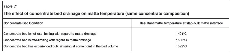
Eksteen12 has recently shown that when the gangue component median particle size becomes excessively fine, the concentrate bed on top of the slag becomes rate limiting with regard to early matte drainage, leading to rapid matte heat-up in the concentrate 'bed' before releasing the matte droplets for settling through the slag. Moreover, as fine particles tend to sinter very easily, sintering may lead to total lock-up of the base metal sulphides in the silicate and spinel matrix. This does not allow for early drainage of the matte, but rather a heat-up of the encapsulated matte until the surrounding silicate matrix completely breaks down, i.e. at its liquidus temperature. Therefore 'colder' furnace mattes are present only through thermal non-equilibrium. The earlier the matte melts and drains from the surrounding silicate matrix, the lower the incipient matte droplet temperature at the concentrate-slag interface. As the liquidus of furnace matte is around 850ºC, and the solidus of the silicate gangue minerals is around 1100ºC, with a gangue/slag liquidus of around 1450-1500ºC the matte can drain from the concentrate bed before incipient melting of the gangue can proceed. As shown by Eksteen)12, the critical drainage rate is determined by the theory of flow and energy transfer through packed beds. For a given median gangue particle size and concentrate 'black top' bed voidage, there is a critical superficial drainage velocity (mm/h or m3 matte/h/m2 concentrate bed). The critical superficial drainage velocity, in conjunction with the percentage matte fall, determines the maximum hearth power density (kW/m2) or maximum specific feed rate (kg/h/m2). Any hearth power density (or proportional specific feed rate) in excess of this maximum will lead to the concentrate bed becoming matte drainage rate limiting. For a given feed chemistry and slag temperature, Eksteen12has shown that, depending on particle size and the presence/absence of sintering, radical variations in matte temperatures may occur. A comparison of the different drainage scenarios is given in Table VI. A full description and derivation of the models used to predict matte temperature, along with a detailed example, is given by Eksteen12and is not repeated here.
It is therefore clear that, for UG2 concentrates, there are both upper and lower limits in terms of particle size.
It is clear that a jump of up to 100ºC in matte temperature can be obtained with the same bulk feed composition, but where the overall particle size distribution or the size-by-size distribution of minerals varies, leading to either free-draining cool matte or, at worst, hot matte derived from locked base metal sulphides in sintered gangue.
Eksteen's12 paper includes models for the droplet formation and matte droplet size in slag, the slag-to-matte droplet energy transfer, and the settling and equilibrium entrained matte volume fraction in the slag. Therefore, over and above the preheating of the matte in the concentrate bed, the slag composition, temperature, and circulation velocity determine the additional heating as droplets settle through the slag layer. The predictive model is free from any parameters fitted to industrial data. Therefore, the final model is based only on published sub-models and derived equations based on physical phenomena.
As the matte drainage model for matte temperature requires knowledge of matte fall (which is dependent on the concentration of total base metal sulphides in the feed) and the remaining gangue particle size distribution per size class (after matte melting and drainage), proper mineralogical information is required for the furnace feed; at minimum, a bulk XRD analysis and particle size distribution, but preferably a mineral liberation analysis. Not only does mineralogy help to determine the effect on matte temperature; it also helps to explain the release of corrosive gases such as sulphur vapour and halide vapours as well as condensable moisture, all of which are decomposition products of weathered/altered silicates. These corrosive gases have become much more problematic with the use of deep cooling devices with water cooling deep inside the furnace side-wall and close to the copper cooler hot face.
In summary, therefore, for a given electrode immersion and hearth power density, if UG2-rich concentrate is too coarse-sized, mush formation and build-up can occur. On the other hand, if the UG2 concentrate is too fine, the matte can easily overheat. UG2 particle size distribution, hearth power density, and electrode immersion are therefore interrelated for sustainable, safe, and stable furnace operation.
Mention has been made of the important role of electrode immersion. Direct control of immersion (where immersion itself is a continuously measured parameter) is currently still unfeasible. However, model-based prediction of immersion for a given furnace geometry, slag temperature, and composition (and therefore resistivity) is possible. This allows the prediction of the required resistance to maintain a given required immersion. This concept is dealt with by Georgalli et al.13and has been implemented at Lonmin in an off-line, procedural way.
UG2 impacts on converting and slag granulation
As mentioned previously, UG2-rich concentrate blends lead to low matte falls and smaller post-furnace converting and refining requirements, initially justifying the use of traditional, smaller batch Peirce-Smith converters over newer continuous converting and furnace-based slag cleaning. However, two aspects of furnace matte derived from UG2 smelting pose a significant challenge to the converter foreman:
High (2%-4%) dissolved Cr in furnace matte leads to severe chromite (FeCr2O4) precipitation during the oxidizing converting process. The precipitates accumulate as accretions around tuyeres, and can lead to more frequent plugging of the tuyeres. Consequently, more-than-usual punching of the tuyere-line is required, contributing to more rapid deterioration of the tuyere-line. Blocked tuyeres can rapidly lead to a mis-distribution of injected air, leading to local overoxidation in some parts of the bath, while other parts are poorly converted. The localized blocking of tuyeres is considered to further exacerbate poor longitudinal mixing in the converter, and changes the wave formation in the converter, which normally leads to increased amounts of slopping and splashing from the converter mouth. End-point control (visual or automatic) therefore becomes more problematic if all the tuyeres are not accretion-free. Converter campaign life can be as low as 20 blows, and is seldom more than 40 blows.
Another aspect of chromite precipitation from furnace matte, which is already present in the converter aisle, is the rapid formation of skulls in launders and ladles, leading to increased reverts formation, and therefore more re-work, and partial loss of immediately convertible matte.
The high matte temperature is another challenge for the converter refractory campaign life-unless the converter is preheated to quite high temperatures, the refractory will spall fairly rapidly from thermal cycling when it is loaded with furnace matte at temperatures above 1500ºC. As the tuyere line can already be weakened through frequent punching, this area of the vessel is further compromised by the thermal cycling.
Furnace design considerations
Originally, the high liquidus temperatures of UG2-based slags, and the settling of chromite to form build-up and mush, became the major drivers for building furnaces with high hearth-power densities. With the high anticipated sidewall energy fluxes, the need for intensive deep-cooled copper coolers was identified. Hatch, who handled the furnace design and EPCM functions at the time, proposed the use of their patented 'waffle' deep-cooled copper coolers, which formed a continuous ring around the furnace in the slag region. As a method to establish a slag freeze-line, these coolers were highly successful. However, a number of aspects of UG2 smelting in particular, and PGM smelting in a broader sense, were underestimated:
Through a process of considerable development, involving testing of different coating materials such as Hastelloy initially and later graphite, and through a collaborative interchange of information with Anglo Platinum, who experienced many similar challenges at their Polokwane furnace, some of these issues were addressed. Lonmin eventually decided on a hybrid design of plate coolers in the lower half of the sidewall, and graphite-faced waffle coolers in the upper sidewall. While some of the benefits of the waffle coolers are sacrificed with the use of plate coolers, Lonmin preferred the foreseen predictability of sidewall monitoring through the refractories, over the promise of optimal cooling. Gap formation between the refractory skews and waffle coolers also assisted in the decision to opt for the hybrid design. Lining management (monitoring) systems (LMS) and taphole monitoring systems have been implemented through the use of fibre-optic temperature monitoring. Extended areas of the copper coolers and tapholes, are monitored using LMS, and thermocouples are used in abundance in the refractory sidewalls. An online pressure-test system has also been implemented in order to detect water leaks as a result of cooler corrosion and wear.
The significant movement of the hearth refractories, particularly due to the high process temperatures and the significant variability in matte temperature, led to much effort going into refractory design, layout, and quality assurance during manufacturing and installation. To minimize thermal cycling and refractory movement, Lonmin has moved towards a maintenance strategy (particularly on tapholes) of hot repair. This, in turn, has some implications for taphole positioning and design.
Matte-fall variations can occur rapidly when plugs of high base metal content material sporadically enter the concentrate bed. Responding fast enough to rapid matte rise in the furnace can be a challenge if the tidal-zone inventory is not sufficient to prevent the matte from reaching the level of the copper coolers. The design of a robust tidal zone is essential to furnace reliability. Knowing the position of the matte-slag interface is of key importance, with traditional sounding being found to be inadequate to predict matte levels, particularly when some mush has accumulated. The implementation of the Agellis system, described by Goff et al.14for interface detection, and the integration of the Blue Cube sensor system in the furnace feed into matte-level prediction are anticipated to go a long way in aiding production staff to manage matte-slag interface levels.
As Eksteen12 has shown mathematically, the particle size distribution of UG2-rich blends constrains the hearth power densities of electrical furnaces via the matte drainage rate and concentrate-bed porosity. The more UG2 is present in the concentrate blend, the greater the role of particle size (at both the too-coarse and too-fine ends of the scale). For pure Merensky or low-UG2 blends, this is considered to not present a problem.
Lastly, the furnace geometry choice is also related to the regime of smelting high concentrations of UG2. For Lonmin, a large part of the choice to continue with a circular furnace design is based on successful historical and operational development. Thus, originally, from the successes with the small circular Pyromet furnaces and the cumulative experience from No. 1 Furnace, it was decided to stick with the 'devil we knew', warts-and-all. From CFD modelling of six-in-line and circular furnaces, there are distinct advantages in using circular furnaces from a process metallurgical perspective. On the other hand, there are sufficient mechanical reasons to argue why a six-in-line furnace, might be the most suitable from this perspective (hold-down, tap-block movement, and the sprung arch roof).
Conclusions
The road to smelting higher concentrations of UG2 concentrates has been a rocky one, with many unforeseen turns. While small scale (< 5 MW) smelting of UG2-rich blends was relatively easily mastered, the scale-up in furnace power rating was found to be in no way obvious. It became clear that, among other factors, a good understanding of the rate processes was essential. These rate processes, such as local flow velocities of slag and matte (predicted through CFD), drainage rates of matte through furnace concentrate 'beds', settling rates of matte droplets, and energy transfer in the various regions of the furnace, are complex phenomena that are not easily modelled through empirical regression of plant data. In addition, the types of reliable data needed (and measured at a suitable frequency) in order to model furnace behaviour are typically scarce at the smelter. A concerted effort is required through tedious sampling campaigns and detailed analyses of materials down to the size-by-size mineralogy, and then this defines only the initial and boundary conditions. Matte smelting of high-UG2 concentrate blends requires insight into a complex interaction of feed mineralogy, process dynamics, particle technology, and furnace design and process control, as described in this paper. This all has to be done with the human element in mind, taking into consideration the ability of operators to respond to process upsets.
It is also clear that the challenges with UG2 smelting do not end with the furnace operation, but can have downstream impacts on the converting and refining operations also, as mentioned in this paper.
References
1. STEENEKAMP, N. and DUNN, G.M. Operations of and improvements to the Lonrho Platinum Base Metal Refinery. Proceedings of the EPD Congress, 2009, B. Mishra, (ed.) The Minerals, Metals and Materials Society, Warrendale, PA, 1999. pp. 365-378. [ Links ]
2. DORFLING, C., AKDOGAN, G., BRADSHAW, S.M., and EKSTEEN, J.J. Determination of the relative leaching kinetics of Cu, Rh, Ru and Ir during the sulphuric acid pressure leaching of leach residue derived from Ni-Cu converter matte enriched in platinum group metals. Minerals Engineering, vol. 24, no. 6, 2011. pp. 583-589. [ Links ]
3. CHAITRAM, K. and RADEMAN, J. Lonmin improves smelter efficiency, Advanced Process Control. MMS Mag, July 2008. pp. 23-25. [ Links ]
4. THYSE, E.L., AKDOGAN, G., and EKSTEEN, J.J. The effect of changes in iron endpoint during Peirce Smith Converting on PGE containing nickel converter matte mineralisation. Minerals Engineering, vol. 24, no. 7, 2011. pp. 668-697. [ Links ]
5. VAN SCHALKWYK, R.F., EKSTEEN, J.J., PETERSEN, J., THYSE, E.L., and AKDOGAN, G. An experimental evaluation of the leaching kinetics of PGM-containing Ni-Cu-Fe-S Peirce Smith converter matte, under atmospheric leach conditions. Minerals Engineering, vol. 24, no. 6, 2011. pp. 524-534. [ Links ]
6. PERSSON, W., WENDT, W., and DEMETRIO, S. Use of optical on-line production control in copper smelters. Proceedings of Copper 99/Cobre 99. Volume V. Smelting Operations and Advances, The Minerals, Metals and Materials Society, Warrendale, PA, 1999. pp. 491-503. [ Links ]
7. PERSSON, W. and WENDT, W. Optical spectroscopy for process Monitoring and production control in ferrous and nonferrous industry, Proceedings of Materials Science and Technology 2003-Modelling, Control and Optimization in Ferrous and Nonferrous Industry, Chicago, 9-12 November 2003. pp. 177-191. [ Links ]
8. BEZUIDENHOUT, G.A., EKSTEEN, J.J., and WENDT, W. Endpoint control in PGMcontaining nickel matte converting using flame emission spectroscopy. Processing of Nickel Ores and Concentrates '10. Falmouth Beach Hotel, Falmouth, UK, 17-18 June 2010. Minerals Engineering International, 2010. [ Links ]
9. Ritchie, S. and Eksteen, J. Investigating the effect of slag bath conditions on the existence of "mushy" zones in PGM smelting furnaces using computational fluid dynamics. Minerals Engineering, vol. 24, no. 7, 2010. pp. 661-675. [ Links ]
10. BEZUIDENHOUT, G.A., EKSTEEN, J.J., and BRADSHAW, S.M. Computational fluid dynamic modelling of an electric arc furnace used in the smelting of PGM containing concentrates. Minerals Engineering, vol. 22, no. 11, 2009. pp. 995-1006. [ Links ]
11. FONSECA, R.O.C., CAMPBELL, I.H., ST.C. O'NEILL, H., and FITZGERALD, J.D. Oxygen solubility and speciation in sulphide-rich mattes. Geochimica et Cosmochimica Acta, vol. 72, 2008. pp. 2619-2635. [ Links ]
12. EKSTEEN, J.J. A mechanistic model to predict matte temperatures during the smelting of UG2-rich blends of platinum group metal concentrates. Minerals Engineering, vol. 24, no. 7, 2010. pp. 676-687. [ Links ]
13. GEORGALLI, G.A., EKSTEEN, J.J., BEZUIDENHOUT, R., VAN BEEK, B., and GOFF, T.J. Towards electrode immersion control on Lonmin's no. 1 circular furnace. Journal of The Southern African Institute of Mining and Metallurgy, vol. 109, no. 1, January 2009. pp. 53-64. [ Links ]
14. GOFF, T.J., BROGDEN, N., NILSSON, J.P., BLOEMER, P., and LYONS, A. Implementation of an alternative matte level measurement solution at Lonmin Marikana Smelter Division for improved process monitoring. Southern African Pyrometallurgy 2011. R.T. Jones and P. den Hoed, (eds.), Johannesburg. The Southern African Institute of Mining and Metallurgy, 6-9 March 2011. pp. 269-284. [ Links ] 
This paper was first presented at the Southern African Pyrometallurgy Conference, 6-9 March 2011, Misty Hills, Muldersdrift.
© The Southern African Institute of Mining and Metallurgy, 2011. SA ISSN 0038-223X/3.00 + 0.00.

