


Services on Demand
Article
 English (pdf)
 Article in xml format
 Article references
Indicators

Related links
-
 Cited by Google
 -
 Similars in Google
Share

 Permalink
Journal of the Southern African Institute of Mining and Metallurgy
On-line version ISSN 2411-9717
Print version ISSN 2225-6253
J. S. Afr. Inst. Min. Metall. vol.111 n.10 Johannesburg Oct. 2011
TRANSACTION PAPER
Some myths about DC arc furnaces
R.T. JonesI; Q.G. ReynoldsI; T.R. CurrI; D. SagerII
IMintek, Randburg, South Africa
IIABB Switzerland Ltd, Turgi, Switzerland
SYNOPSIS
DC arc furnaces are widely used for steel scrap melting as well as for reductive smelting of ore fines. Industrial smelting applications include the smelting of chromite to produce ferrochromium, the smelting of ilmenite to produce titania slag and pig iron, and the recovery of cobalt from nonferrous smelter slags. A number of myths and misconceptions are widely held, especially regarding: the age of the technology, the use of a hollow electrode, arc stability and shape, arc and bath radiation, interaction between the arc and molten slag, electrical behaviour of arcs and slags, a comparison between AC and DC furnaces, DC reactors, the lifespan of bottom electrodes, and the applicability of DC arc furnaces to various metallurgical systems.
Keywords: pyrometallurgy, DC arc furnace, myths, history, hollow electrode, radiation, resistance, flicker, AC.
Introduction
DC arc furnaces have been known by various names over the years. In this paper, a 'DC arc furnace' refers to a pyrometallurgical vessel that comprises a cylindrical steel shell with either a domed or flat base, and a roof that is typically conical. It is lined inside with a refractory material in order to contain the molten materials being processed. The furnace usually has a central graphite electrode (occasionally more than one, but that is not the specific focus of this paper), and an anode embedded in the hearth. It is usual that the molten metal in the furnace is in electrical contact with the anode. Energy is supplied to the furnace by means of an open plasma arc that impinges on the upper surface of the molten material. The arc in a DC (direct current) furnace is a sustained high-velocity high-temperature jet, driven by electromagnetic acceleration (the Maecker effect) in the constricted region near the arc's root on the electrode surface. The arc is generated by the interaction between the fluid flow, the thermal field, and the electromagnetic fields. The self-constricting electromagnetic forces keep this supersonic super-heated plasma jet reasonably coherent. A DC reactor is used to stabilize the arc further. Furthermore, the surface of the molten bath (or at least a portion of the surface in the arc attachment zone) is open, i.e. essentially uncovered by unreacted feed material.
These open-arc open-bath DC furnaces have a number of advantageous properties, and are increasingly being applied in the metallurgical industry. However, there remain many misunderstandings about the technology. The views and stereotypes of popular belief might well have an explanatory purpose, but not all are correct. It is hoped that this paper will assist in clearing up some of the myths about DC arc furnaces.
Myth 1: DC arc furnace technology is new and unproven
DC arc furnaces have been used for the bulk melting of metals since at least 1878, when Sir William Siemens1used a DC arc furnace with a vertical graphite cathode, with the arc transferred to the melt in contact with a watercooled bottom anode. In contrast to this, the first AC electric arc furnace (invented by Paul Héroult and patented in 1900) was first operated in La Praz, France, in 1900. Electric furnace technology became almost entirely ACbased thereafter, because of the use of AC for efficient power transmission from large central power stations (following developments by Nikola Tesla and George Westinghouse in 1887 and 1888) and the use of local stepdown transformers to supply the high currents required in the furnaces.
Significant commercialization of DC furnace technology occurred in the 1990s, when there was a huge demand for DC arc furnaces for steel scrap melting, following the development of high-power solid-state rectifiers. Around that time, about 80 DC arc furnaces were built in the northern hemisphere. Apart from extensive use in the steel industry, it is only in the past few decades that DC arc furnaces have been used for smelting processes, where the feed materials are predominantly nonmetallic and significant chemical reactions are involved. Mintek's Pyrometallurgy Division has been fortunate enough to be involved in the industrial-scale commercialization of roughly one application of this technology per decade, and has become well known internationally for its work on DC arc furnaces2. This started with the smelting of chromite ore fines to produce ferrochromium in the 1980s, and was followed by the smelting of ilmenite to produce titania slag and pig iron in the 1990s. In both of these cases, the process chemistry was well known and the products were familiar (albeit with some minor variations), even though the type of furnace was novel at the time. A further example was the use of a DC arc furnace to recover metals (principally cobalt) from nonferrous smelting slags3,4 early in the 2000s. In this case, a new process was carried out in a 'new' piece of equipment to produce a somewhat unfamiliar intermediate product. This, therefore, required testing and demonstration at quite a large scale. There are currently another two applications of DC arc furnace technology that are poised on the brink of commercialization-namely the smelting of nickel laterite to produce ferronickel, and the ConRoast process5, which can be used for the smelting of both platinum group metal (PGM) and nickel sulphide ore concentrates.
Myth 2: DC arc furnaces need a hollow electrode and stabilizing gas
The first conceptual DC arc furnace for smelting applications6envisaged a hollow graphite electrode as a feed chute to place the feed material in the highest temperature zone of the slag surface. In the early 1980s, Mintek interacted with ASEA in Sweden and Lurgi in Germany regarding the ELRED process for ironmaking. The ELRED process was based on a hollow graphite electrode and this approach offered much greater scale-up potential than the proposed water-cooled plasma torches at that time. In 1985, the first commercial DC arc smelting furnace treating chromite fines used the hollow graphite electrode feeding arrangement, as did all subsequent DC arc smelting furnaces built over the next 15 years. It is widely thought that by feeding through the hollow electrode, the feed materials will also pass through the plasma making up the arc column and thereby be exposed directly to the high temperatures typical of these plasmas i.e. > 10 000 K. As it has been shown that the arc attaches to the electrode in a high-intensity spot (~3.5 kA/cm2)7that moves rapidly over the relatively large surface of the graphite electrode tip (the cathode) as well as over the surface of the molten slag surface (the anode), to maintain the lowest resistance path, it is probable that the arc column will move away from the relatively cold and high-resistance feed materials. The high velocity and viscosity of the gas in the arc column make it difficult for solid particles to become entrained into the arc column. Plasma spraying and coating applications usually use a water-cooled plasma torch arrangement whereby the solid particles are injected through the torch assembly into the region close to the arc attachment spot so that the Maecker8effect can entrain them into the arc column. It is also often assumed that a hollow graphite electrode feed arrangement is essential to avoid large losses of entrained finely sized feed materials to the gas stream leaving the furnace through the off-gas port.
However, it was clear that it would be advantageous to avoid the additional manufacturing cost of a hollow electrode as well as the additional complexity of attaching the feed chute to the top of the electrode column, including provision of an inert gas (usually nitrogen). This gas was required to prevent hot furnace gases from entering the feed system and was also thought to improve the stability of the arc itself.
Consequently, in 1996, Mintek investigated the effects of feeding bag-plant dust through a hollow graphite electrode compared with feeding it through ports in the roof. These ports were located less than 500 mm from the centre of the 200 mm solid graphite electrode. It was found that, even with these very finely sized materials (100% < 20 µm), there were no significant metallurgical differences in smelting behaviour, and the percentage of feed materials reporting to the furnace gas-cleaning plant increased only from 4% to 7%. Subsequent experiments with larger-sized feed materials such as chromite (D50 of 0.5 mm) showed an increase in dust losses of less than 1% of the feed material. No negative effect was noticed on the stability of the arc, despite the absence of the nitrogen gas down the electrode.
The first commercial DC arc smelting furnace to utilize solid graphite electrodes and roof feed ports was the 40 MW furnace at Chambishi Metals3,4 in Zambia in 2001, based on the Mintek pilot-plant testwork with this arrangement (known as side-feeding). Subsequently, some of the DC furnaces originally installed with hollow graphite electrode feed systems have adopted side feeding, and this trend is expected to continue.
Myth 3: The arc is a steady cylindrical column of hot gas
A commonly held view is that the arc inside a DC plasma arc furnace is a steady-state phenomenon. In literature on the subject, the arc column is often shown as having a cylindrical, symmetric shape and taking the shortest path between the end of the electrode and the surface of the molten bath beneath. Many of the mathematical and numerical modelling methods used to study plasma arcs also promulgate this impression by discarding the time-dependent terms in the governing equations, and using cylindrical coordinate systems which impose symmetry on the system.
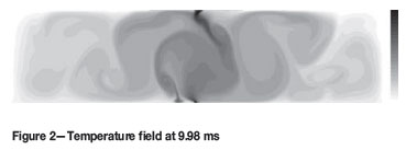
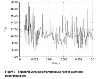
Recent work in this area7has shown that plasma arc models developed using explicit time dependence and Cartesian coordinate systems are able to display a wide range of dynamic motion and asymmetric behaviour, with the arc column becoming twisted and deformed into complicated irregular shapes over very short time scales (milliseconds or less). Some examples of this are given in Figures 1 and 2, which show the temperature field (scale 2000-15 000 K) in the model at various times. The arc length is 5 cm, and the arc current is 500 A. The time dependence of the temperature field in the model is shown in Figure 3.
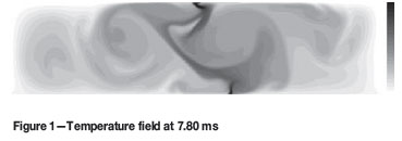
In the dynamic models, the nature of the time-dependent behaviour is also seen to vary strongly with operating parameters such as arc length and current. At shorter arc lengths and low currents, stable and steady arcs are generally formed. As the arc length (or the current) is increased, regular oscillations begin to occur, originating from a rapid precession of the arc jet around the attachment point on the electrode surface. This precession motion twists the arc column into a dynamic helical shape. Further increases in arc length and current produce another transition in temporal behaviour, from regular oscillations to chaotic and unpredictable motion of the arc.
Similar transitions have been observed in experimental work using a high-speed video camera to record arc motion at very short time scales9. At low currents, the arc column is 'classical', cylindrical, and steady in time. An example image is shown in Figure 4.
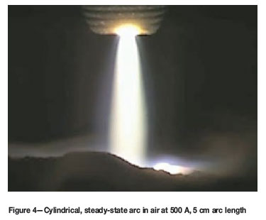
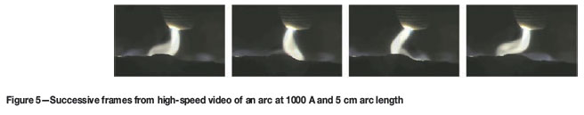
As the arc current is raised to 1000 A, the column begins to exhibit time-dependent behaviour in the form of regular oscillations. A sequence of successive frames from highspeed video of an arc at 1000 A and 5 cm arc length is shown in Figure 5.
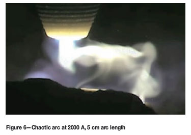
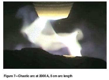
Finally, as the current is raised to 1500 A and beyond, the regular motion of the arc breaks down into chaotic, irregular motion. The arc column takes on complex geometrical shapes during this behaviour. Some example frames from high-speed video of an arc at 2000 A and 5 cm arc length are shown in Figures 6 and 7.
Recent work in the field of both theoretical and experimental study of DC plasma arcs has therefore shown that the recognition of short-term transient effects is significant in order to gain a complete understanding of the arc system. Small-scale studies, such as those relevant to arc welding or laboratory-scale DC furnaces, often present the arc as being cylindrically symmetric and at steady state. However, this condition is not stable once the scale of the system increases to pilot plants and beyond, as the increased current and dimensions of the arc result in the arc becoming a highly dynamic, time-dependent phenomenon.
At present, the largest DC arc furnace for smelting applications is the 60 MW ferrochromium furnace at Middelburg10. The stirring caused by the DC plasma arc has been found to be advantageous in terms of mixing the fine feed materials into the molten slag bath. At industrial current levels, the velocities in the arc can reach many kilometres per second, and this imparts a significant thrust force to the surface of the molten slag or metal bath beneath. Interaction between the arc jet and the molten bath results in a great deal of turbulent splashing and mixing, stirring the bath and homogenizing its properties to a large degree.
Myth 4: Radiation from the arc is overwhelming
It is frequently assumed, because the direct-current plasma arc operates at extremely high temperatures (10 000- 20 000 K), that the emission of thermal radiation completely dominates all energy transfer within the freeboard space of a DC arc furnace. Although thermal radiation from the hot arc plasma is indeed a significant phenomenon, it is important to clarify what happens to the majority of this radiation once it is released.
Treating the plasma gas as a black body radiator can produce misleading results. This calculation is easily performed, and relates the volumetric energy emission to the temperature and radius of the emitting volume, as shown in Equation [1].
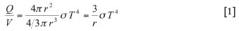
where:
Q/V = Volumetric rate of energy loss, W/m3
r = Radius of emitting volume in plasma, m
σ = Stefan-Boltzmann constant, 5.67 x10⁻⁸ W/m2K4
T = Plasma temperature, K
Boulos et al.11present calculations of the actual emission of energy from thermal plasmas by radiation, based on fundamentals of plasma physics, taking into account absorption and many other effects. Their results are comparable with experimental measurements of the same gas systems. For comparison, the volumetric emission calculated from Equation [1] for black body radiation is shown in Figure 8, while the data from Boulos for a nitrogen plasma is shown in Figure 9. (Note that, in these figures, 'ster' is the standard abbreviation for the SI unit of solid angle, the Steradian.)
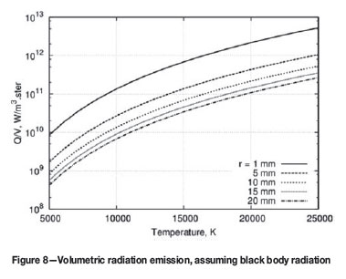
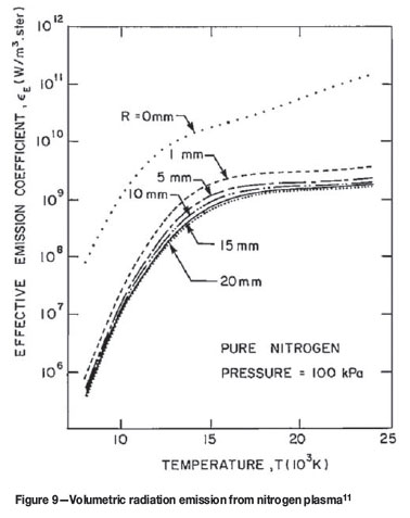
It can be seen that even when an optically thin plasma (no absorption, R=0) is considered, the emission of thermal radiation from an arc plasma can be well over ten times lower than the smallest numbers predicted by black body methods. If, in addition, the re-absorption is considered over distances of 10 to 20 mm (typical for plasma arcs at pilot-plant or larger scales), the thermal radiation emission drops off by a further two to three orders of magnitude. As a result of this, a large fraction (>99%) of the radiation emitted by the plasma in the arc is re-captured in the body of the arc before it escapes into the freeboard. The arc jet directs this energy very strongly down at the molten bath surface, where it can be transferred directly to the bath material by close-proximity radiation, convection, and conduction. The arc is therefore extremely efficient at converting electrical energy into thermal energy and delivering it into the molten bath directly beneath the electrode, without losing too much to the furnace sidewalls and roof in the process.
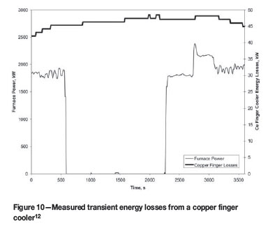
Experimental evidence supporting the radiation from the hot bath surface as the primary mechanism of heat transfer to the freeboard surfaces in the DC arc furnace has been published previously12.
Figure 10 shows measured data from a copper finger cooler inserted into the freeboard space of a pilot-plant furnace. Due to the very high thermal conductivity of copper, its response to changing energy flux from the furnace freeboard would be expected to be very rapid. As can be seen, the shutdown of power at 600 s results in virtually no change in the measured energy losses at the cooler over a significant period of time (25 min). This supports the conjecture that it is radiation from the bath surface, and not directly from the arc, that is the dominant effect within the freeboard spaces of DC arc furnaces.
Myth 5: The arc punches a hole right through the slag
In the same way that a jet of compressed air can displace water, so it is reasonable to expect that a plasma arc should be able to displace some of the slag onto which it impinges. Of course, the real question is: how much is displaced?
Bowman13quotes the work of Maecker8that shows the thrust of the arc to be proportional to the square of the current, as shown in Equation [2].

where:
T = arc thrust, N
I = arc current, kA
Assuming that the shape of the cavity is a paraboloid with radius r and height or depth h, the volume V of the displaced slag may be expressed as:
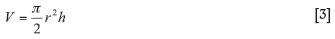
The thrust of the arc may be equated to the buoyancy force generated by the absence of slag from the cavity (i.e. the volume multiplied by the slag density and gravitational acceleration).
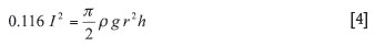
where:
ρ = slag density, kg/m3
g = standard gravitational acceleration, 9.81 m/S2
The shape of the depression in the arc attachment zone (AAZ) is defined by the formulae for the diameter and depth in Equations [5] and [6] respectively, where ψis the diameter to depth ratio.
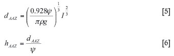
Figure 11 shows the dimensions of the arc cavity that is formed, under different assumptions of the diameter to depth ratio. A ratio of 6:1 is based on our assessment of typical arc depressions seen in photographs of arcs from the Mintek pilot plant, and a ratio of 1:1 is the stability limit14 for gas jets impinging on liquid surfaces.
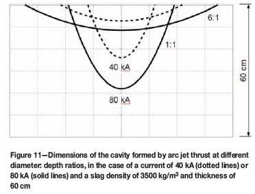
The 1:1 ratio is an extreme case, and the 6:1 ratio is more likely. For slags of reasonable density and moderate depths (typically around 60 cm), it is very unlikely that all of the slag is blown away by the arc, even when the current is very high.
Myth 6: A DC arc furnace is a constant-resistance device
The electrical behaviour of a DC arc furnace may be modelled as an arc in series with a layer of slag. The arc has a particular resistivity for a given gas composition and
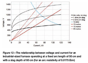
temperature. For example, a value of 0.015 to 0.020 Ωcm is typical for a furnace atmosphere rich in carbon monoxide at a temperature around 1600ºC. Following the approach of Bowman13, the voltage across the arc is modelled as a function of arc length and current15. The voltage across the slag is calculated by solving the Laplace equations for the assumed geometry of the slag (with the arc depression taken into account) and an assumed distribution of current at the upper surface16. The slag voltage is directly proportional to the resistivity of the slag (which is, in turn, a function of composition and temperature). It is important to note that the voltages across the arc and the slag are both nonlinear with current.
Figure 12 shows the relationship between voltage (V ) and current (I ) for a hypothetical 70 MW furnace operating with a fixed slag depth and arc length. The constant-power curve is hyperbolic in shape, resulting from the relationship P = V I. Constant-resistance lines, resulting from the relationship V = I R, are shown in the diagram in order to contrast with the calculated shape of the actual relationship between voltage and current. The lowest of the nonlinear curves illustrates the behaviour of the arc on its own (i.e. equivalent to a slag with zero resistivity), and the other two curves show the additional voltage resulting from slags of different resistivities (1 and 2 Ωcm respectively).
The design of the power supply for a DC arc furnace needs to take into account possible variations in arc length, slag depth, and slag resistivity (which is affected by slag composition and temperature). A number of voltage-current relationships need to be plotted, taking into account the range of variables being designed for, and a suitable operating window can then be specified.
The theoretical model introduced above has been used extensively to improve the understanding of the operation of pilot-plant furnaces at Mintek. Further confirmation of the validity of the model can be found by noting the good qualitative agreement between the shape of the theoretical curve16for voltage versus arc length, and the recently published measured curve for voltage versus arc length obtained from an industrial 60 MW furnace producing ferrochromium10.
Of course, the ultimate question of whether a DC arc furnace is a constant-resistance device would be answered by plotting voltage versus current (for a fixed set of conditions including arc length, bath depth, composition, and temperature) for an industrial furnace running from low to high current. The publication of such data is eagerly awaited.
One should also keep in mind that DC arc furnaces are powered by thyristor rectifiers, which allow for very fast and automatic adjustment to short-term variations in furnace conditions and enable the furnace to be operated at a specific resistance set-point, if this method of control is selected.
Myth 7: New technology in AC furnaces makes DC furnaces redundant
It is true that, for steelmaking, AC arc furnaces to melt scrap are enjoying a growing popularity over the DC arc furnace for some practical advantages, but the physics has not changed17. The AC arc furnace's current cannot be kept 100% symmetrical; its power factor is poorer; power on/off is achieved through switching of the furnace transformer; and, while arcing, the AC arc furnace always generates more flicker than a DC arc furnace. This might not be much of an issue in cases where a) the furnace is not very big and b) where the supplying electrical grid is strong (high shortcircuit capacity).
Neither the steel industry nor the ferroalloy industry is typically located close to a major cosmopolitan hub with 20 GW of electrical power generation just nearby. No, this industry is often far away from a large power generation plant. Through the long transmission line required to supply the electrical power to the plant site, the short-circuit capacity of the grid deteriorates over distance, and hence the grid is more and more prone to disturbance by flicker generated in the arc furnace.
As electrical utility companies need to deliver clean electrical power to the nearby town or other industrial plants, they often enforce stringent requirements of power quality on all their customers. This means that all flicker and harmonic current that originates from the electric-arc operation needs to be 'cleaned up' on the plant site. The more stable the arc, the less flicker and harmonic current is produced. Additionally, reactive power load swings could cause voltage fluctuation with a magnitude of ± 10% at high voltage level. The furnace's operation at poor power factor also has a negative impact on power quality. All these phenomena are the more problematic the weaker the power grid is at coupling to the plant site. They could escalate to a magnitude where it becomes impossible to operate a large (more than 50 MW) arc furnace.
However, there are a number of corrective means that enhance power quality and enable arc furnace operation even on a weak grid (Sfurnace < 25 x Scc-HV). There is the Static Var Compensator (SVC), which allows for constant voltage control on the furnace MV-bus with the help of a thyristorcontrolled reactor while keeping the power factor in the required limit and cancelling the harmonic currents at the same time18. Should power quality targets still not be achieved, an even more effective tool, the voltage source converter (VSC), is at hand; this (in simple terms) uses advanced power electronics, an Insulated gate bipolar transistor (IGBT) stack, for keeping the MV voltage constant (flicker mitigation) and enhancing the power quality.
But, in all cases, a strong improvement in power quality on the weak grid is achieved through choosing DC technology instead of AC. The DC arc furnace operates at a better power factor; switching transients from energizing the furnace transformer can be completely eliminated, and the flicker seen on the MV-bus is approximately half as severe.
Only feasible with a DC arc furnace is a technology called 'shift-control', also known as 'split-alpha operation mode'. By controlling the firing angles of a four-rectifier DC power supply according a special algorithm, flicker on the HV-bus can be further reduced by a factor of 1.5 while, at the same time, also reducing the reactive power and harmonic current generated.
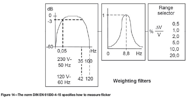
What is flicker?
Flicker is a non-periodical voltage fluctuation visible to the human eye. It is defined and quantified through the frequency response to sinusoidal voltage fluctuations of a coiled filament gas-filled lamp (60 W, 230/120 V) combined with the human visual system. The response function is based on the perceptibility threshold found at each frequency by 50% of the persons tested, which results in a weighting curve with 8.8 Hz found to be most dominant.
The units of the flicker are the following:
Pst_95 (Perturbation Short Term) Interference factor during 10 min with 95% of the measured samples staying within the limit.
Flicker is normally measured at the PCC (Point of Common Coupling) on High Voltage. A typical limit requested by the utility is Pst_95 = 1.0
Audio noise
A further advantage of DC furnaces when used for scrap melting is the reduction in audio noise relative to AC furnaces.
Myth 8: The DC reactor in the power circuit causes flashovers/stray arcing
No! The DC reactor is basically an energy storage device. Some typical values for a ferroalloy DC arc furnace would be
This is not very much energy, but normally enough to keep the arc reasonably stable. By no means could one 'suddenly' interrupt an arc; that theoretically would result in an infinitely high voltage from the DC reactor. Whether it is a scrap cave-in or an electrode breakage, there is always enough time to gradually discharge the energy of the DC reactor through the arc which is established already, or through a new one in case of an electrode breakage, such that practically no DC voltage increase can be seen. Although one second might appear as an instant to our eyes, electrically speaking this is a lot of time, representing 50 or 60 entire cycles, in which control systems can take about 500 corrective actions.
In any case, the DC power supply should also be equipped with over-voltage protection that shorts high-voltage transients (e.g. from transformer energizing) to ground immediately for protecting the thyristors.
There has also been much concern about flashovers (also known as stray arcing) to the furnace shell, particularly to the furnace roof. This is somewhat critical where the slag is very conductive, for example TiO2 slag, but less important in the case of the highly resistive slags such as those found in ferronickel smelting or cobalt recovery from slags. With a proper design of the furnace, correct isolation of the roof hole from the electrode, and an optimized feeding system, a flashover does not occur.
Keep in mind that, under normal circumstances, the liquid bath in the furnace is the arc's lowest resistance ('shortest path') to the rectifier's 0 V potential through to the anode in the furnace bottom, and hence the arc has no 'motivation' to take a longer route via the furnace roof.
And should it still happen, for whatever reason, by a high-speed potential monitoring of the furnace roof and/or shell, the rectifier control could detect a flashover within 20 ms and immediately take corrective action in order to prevent any damage to the furnace.
However, stray arcing is also a well-known phenomenon on AC arc furnaces, where the liquid bath needs to be kept isolated from ground, but with the difference that one cannot take very fast corrective actions without tripping the furnace's breaker.
Myth 9: The bottom electrode has a short life and is costly to maintain
Since the invention of DC furnace technology, the bottom anode of the furnace has been considered one of the most critical parts. Different equipment manufacturers came out with a variety of different anode designs. At the beginning, equipment manufacturers concentrated mainly on scrap-melting applications, always with a focus on the maintenance costs and the metallurgically required lifetime. The three main designs finally accepted on the market were the fin-type electrode from VAI Fuchs, the pin-type electrode from the SMS Group, and the conductive bottom electrode from ABB (which, after ABB divested its arc furnace business to Concast, was also claimed by the SMS Group). The first two electrode types are, without doubt, the best solution for steelmelting furnaces, taking into account the required lifetime and cost of maintenance. For small smelting furnaces, the multi-pin type anode has proved to be a reliable solution.
For industrial DC smelting processes, it can be said that the conductive bottom electrode provides a number of advantages to the process and furnace operation, and it is no longer the 'headache' of DC technology as many people once regarded it when comparing DC with AC technology. Because furnaces require very expensive refractory materials, the lifetime of the furnace is often of paramount importance. As the smelting process is a nearly continuous process, and there is generally no direct contact between slag and hearth, this type of bottom electrode provides the longest lifetime for the DC smelting operation. Depending on the use of the furnace, today's bottom electrodes can have a lifetime of 5 to 10 years, without requiring any maintenance. Until recently, the conductive bottom hearth was protected by a patent, but is now available for public use.
The conductive bottom electrode consists of a copperplated steel plate covered by metallized bricks. This ensures conductivity even if local spots are covered by nonconductive material, and uses bricks to withstand the metallurgical impact. Another advantage of using bricks is that the metal part of the bottom electrode requires only aircooling. Compared to other water-cooled systems, this presents an important safety advantage.
Myth 10: The DC arc furnace is a solution to all metallurgical problems
DC arc furnaces have some wonderful features. They are very good at accommodating finely sized feed materials (because of the open bath), and they do not require the use of coke or char. They allow for the treatment of feed materials with a wide variety of composition (because of the extra degree of freedom coming from the relative independence of the power supplied by the open plasma arc). They are geometrically simple and elegant, which reduces costs associated with complex roof designs and uneven wear on sidewalls. However, it is important to take cognisance of the effect of the hot off-gas on thermal efficiency, and of the absence of a burden that could otherwise assist in capturing volatile species that might fume off the molten bath.
DC arc furnaces have been found to be well suited to reductive smelting processes, such as those used for treating chromite, ilmenite, and nickel laterite ores, oxidized concentrates, and slags. On the other hand, it is not so clear that DC arc furnaces are well suited to pyrometallurgical processes requiring oxidizing conditions, or those that involve a gaseous intermediate such as SiO, or those that might bring a low-melting product into contact with a bottom anode. There is room for many types of furnace, and for wise choices to be made with regard to the most appropriate technology for a particular process.
Conclusions
DC arc furnace technology has existed since 1878, and has been well proven for a number of applications. Early DC arc smelting furnaces were fed through hollow graphite electrodes, but it has been found that close feeding around the arc has essentially the same result while saving on the cost of electrodes. The plasma arc is a highly dynamic phenomenon, with the arc moving extremely rapidly, often in a helical shape, or exhibiting chaotic irregular motion. Thermal radiation from an arc does exist, but it is often dominated by the thermal radiation from the open upper surface of the molten slag bath. The thrust exerted by the arc on the liquid slag is proportional to the square of the current, and this creates a depression in the slag; however, the slag is usually deeper than this depression in smelting furnaces.
The electrical behaviour of a DC arc furnace may be modelled as an arc in series with a layer of slag; the voltage is very nonlinear with respect to the current, and the behaviour is certainly very different from that of a constant-resistance device. DC furnaces have a number of electrical advantages over AC furnaces, especially in the case of a weak electrical grid. The more stable DC arc produces less flicker and harmonic current. The DC reactor stabilizes the arc by means of energy storage, but this can be done in such a way as to avoid flashovers. Robust hearth designs exist that provide long lives for anode connections. DC arc furnaces provide a number of very significant metallurgical advantages, especially in being able to treat fine feed materials, and in not requiring the use of metallurgical coke.
DC arc furnaces are not a panacea for all metallurgical problems, but are very well suited to a number of reductive smelting processes. They have been applied successfully in a number of industrial contexts, and many further applications are expected.
Acknowledgements
This paper is published by permission of Mintek and ABB, with the support of the National Research Foundation. The contributions and helpful comments of our colleagues are gratefully acknowledged.
References
1. English patents, No. 4208 of 1878 and No. 2110 of 1879. [ Links ]
2. JONES, R.T., BARCZA, N.A., and CURR, T.R. Plasma developments in Africa. Second International Plasma Symposium: World progress in plasma applications. Organized by the Electric Power Research Institute, Center for Materials Production, Palo Alto, California, 9-11 February 1993. http://www.mintek.co.za/Pyromet/Files/PlasmaDev.pdf [ Links ]
3. JONES, R.T., DENTON, G.M., REYNOLDS, Q.G., PARKER, J.A.L., and VAN TONDER, G.J.J. Recovery of cobalt from slag in a DC arc furnace at Chambishi, Zambia. Journal of the Southern African Institute of Mining and Metallurgy, vol. 102, no. 1, January/February 2002. pp. 5-9. http://www.mintek.co.za/Pyromet/Files/Chambishi.pdf [ Links ]
4. NELSON, L.R., SULLIVAN, R., JACOBS, P., MUNNIK, E., LEWARNE, P., ROOS, E., UYS, M.J.N., SALT, B., DE VRIES, M., MCKENNA, K., VOERMANN, N., and WASMUND, B.O. Application of a high-intensity cooling system to DC-arc furnace production of ferrocobalt at Chambishi. Journal of the Southern African Institute of Mining and Metallurgy, vol. 104, no. 9, October 2004. pp. 551-561. http://www.saimm.co.za/Journal/v104n09p551.pdf [ Links ]
5. JONES, R.T. Towards commercialisation of Mintek's ConRoast process for platinum smelting, Nickel and Cobalt 2009: Advances in the Processing of Nickel. Cobalt and PGMs using Pyrometallurgical Techniques, 48th Annual Conference of Metallurgists, Sudbury, Ontario, Canada, 23-26 August 2009. pp. 159-168. http://www.mintek.co.za/Pyromet/Files/2009-ConRoast-CIM.pdf [ Links ]
6. STENKVIST, S.-E. The properties and practical application of the high-power graphite cathode d.c. arc plasma, Proceedings of Mintek 50, Johannesburg, South Africa, 26-30 March 1984. pp. 769-775. [ Links ]
7. REYNOLDS, Q.G., JONES, R.T., and REDDY, B.D. Mathematical and computational modelling of the dynamic behaviour of direct current plasma arcs. (Infacon 12, Helsinki, 6-9 June 2010). Journal of the Southern African Institute of Mining and Metallurgy, vol. 110, no. 12, December 2010. pp. 733-742. http://www.saimm.co.za/Journal/v110n12p733.pdf. http://www.mintek.co.za/Pyromet/Files/2010Reynolds1.pdf [ Links ]
8. MAECKER, H. Plasmaströmungen in Lichtbögen infolge Eigenmagnetische Kompression. Zeitschrift für Physik, vol. 141, 1955. pp. 198-216. [ Links ]
9. REYNOLDS, Q.G. and JONES, R.T. High speed photography and modelling of direct current plasma arcs. 29th International Congress on High-Speed Imaging and Photonics, Morioka, Japan, 20-24 September 2010. http://www.mintek.co.za/Pyromet/Files/2010ReynoldS2.pdf [ Links ]
10. SAGER, D. GRANT, D., STADLER, R., and SCHREITER, T. Low cost ferroalloy extraction in DC-arc furnace at Middelburg Ferrochrome. (Infacon 12, Helsinki, 6-9 June 2010). Journal of the Southern African Institute of Mining and Metallurgy, vol. 110, no. 12, December 2010. pp. 717-724. http://www.pyrometallurgy.co.za/InfaconXII/803-Sager.pdf. http://www.saimm.co.za/Journal/v110n12p717.pdf [ Links ]
11. BOULOS, M.I., FAUCHAIS, P., and PFENDER, E. Thermal Plasmas: Fundamentals and Applications, vol. 1. Plenum Press, New York, 1994. [ Links ]
12. REYNOLDS, Q.G. Thermal radiation modelling of DC smelting furnace freeboards. Minerals Engineering, vol. 15, no. 11S1, November 2002. pp. 993-1000. http://www.mintek.co.za/Pyromet/Files/Radiation.pdf [ Links ]
13. BOWMAN, B. Properties of arcs in DC furnaces. Proceedings of the 52nd Electric Furnace Conference, Nashville, USA, 13-16 November 1994. Warrendale, Iron and Steel Society,1995. pp. 111-120. [ Links ]
14. CHESLAK, F.R., NICHOLLS, J.A., and SICHEL, M. Cavities formed on liquid surfaces by impinging gaseous jets. Journal of Fluid Mechanics, vol. 36, Pt 1, 1969. pp. 55-63. [ Links ]
15. JONES, R.T., REYNOLDS, Q.G., and ALPORT, M.J. DC arc photography and modelling. Minerals Engineering, vol. 15, vol. 11S1, 2002. pp. 985-991. http://www.mintek.co.za/Pyromet/Files/ArcPhotoModel.pdf [ Links ]
16. REYNOLDS, Q.G. and JONES, R.T. Semi-empirical modelling of the electrical behaviour of DC-arc smelting furnaces. Journal of the Southern African Institute of Mining and Metallurgy, vol. 104, no. 7, July 2004. pp. 1-8. http://www.mintek.co.za/Pyromet/Files/2004Reynolds.pdf [ Links ]
17. SAGER, D., PAI, R., STADLER, R., and TAMBE, S. Continuous success of DC EAF power supplies. AIST conference, Indianapolis, USA, 7-10 May 2007. [ Links ]
18. SAGER, D. and HERBST, W. Advanced control for optimising melt process of DC arc furnaces. STI magazine, May 2002. [ Links ] ♦
This paper was first presented at the Southern African Pyrometallurgy Conference, 6-9 March 2011, Misty Hills, Muldersdrift.
© The Southern African Institute of Mining and Metallurgy, 2011. SA ISSN 0038-223X/3.00 + 0.00.

