


Serviços Personalizados
Artigo
 Inglês (pdf)
 Artigo em XML
 Referências do artigo
Indicadores

Links relacionados
-
 Citado por Google
 -
 Similares em Google
Compartilhar

 Permalink
Journal of the Southern African Institute of Mining and Metallurgy
versão On-line ISSN 2411-9717
versão impressa ISSN 2225-6253
J. S. Afr. Inst. Min. Metall. vol.111 no.6 Johannesburg Jun. 2011
JOURNAL PAPERS
Magnesia refractory dryout-managing the risk of hydration
J.D. SteenkampI; H. KotzéII; J.G. MeyerII; J. BarnardI
IUniversity of Pretoria, Pretoria, South Africa
IIConsensi Consulting, South Africa. Exxaro Resources, South Africa
SYNOPSIS
In 2002 the commissioning of an ilmenite smelter on the North Coast of South Africa was extended by three months due to the failure and subsequent replacement of the magnesia-based refractory lining. The lining failed due to the hydration of magnesia caused by an unexpected source of water. The incident resulted in significant financial losses and a prolonged insurance claim which was settled in 2009. As magnesia-based refractories are used extensively in both ferrous and non-ferrous applications, the authors of the paper want to share the experience gained from this incident with others. The paper reviews the literature available on furnace start-up practices and explains the hydration of magnesia using available sources. The incident is studied in more detail, both technically and economically, and the costs incurred are quantified in terms of the cost of the original lining. The paper concludes with lessons learned and recommendations made for future work. The intention of the paper is to stimulate open debate regarding best practices in preheating of furnaces lined primarily with magnesia.
Keywords: Commissioning, hydration, start-up, magnesia.
Introduction
During a world-wide study conducted on metallurgical processing plant start-ups, Agarwal and Katrak1 found that pyrometallurgical plant start-ups are typically delayed by two major problems: refractory failures and handling of hot gases.
Magnesia refractory material is utilized extensively in the ferrous3 and non-ferrous4 industries to ensure the integrity of the furnace vessel containing liquid metal and slag6 . One of the disadvantages of magnesia refractory material is its tendency to hydrate with subsequent loss in furnace integrity4.
Kotze et al.10reported on a typical example of such a delay which took place in South Africa in December 2002. The preheating of an ilmenite smelter-lined with magnesia refractory material-was halted due to the ingress of water into the furnace and subsequent damage to the refractory material. Water ingress was caused by difficulties experienced with the handling of the hot gases generated during preheating.
Extensive measures should be taken to protect magnesia refractory material from hydration throughout its life cycle. In this paper the authors investigate these measures from various perspectives, including a deeper look into the incident reported by Kotze et al.10
Literature perspective: hydration of magnesia
Hydration of magnesia (magnesium oxide or periclase, MgO) in refractory material occurs when the material comes into contact with humid air, water, or steam24. This exposure can occur during storage, construction, or operation4 . There are various potential water sources in a furnace, such as mortar or castable, condensation of humid air or off-gas, or water that unintentionally enters the system (leakage from cooling elements, for example)21.
The hydration of magnesia to magnesium hydroxide (brucite, Mg(OH)2) results in an increase in volume of the bricks of up to 115%, due to density change21. Extensive hydration leads to crack formation in the bricks and can subsequently lead to disintegration of the whole brick21. In industry, this mechanism is referred to as 'dusting'24. On the other hand, the volume expansion leads to brickwork movement which can affect the furnace shell21. Hydrated bricks should not be used during construction, nor should a furnace be operated if such bricks are present in the structure16.
The optimal conditions for hydration of magnesia refractory material occur when water is present at 40ºC to 120ºC21. This process is characterized by the transformation of magnesia into magnesia hydroxide according to the reaction in Equation [1]21:

The rate of the reaction depends on temperature, the magnesia content of the brick16,and pressure (if water is present in the vapour phase)18. The hydration rate with liquid water is slow, but as soon as the water penetrates as steam the hydration becomes faster16.
Zhou et al.24studied the hydration process of typical MgO, MgO-chrome, and MgO-spinel bricks in humid air, water, and steam at various temperatures ranging from 60ºC to 130ºC. They found three stages in which reaction 1 occurs:
Stage 1 is controlled by the chemical reaction of Mg(OH)2 formation
To reduce the possibility of hydration of magnesia refractory material the following can be done:
According to Saxena17, the extent of hydration in bricks can be tested by light tapping with a metallic hammer. A metallic sound is an indication that the brick has not been hydrated and is usable, whereas a dull sound indicates that the brick has been hydrated and is unusable.
A white coating (Mg(OH)2) on the external face of a brick which is associated with brittleness, loose structure and cracking, is a sign of hydration. The white outside layer may not adversely affect the serviceability of the bricks, but if the white Mg(OH)2 continues to the inside of the brick, the degree of hydration is advanced. Testing for deeper brick hydration is a destructive process, since the brick must be broken to perform a visual inspection16.
Saxena17 states that the degree of hydration can be determined by loss in ignition (LOI). This is done by drying brick pieces at 110ºC for four hours and measuring the weight. The dried brick is then placed in a furnace and heated for 12 hours at 1050ºC, after which the weight is measured again. The difference in weight between the dry specimen and the furnace-heated specimen is an indication of the degree of hydration.
According to Kirk-Othmer8 Mg(OH)2 decomposes thermally at approximately 330ºC, and the last traces of water are expelled at higher temperatures to yield MgO, as shown in Reaction [2]:
Although the reaction is reversible, the damage to the bricks in the form of cracks has already taken place. Reversing this reaction will therefore result in more porous bricks11, which will lead to an increased and deeper molten material penetration. In severe hydration, where the brick has already disintegrated, there is no way of reversing the damage.
Literature perspective: refractory life cycle
Figure 1 depicts the life cycle of a typical magnesia refractory brick. Hydration of the magnesia refractory brick can occur during any of the stages after manufacturing, but the installation and preheating (dryout specifically) stages are high risk stages4 .
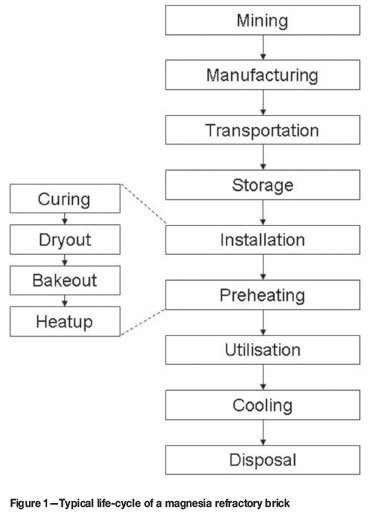
During the installation and preheating stages the brick undergoes several changes20. Curing is the formation of hydraulic bonds. Curing follows the placement of the material and is limited to wet installations of magnesia refractory bricks. In wet installations, mortar is utilized as a bonding agent between the bricks. The hydraulic bond forms at ambient temperature within 24 hours of placement i.e. during installation. Dryout is the removal of moisture to render the lining safe to start the process at a later stage. Bakeout is the formation of chemical bonds at elevated temperatures. Heatup is the continuation of the dryout or bakeout stages to the point where the furnace can be put into operation.
Literature perspective: dryout process
The preheating of the refractory is based on a preheating curve prescribed by the refractory manufacturer9,16, who calculate a rate based on a set of laboratory tests and knowledge of the stresses and strains caused in the refractory material by the preheating process2. During dryout some of the moisture contained in the refractory bricks evaporates from the hot face-combining with other furnace off-gases- but most of the moisture moves from the hot face to the cold face, eventually condensing against the cold steel shell and draining from the bottom of the furnace shell16,20.
Figure 2 summarizes the inputs, process steps, outputs, and equipment involved in a dryout process where measures are put in place to prevent magnesia refractory from hydration by moisture condensing from the off-gas and by moisture condensing against the furnace shell.
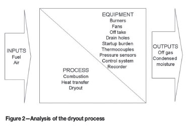
Portable high velocity burners are utilized extensively for refractory dryout in pyrometallurgical smelters4,10 and in glass melting furnaces9,19. In the burners, fuel is combusted in air supplied by fans attached to the burners9. Off-gas containing products from the combustion and dryout processes vent through an offtake and condensed moisture from the dryout process drains through drain holes in the bottom of the furnace shell14,20. The offtake is installed at the highest position in the furnace19 and is initially operated without any water cooling, especially when the off-gas contains moisture originating from combustion products, air with high humidity, and the refractory material being dried10.
Fuels utilized in portable high velocity burners include wood, coal, char16, Sasol gas10, natural gas, and oil7. Gas is preferred16because:
Burners are operated with air to fuel ratios much higher than what is required for stoichiometric combustion of the fuel. The excess air is utilized in a forced convection heat transfer process where the scrubbing action of the hot, dry air transfers heat to the refractory lining9.
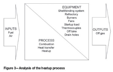
The layout and placement of the burners and fans are designed in such a manner that the heat transferred from the hot, dry air to the refractory material is homogenous9. If start-up burden is installed prior to preheating, its layout is designed to ensure homogenous heat transfer from the hot, dry air to the refractory lining, but the burden is preferably introduced when the heatup process reached operating temperatures5 (Figure 3).
Furnace pressure sensors monitor the pressure inside the furnace during preheating. The furnace pressure is kept constant, positive, and high enough to ensure that the hot, dry air reaches all of the refractory lining and that the off-gas vents from the furnace. The furnace pressure is measured with pressure sensors installed in the furnace roof and controlled through changing the position of a damper in the off-gas vent9.
Thermocouples are utilized in various applications during preheating of the refractory lining:
Measurements taken by furnace pressure sensors and permanent thermocouples are logged through the plant control system and databases, and measurements taken by expendable thermocouples are recorded with a portable recorder.
Case study
In the following case study, hydration of an installed magnesia furnace lining delayed furnace commissioning by three months despite the implementation of several of the preventative measures described in the preceding paragraphs.
In the period preceding the commissioning of a 36 MW DC furnace lined with magnesia bricks, excessive precautions were taken during refractory installation to mitigate the risk of hydration. These included storing the refractories in a dry area, removing the refractory pallet wrapping only as the bricks were needed, erecting a tarpaulin immediately above the furnace roof to serve as a barrier between the installed refractory lining and cooling water piping above it, and allowing no water on the immediate levels around the furnace tapholes and roof. Actual dryout of the bricks was already conducted at the manufacturing site of the refractory supplier; moisture removal from the bricks was therefore not required. Also, being a dry installation, no wet mortar was used.
During December 2002, preheating (heatup) of the furnace commenced. The two primary objectives of the preheating stage were:
Limiting the temperature gradient between the hot and cold faces of the refractory brick.
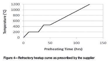
During the preheating stage the refractory brick hot face was in contact with the hot gases, while the cold face was in contact with a thermally conductive carbon paste, which filled the gap between the brick and water cooled furnace shell. This creates a thermal gradient along the longitudinal axis of the brick and, since magnesia undergoes thermal expansion, mechanical stresses are induced: more so at the hot face than at the cold face. When excessive, these stresses will lead to cracking of the brick. A slow heatup curve, as prescribed by the refractory supplier and designer, and illustrated in Figure 4 was therefore followed. Thermocouples hanging from the roof into the furnace internal volume and measuring the internal gas temperature were used as reference temperature. The underlying assumption was that the internal gas temperature is equal to that of the refractory hot face.
Reaching 800ºC on the hot face of the hearth bricks before internal temperatures are elevated to temperatures where the first liquid iron will form.
According to the refractory installation design of the given furnace, the spacing provision between the installed bricks would be completely closed when the bricks reached 800ºC. Reaching this condition before liquid iron is brought into contact with the hearth would prevent iron penetration into the hearth. However, heat transfer to the hearth hot face was hampered by the presence of a 150 mm thick sacrificial lining, and an initial iron burden of several hundreds of tons. Both sacrificial lining and initial burden covered the full area of the hearth. To overcome this constraint, two holding periods were included in the preheat curve (Figure 4), thus giving the refractory lining soaking time and the hearth time to catch up with the refractory walls.
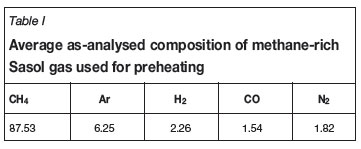
Methane-rich Sasol gas with an average composition as shown in Table I was used for preheating. The Sasol gas was combusted with excess air at ambient temperature and humidity. The combusted gas and heated air were vented from the furnace via the off-gas duct. Being designed to handle high temperature off-gases during operational conditions, the duct had forced water cooling coils running along its external surface and covering its full length.
During the preheating stage of commissioning, the following constraints which were often opposing, required management by the commissioning team:
Approximately 36 hours after commencing with the preheat, the process was halted due to excessive water damage to the magnesia refractories. The water originated from the humid air utilized for combustion and its subsequent condensation within the water cooled duct (the contribution from the combustion products of the Sasol gas was, in this instance, negligible).
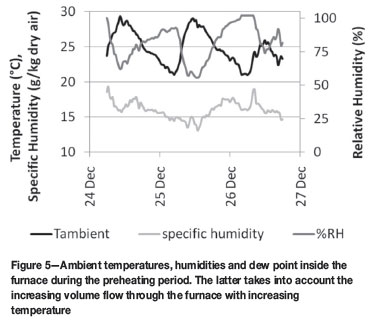
Humidity and temperature readings for the days over which preheating were conducted are given in Figure 5. Temperatures ranged in the high twenties, while humidities were close or equal to 100% over the period. This combination results in a humidity load to the internal furnace above 15 g/kg dry air over the last few hours of the hold at 200ºC and the subsequent initial increase in internal furnace temperature. At the typical air consumption rates of 10 000-12 000 m3/h, this results in 170 200 kg of water per hour. While present as vapour within the heated furnace volume, a major part of this water condensated along the inside of the water-cooled off-gas duct, which was kept cool for the reasons as given above.
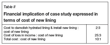
The cost of unsuccessful risk identification in the instance of the case study was not only replacement of the complete refractory lining, but also the consequential loss in production. Relining the furnace took three months-one month to demolish the hydrated lining, and produce and deliver the new lining; one month to install the new lining, and one month for preheating. Although the actual financial figures are proprietary, the financial implications of the incident can be expressed in terms of the cost of the new lining as indicated in Table II.
Preventing refractory hydration: a management perspective
In the case study described above, hydration of magnesia refractories was a known risk. Despite this, it still occurred. It was therefore not failure of recognising the risk, but a failure of recognizing all the sources of the risk and balancing the probabilities of the multitude of risks typical of a commissioning process. Based on the experience of management measures, which worked well, as well as lessons learned during the case study, the following are listed as key factors in enabling risk and risk source identification and recognition within a commissioning environment:
Conclusion
Although companies in Southern Africa commercially produce nineteen types of commodities at more than sixty smelters25 very little literature is available on furnace start-up on any type of lining. As furnace start-up events are not something that occurs on a regular basis in continuous smelting operations, sharing experiences, and more importantly the lessons learned from these experiences, would allow for constructive debate on best practices in furnace dryout and heatup. Keeping in mind the significant costs involved in a failed start-up, best practices in furnace start-up is something the pyrometallurgical industry could benefit from significantly.
References
1. AGARWAL, J.C. and KATRAK, F.E. Economic impact of startup experiences of smelters. Advances in Sulphide Smelting: Proceedings of the 1983 International Sulphide Smelting Symposium and the 1983 Extractive and Process Metallurgy Meeting, vol. 2, 1983, pp. 1129-1140. [ Links ]
2. AINSWORTH, J.H. Calculation of safe heat-up rates for steelplant furnace linings. Ceramic Bulletin, vol. 58, no. 7, pp. 676-678. [ Links ]
3. BUHR, A. Refractories for steel secondary metallurgy. CN-refractories, vol. 6, no. 3, 1979, 1999, pp. 19-30. [ Links ]
4. DONALDSON, K.M. et al. Design of refractories and bindings for modern high-productivity pyrometallurgical furnaces. Proceedings of the International Symposium on Non-ferrous Pyrometallurgy-Trace Metals, Furnace Practices and Energy Efficiency, 1992, pp. 491-504. [ Links ]
5. GLASTYAN, G.A. High-speed heat-up of open-hearth furnaces after cold repairs. Metallurgy, no. 5, May 1966, pp. 22-23. [ Links ]
6. GARBERS-CRAIG, AM. How cool are refractory materials? Journal of the Southern African Institute of Mining and Metallurgy, vol. 108, no. 9, September 2008, pp. 491-506. [ Links ]
7. KIRKHAM, A.D. Heat up of furnaces old and new. Glass Technology, vol. 26, no. 6, 6 December 1985, pp. 258-260. [ Links ]
8. KIRK-OTHMER. Encyclopedia of Chemical Technology, 5th edition, vol. 15, 2005, p. 221-228. [ Links ]
9. KOPSER, G. Furnace heat-up techniques adapt to melter design. 1991. [ Links ]
10. KOTZE, H. et al. Ilmenite smelting at Ticor SA. Journal of the Southern African Institute of Mining and Metallurgy, vol. 106, March 2006, pp. 165-170. [ Links ]
11. LANSER, VON P. and SKALLA, N. Hydratationsbeständige magnesitsteine. Radex-Rundschaft, vol. 41, no. 6, 1953. [ Links ]
12. LAUZON, P., RIGBY, J., OPREA, C., TROCZYNSKI, T., and OPREA, G. Hydration Studies on Magnesia-Containing Refractories, Uniterr, 2003, pp. 51-63. [ Links ]
13. LAYDEN, G.K. and BRINDLEY, G.W. Kinetics of vapor-phase phase hydration of magnesium oxide. Journal of the American Ceramics Society, vol. 46, no. 11, 1963, pp. 518-522. [ Links ]
14. LI, Y. and ARHTUR, P. Yunnan Copper Corporation's new smelter-China's first Isasmelt. Yazawa International Symposium, Metallurgical and Materials processing: principles and technologies, vol II: high-temperature metals production, 2003, pp. 371-384. [ Links ]
15. MCCLELLAND, R. et al. Commissioning of the Ausmelt lead smelter at Hindustan Zinc. TMS Fall Extraction and Processing Division: Sohn International Symposium, no. 8, 2006, pp. 163-171. [ Links ]
16. RHI REFRACTORIES. Refractory Bricks in Rotary Kilns, Installation Guide, RHI Refractories, England. 2003. [ Links ]
17. SAXENA, J.P. Refractory Engineering and Kiln Maintenance in Cement Plants, Taylor and Francis Group, United Kingdom, 2003, pp. 166-168. [ Links ]
18. SEVERIN, N.W. Dryouts and heatups of refractory monoliths. Advances in Ceramics, vol. 13, 1985, pp. 192-198. [ Links ]
19. SEVERIN, N.W. Controlled-temperature dryouts of refractory linings. Ceramic Engineering and Science Proceedings, vol. 16, no. 1, 1995, pp. 199-202. [ Links ]
20. SEVERIN, N.W. Refractory dryout-how can we improve it? Canadian Ceramics, February 1998, pp. 21-23. [ Links ]
21. VERSCHEURE, K., KYLLO, A.K., FILZWIESER, A., BLANPAIN, B., and WOLLANTS, P. Furnace Cooling Technology in Pyrometallurgical Processes, The Minerals, Metals and Materials Society, 2006. [ Links ]
22. WALLNER, S., FILZWIESER, A., and KEICKER, J. Some aspects for the use of water cooled furnace walls-Water the best refractory?, RHI AG Vienna, Vienna Austria. 2009 [ Links ]
23. www.pyrometallurgy.co.za accessed on 18 March 2009. [ Links ]
24. ZHOU, A., TROCZYNSKI, T., OPREA, G., RIGBY, J., and LAUZON, P. Hydration kinetics of magnesia-based bricks, American Ceramic Society, Canada. 2006. [ Links ]
25. www.pyrometallurgy.co.za. [ Links ]
Paper received Aug. 2010; revised paper received Mar. 2011.
© The Southern African Institute of Mining and Metallurgy, 2011. SA ISSN 0038-223X/3.00 + 0.00.

