


Servicios Personalizados
Articulo
 Inglés (pdf)
 Articulo en XML
 Referencias del artículo
Indicadores

Links relacionados
-
 Citado por Google
 -
 Similares en Google
Compartir

 Permalink
South African Journal of Industrial Engineering
versión On-line ISSN 2224-7890
versión impresa ISSN 1012-277X
S. Afr. J. Ind. Eng. vol.34 no.4 Pretoria dic. 2024
http://dx.doi.org/10.7166/34-4-2982
GENERAL ARTICLES
Implementation of a digital twinning approach to improve designs of polyurethane heart valves
L. MasheaneI, ; W. du PreezII; J. CombrinckI
IDepartment of Mechanical and Mechatronics Engineering, Central University of Technology, Bloemfontein, South Africa
IICentre for Rapid Prototyping and Manufacturing, Faculty of Engineering, Built Environment and Information Technology, Central University of Technology, Bloemfontein, South Africa
ABSTRACT
Young sub-Saharan African and developing-world patients with rheumatic heart valve diseases urgently require cost-effective prosthetic valves. To design cost-effective polyurethane heart valves, comprehend haemodynamic behaviour, expedite prototype development, and reduce the need for clinical testing for functional evaluation, the implementation of an experimental test digital twinning is essential. The use of computational fluid dynamics (CFD) and finite element analysis (FEA) to improve heart valve replacement designs rapidly, in order to comply with the minimum requirements of Food and Drug Administration (FDA) and International Organization for Standardization (ISO) regulations and specifications, forms the core of this study. This approach is presented, and the results are discussed. A conclusion is drawn about the valve geometric orifice area (GOA) compared with experimental tests. When the valve was fully opened, there was only an 11% difference between the computed experimental and the finite element GOA. Digital simulation revealed additional information such as the locations of stress concentrations. The FE results showed reasonable similarity with in vitro results.
OPSOMMING
Jong pasiënte in sub-Sahara Afrika en die ontwikkelende wêreld met rumatiese hartklepsiektes benodig dringend bekostigbare prostetiese kleppe. Om bekostigbare poliuretaan-hartkleppe te ontwerp, hemodinamiese gedrag te begryp, prototipe-ontwikkeling te bespoedig en die behoefte aan kliniese toetsing vir funksionele evaluering te beperk, is die implementering van 'n digitale tweeling van eksperimentele toetsing noodsaaklik. Die gebruik van berekeningsvloeistofdinamika (CFD) en eindige-elementanalise (FEA) om hartklepvervangingsontwerpe vinnig te verbeter, ten einde te voldoen aan die minimum vereistes van FDA en ISO regulasies en spesifikasies, vorm die kern van hierdie studie. Hierdie benadering word aangebied, en die resultate word bespreek. 'n Gevolgtrekking word gemaak oor die klep se geometriese opening area (GOA) in vergelyking met eksperimentele toetse. Met die klep heeltemal oop, was daar slegs 'n 11% verskil tussen die berekende eksperimentele en die eindige element GOA. Digitale simulasie het bykomende inligting aan die lig gebring, soos die liggings van spanningskonsentrasies. Die eindige element resultate het redelike ooreenkomste met die in vitro resultate getoon.
1. INTRODUCTION
1.1. The need
The challenge in sub-Saharan Africa and the developing world is to develop a cost-effective prosthetic valve for the young (<65-year-old) rheumatic heart valve disease population of 33 million [1]. There have been many attempts to design and manufacture cardiac valves that can function as effectively and reliably as native valves [1]-[4]. Decades of research and development have shown that this is an extremely difficult task [5]. Researchers are focusing on understanding the structural mechanics of bioprosthetic heart valves and the longevity of mechanical heart valves in order to improve polymeric heart valves [6][7].
The geometry of the leaflet directly affects the durability and haemodynamic performance of a valve, while synthetic material offers the potential to control physical, mechanical, and chemical properties to an extent not possible with biological material [8]. Although it is generally accepted that the geometry of a polymer valve should match the natural valve geometry as closely as possible, this is not easily achieved.
1.2. Previous work
Designing an artificial heart valve is a complex and time-consuming process, in which the minimum requirements of Food and Drug Administration (FDA) and International Organization for Standardization (ISO) regulations and specifications must be met before clinical trials can begin. A previous study by the authors revealed that the snap-through of the leaflets was not only affected by the leaflets' thickness, but also by the curvature of the geometry [5]. For a valve to open with ease, care should be taken to moderate the rigidity of the leaflet and to minimise the total regurgitation of a valve. For this, a moderate elasticity is required. Several studies have confirmed the abovementioned outcomes while describing the design of polymer valves and their failures [9]-[11]. In-depth research into and comprehension of the polyurethane valve's hydrodynamic behaviour is required to review the leaflet design geometry of the valve.
The hydrodynamic evaluation of heart valves conducted under dynamic conditions in a controlled environment is required during the design phase in order to predict their haemodynamic behaviour prior to clinical trials. However, many researchers have reported that the in vitro test results were not identical to the in vivo performance of the valve [9]. The contracting phase of the cardiac cycles is known as systole, when blood is pumped from the ventricles into the pulmonary artery and aorta. The resting phase of the cardiac cycle is known as the diastole, during which the heart muscle relaxes and blood can flow from the atriums into the ventricles. Prototype heart valves are put through tests in a pulse duplicator to gather precise information on how they function. The pulse duplicator offers ways to artificially mimic how a human heart functions in order to evaluate prototype heart valves.
The ideal heart valve should satisfy the minimal pressure and flow measurements that are regarded as the primary determinants of valve performance, and should be evaluated with respect to the following parameters: stroke volume, regurgitation, cardiac output, and mean systolic pressure difference [12].
A pulse duplicator system provides values for
1. average pressure drop
2. effective orifice area (EOA)
3. closing volume
4. leakage volume, and
5. total regurgitation
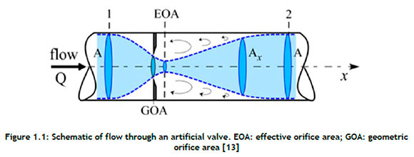
Figure 1.1is used to explain the relevant terminology and parameters. The effective orifice area, also known as the area of flow at the vena contracta (the vertical dotted line in Figure 1.1 where Q is the flow rate, EOA is the effective orifice area, GOA is the geometric orifice area, A is the cross-sectional area of the tube, and Ax is the instantaneous area of the flow), is a typical metric that evaluates valve function by quantifying valve stenosis [13]. It evaluates a heart valve's capacity to permit fluid to pass through the orifice during the cardiac cycle's valve opening phase. The Gorlin relation, given here as Equation 1, was used to calculate the EOA [13][14]:
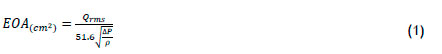
where Qrms is the root mean square aortic valve flow rate (cm3/s), 51.6 is a constant derived from the Bernoulli equation, ΔP is the mean pressure drop (mmHg) over the full cardiac cycle, and ρ is the mass density (gcm-3) of the fluid.
A cardiac valve's ability to enable blood to flow through it is determined by the average pressure drop across the valve. Multiple in vitro studies have focused on identifying methods to determine the EOA accurately while the valve is opening. However, recent studies have shown that the direct measurement of the EOA does not reflect the area formed by the free edges of aortic valve leaflets, known as the geometric orifice area (GOA) [11], [14]-[17]. These findings suggest that the EOA obtained from pulse duplicator data would have to be converted to the GOA to provide a clear indication of the displacement of leaflets while open. Based on empirical constants obtained from the pulmonary valve, an original mathematical formulation that relates the AP and flow rate (Q) to the GOA was derived [14], [16], and is given by Equation 2.

This was suggested as an effective way to predict the GOA for the aortic valve as well [14]-[16]. 'Regurgitation' is defined as the reverse flow of blood through the heart valve. The quantification of regurgitation is measured in two different volumes, the closing volume and the leakage volume.
1.3. Digital twinning, the next phase
The application of a computerised simulation of an experimental test (pulse duplicator digital twinning) approach can accelerate the prototype development of cost-effective prosthetic valves for young sub-Saharan African and global developing-country patients with rheumatic heart valve disease. With this implementation, it would be possible to analyse rapidly the stresses and displacements present in the leaflets. In this study, a framework for integrating computational fluid dynamics (CFD) and finite element analysis (FEA) into the design process was created to minimise protracted experimental tests, including pulse duplication, and to reduce the cost of development.
A commercially available Carpentier-Edwards Perimount Magna 19 mm valve was compared with two polycarbonate urethane tri-leaflet heart valves. By contrasting the data from experimental tests with commonly used dynamic characteristics such as pressure drop and EOA, the CFD model was evaluated and validated. Furthermore, this digital twinning strategy gave rise to a more thorough comprehension of the functioning of the aortic valve and the underlying physics of its substitutes.
2. MATERIAL AND METHODS
2.1. Design of the tri-leaflets
The commercially available biological (Carpentier-Edwards Perimount Magna 19 mm) valve shown in Figure 2.1(a) was reverse-engineered to obtain the baseline geometry. The valve typically comprises three thin leaflets attached to a cylindrical support frame (see Figure 2.1(b)), referred to as the stent, which incorporates a sewing ring. The stent has three posts to support flexible leaflets. The sewing ring has three arch saddles to ensure conformity with the aortic annulus.
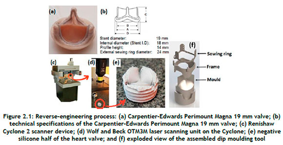
The Carpentier-Edwards Perimount Magna 19 mm valve was fixed in a sewing cuff, and silicone was cast on to both sides of the valve and allowed to cure, as shown in Figure 2.1(e). The two negative silicone halves were laser-scanned using a Renishaw® Cyclone 2 coordinate measuring machine (Figure 2.1(c)). Scan data was obtained with a Wolf & Beck OTM3M optical laser scanner (shown in Figure 2.1(d)) at a scanning rate of up to 400 points per second with a resolution of 5 µm. A point cloud obtained from the scanned data was converted to a standard triangle language (STL) file using Trace Scan 24A software. The resultant mesh was cleaned up, smoothed, and sculpted to the required shape with the use of Geomagic® Quality software. The final non-uniform rational Bézier spline (NURBS) file was exported to CAD software to generate a solid model of the valve. A mould for the dip moulding process was created from the CAD data (see Figure 2.1(f)).
Figure 2.2shows the three-dimensional geometries that were generated using SolidWorks (Dassault Systèmes SolidWorks Corp., Waltham, MA). The complex geometry of the leaflets is revealed, with different curvatures in the circumferential direction (i.e., parallel to the leaflet's free edge), and radial direction (i.e., perpendicular to the circumferential direction).
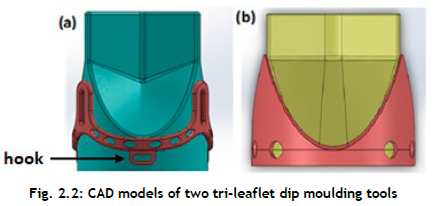
A CAD model of the tri-leaflet dip moulding tool (Figure 2.2 consists of the stent with three posts to which the three PCU leaflets are attached, with an exterior diameter of 19 mm. The frame part was designed in such a way as to lock the sewing ring into three hooks. This design feature was implemented to locate the stent correctly and to fix it to the mould assembly.
2.2. Materials and fabrication techniques
The leaflets in a prosthetic valve must survive a demanding in vivo environment, with highly dynamic loading, high strain rates, and anisotropic stretching. Therefore, the mechanical properties of the leaflet material are of fundamental importance in ensuring not only valve competence but also long-term durability. Polycarbonate urethane has been proven by many researchers to have suitable mechanical strength, flexibility, and durability for use in tri-leaflet polymer heart valves [10], [18], [19]. To manufacture a dip-moulded polymer heart valve, a solution of commercial trademark polycarbonate urethane (PC3595A clear) supplied by the Lubrizol Europe Coordination Centre, which is part of the Lubrizol Life Science Group, was dissolved in an N, N-dimethylacetamide (DMAc) solvent. The viscosity of the solution depends on the solid content, which can be altered by adding more solvent or polycarbonate urethane material to the solution until the desired consistency is obtained [5].
The valve frame to which the polyurethane leaflets are attached and the mould were prepared through a direct metal laser sintering (DMLS) process. For the stent, titanium alloy (Ti6Al4V) was selected owing to its high strength and fatigue resistance. Polycarbonate urethane valves with an internal diameter of 19 mm were produced through dip moulding. The dip-moulding process produces a part with internal dimensions and shapes that are identical to the external dimensions of the mould. Because there is no shrinkage during the process, extremely accurate internal dimensions are produced with free-flow dimensions on the exterior surface.
An Edwards Lifescience 19 mm perimount aortic valve (see Figure 2.3(a)) was compared with two custom-designed and dip-moulded 19 mm polycarbonate urethane heart valves. The PCU valve, referred to as 'PCU tall' (Figure 4(b)), is the initial polycarbonate urethane tri-leaflet heart valve. Its post height is 8,9 mm. The second custom-designed valve, PCU short (Figure 4(c)), consists of a 5,2 mm post height and a different shape from that of the initial design.
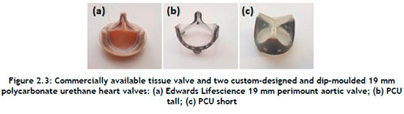
The tissue heart valve provided baseline values for comparison, as the valve is in commercial use and has been proven to have adequate haemodynamic performance and fatigue resistance. If the PCU valve could meet or exceed the performance of the biological valve currently on the market, then there would be no reason not to approve its use in humans.
2.3. In vitro assessment
A ViVitro CPD (ViVitro Labs Inc., British Columbia, Canada) system, combined with the ViVitest data acquisition system, was used for pulse duplication at the Robert WM Frater Cardiovascular Research Centre at the University of the Free State in Bloemfontein, South Africa. A comparison of the various regions of a heart with the ViVitro CPD is shown in Figure 2.4
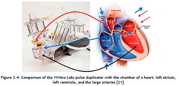
The system consisted of a tank to serve as a reservoir, a volumetric pumping system to operate as a heart, and a valve housing unit designed according to the guidelines of the ISO 5840 standard. The pressure ports and flow measuring locations allowed for data collection from the aortic or mitral sites. The ViVitest software controlled the system while simultaneously collecting and analysing physiological flow and pressure data.
The simulated systemic circulatory loop was filled with a saline-glycerol combination consisting of 47.3% saline and 52.7% distilled water to achieve a density and viscosity similar to that of blood. As shown in Table 2.1 each valve was examined under the same operating circumstances. Under aortic valve conditions, the pressure was set between 120 mmHg and 80 mmHg.
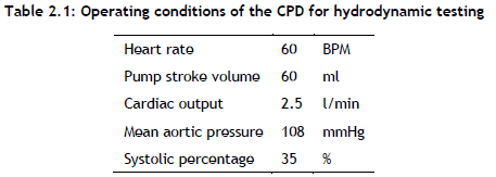
The transvalvular pressure drop was measured at a constant frequency of 60 bpm and 60 millilitre stroke volume.
2.4. Computational study
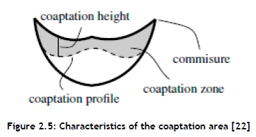
Optimising the design to reduce the operational stress would minimise the incidence of restenosis and ultimately increase the heart valve's life span. Therefore, to improve the leakage volume and total regurgitation, a study of the coaptation area (see Figure 2.5 was necessary. With a similar approach, certain parameters such as leaflet height, curvature, and commissure shape might be determined.
A computational model was built to reproduce the experimental testing by using Simcenter STAR-CCM+ software. A single solid physics continuum was used that contained the necessary models for computing solid stress on an isotropic hyperelastic polymer using the neo-Hookean hyperelastic material laws [23]. The stent frame had a diameter of 19 mm, with the leaflets being 100 µm thick. A small gap between the leaflets was enforced with an applied three Hex 8 elements mesh setup over the thickness of the leaflet using a directed mesh operation. The operational stress and the displacement of the leaflets were computed for one cycle.
3. RESULTS AND DISCUSSION
3.1. Experimental analysis
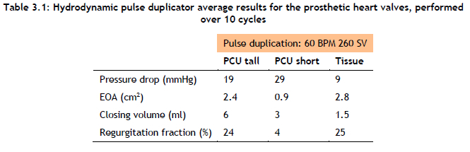
The programmable waveform generator of the pulse duplicator was used to set the stroke volume (SV) and beats per minute (BPM), as shown in Table 3.1 When the flow conditions reached a steady state at the specified testing flow condition, 10 cycles were captured.
A detailed pressure drop across the valves over a period of 10 cycles is displayed in Figure 3.1(a). These results displayed meaningful trends for a comparison of the different valves. The pressure drop for the PCU short valve was significantly larger than those for the PCU tall and tissue valves under aortic valve conditions. This was because the PCU short valve leaflets were designed so that they were affixed to the stent, and this made a significant difference compared with the PCU tall valve. The PCU tall valve leaflets extend vertically off the stent before bending towards the valve centre, in contrast to the PCU short valve leaflets, which protrude radially towards the centre of the valve. As a result, the PCU tall valve can open more quickly than the PCU short valve, resulting in an increased open geometric area (Figure 3.1(b) and decreased pressure drop (Figure 3.1(a)).
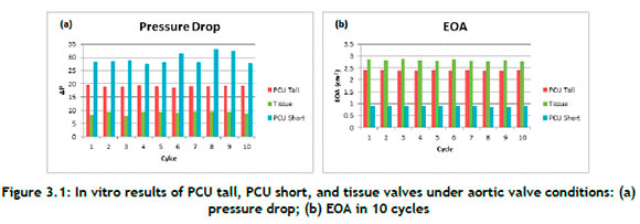
The EOA provides a measure of how easily fluid can pass through the heart valve. Figure 3.1(b) displays the EOA of the three cardiac valves that were evaluated while the aortic valve was open. The EOA of the tissue valve was the largest of the three valves. However, the EOA of the PCU tall valve was slightly less when compared with the EOA of the tissue valve, with an average difference of 14.9%. The PCU short valve had the lowest of all of the EOA values, with an average of 0.9 cm2.
The GOA of the PCU short valve was found to be much less than that of the PCU tall valve by measuring the opening of the heart valves at peak systole, as shown in Figure 3.2 The PCU short valve had an orifice diameter of about 12 mm, whereas the PCU tall valve had an orifice diameter of about 18 mm.
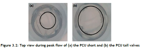
Figure 3.3(a) shows the PCU tall, PCU short, and tissue valve closing volumes. In comparison with the PCU tall valve and the PCU short valve, the tissue valve had the lowest closing volume. This also demonstrates how the PCU tall valve snap-through made it more difficult to close the valve and increased the closing volume.
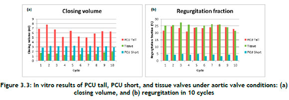
The percentage regurgitation across valves is shown in Figure 3.3(b). The tissue valve displaced to close quickly and efficiently, with an average of 25%. While the PCU tall valve showed similar characteristics, because of the snap-through effect seen in the pulse duplicator machine, the valve took a little longer to close, which significantly increased the closing volume.
The in vitro tests revealed that the PCU tall valve outperformed the PCU short valve in respect of pressure drop, EOA, leakage volume, and regurgitation fraction. Given this information, the rest of the paper deals with the analysis of the performance of the PCU tall valve in a complete cardiac cycle through finite element (FE) numerical simulation.
3.2. Finite element numerical simulation compared with experimental data
The in vitro pulse duplicator results and the FE simulation results were quantitively compared in order to assess the reliability of the FE simulation and to determine the impact of the critical parameters on the function of a PCU tall valve.
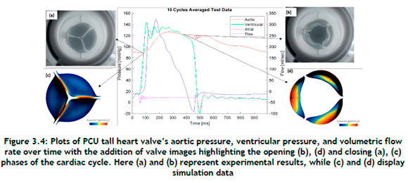
Figure 3.4displays the aortic pressure, ventricular pressure, and volumetric flow rate averaged over ten cardiac cycles under aortic circumstances for PCU tall valves. Time = 0 s depicts the start of the systole and the beginning of the cardiac cycle. The peak aortic pressure reaches a level of about 120 mmHg and then gradually falls to about 80 mmHg. Two parameters, namely the GOA and the maximum von Mises stress, were chosen to compare and evaluate the performance of the modelled PCU tall valve. GOA is a simple characteristic to measure, and its maximum value provides a more accurate assessment of the functioning of valves. Increased leaflet stresses are correlated with calcific degeneration; thus knowledge of the stress distribution helps to determine the longevity of the PCU tall valve.
3.2.1. Evaluation of geometric orifice area
The GOA was evaluated by comparing the images from the in vitro test with the images from the numerical simulation. For this, the total deformation contour plots at t = 380 ms were used to determine the GOA from the FE model results when the valve was fully open. Figure 3.4(d) shows the GOA simulation results with the computed maximum value of 285 mm2, which was found to be the maximum for the PCU tall valve. At the maximum opening of the valve, the in vitro test and the FE analysis were shown to have a GOA discrepancy of 11%. Furthermore, the simulation-generated shape of the closed valve closely resembled that of the experimental one.
3.3. Stress field on the valve
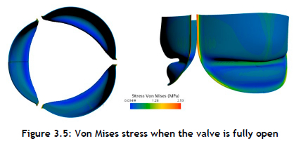
Data for the Von Mises stress for elements positioned at the belly of the PCU tall valve, near commissures, and at the leaflets' free edges were acquired for a more detailed kinematic study. The Von Mises stress field from the numerical simulation is shown in Figure 3.5 The operating range of the Von Mises stress during the opening phase of the leaflets was observed to be 0.03 - 2.53 MPa. This stress distribution clearly reflects a high risk of calcium build-up by causing structural disintegration. When the valve was at its maximum systole, the areas with the largest stress concentrations were found close to the commissures. In addition, it was discovered that the coaptation area of the valve had a significantly higher stress distribution than the belly region.
A nonlinear finite element model was used by Korman and Vander to predict the stress distribution on the leaflets while using a more accurate geometry for the aortic valve [24]. In comparison with the simplified shape used by Gould et al. [25], their findings indicated that the magnitude of the stresses would be higher with a native valve geometry. Furthermore, Thubrikar et al. demonstrated that the design characteristics of the valve vary continually over a cardiac cycle, and that any departure from the natural valve design would jeopardise the prosthetic valve's ability to operate effectively [25].
This paper's purpose was not to investigate thoroughly the kinematic study of the valve, but rather to demonstrate how FE simulations may mimic the experimental test while producing reasonable results. The outcomes of the FE simulation, however, encourage additional research to examine the leaflet life span in greater detail, such as the valve fatigue test to describe the Von Mises stress range specifically for the material used to manufacture this valve.
It is suggested that, with the revised design, more flexible commissures may play a significant role in the opening phase by not over-stretching the leaflets and, during diastole, by enabling a twist and a modest ventricular prolapse of the leaflets to minimise possible leakage of the valve.
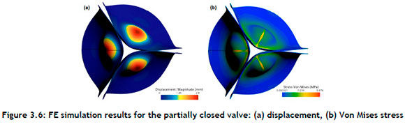
Figure 3.6shows that the coaptation of the leaflets was a factor in determining the closing volume, because the closing volume is the backflow while the valve is changing from an open position to a closed position. An optimised design should address the snap-through characteristics observed on the leaflets.
4. CONCLUSION
The application of pulse duplicator digital twinning enabled a rapid evaluation of the valve's functionality and a determination of the degree of its efficacy in specified environments at a minimal cost. The outcomes demonstrated that the developed model could predict the opening and closing of the valve with an 11% difference compared with the experimental data when the valve was open. Furthermore, the model displayed the areas with high tensile and bending stress formation, which, when they exceed the critical values, could accelerate leaflet structural fatigue degradation. In addition, at the commissures, stress concentration in the leaflets was more pronounced, and could contribute to the initiation of calcification by causing structural disintegration. Digital twinning has emerged as a useful tool in the design process of the polymer valve. A fluid-structure interaction model will have to be developed to investigate fluid behaviour and stent behaviour and how they interact with each other.
REFERENCES
[1] C. M. Mvondo, M. Pugliese, A. Giamberti, D. Chelo, L. M. Kuate, J. Boombhi, and E. M. Dailor, Surgery for rheumatic mitral valve disease in sub-Saharan African countries: Why valve repair is still the best surgical option, Pan African Medical Journal, 24, 307, 2016. doi: 10.11604/pamj .2016.24.307.7504 [ Links ]
[2] H. Ghanbari, H. Viatge, A. G. Kidane, G. Burriesci, M. Tavakoli, and A. M. Seifalian, Polymeric heart valves: New materials, emerging hopes, Trends in Biotechnology, 27(6), 359-367, 2009. doi: 10.1016/j.tibtech.2009.03.002 [ Links ]
[3] G. D. Baura, Heart valves, In G. D. Baura, Medical device technologies: A systems based overview using engineering standards, Amsterdam, Netherlands: Elsevier, 2012, 121-145. doi: 10.1016/B978-0-12-374976-5.00006-2 [ Links ]
[4] M. Kütting, J. Roggenkamp, U. Urban, T. Schmitz-Rode, and U. Steinseifer, Polyurethane heart valves: Past, present and future, Expert Review of Medical Devices, 8(2), 227-233, 2011. doi: 10.1586/erd.10.79 [ Links ]
[5] L. Masheane, W. du Preez, and J. Combrinck, Assessment of manufacturability and performance of polyurethane heart valves produced through a locally developed dip moulding process, In Proceedings of 17th RAPDASA Annual International Conference, 2016, 4(2), pp. 5-37. [ Links ]
[6] U. Gulbulak, O. Gecgel, and A. Ertas, A deep learning application to approximate the geometric orifice and coaptation areas of the polymeric heart valves under time - varying transvalvular pressure, Journal of the Mechanical Behavior of Biomedical Materials, 117, 104371, 2021. doi: 10.1016/j.jmbbm.2021.104371 [ Links ]
[7] F. Guo, K. Jiao, Y. Bai, J. Guo, Q. Chen, R. Yang, and X. Zhang, Novel transcatheter aortic heart valves exhibiting excellent hemodynamic performance and low-fouling property, Journal of Materials Science & Technology, 35(1), 207-215, 2019. doi: 10.1016/j.jmst.2018.09.026 [ Links ]
[8] R. L. Li, J. Russ, C. Paschalides, G. Ferrari, H. Waisman, J. W. Kysar, and D. Kalfa, Mechanical considerations for polymeric heart valve development: Biomechanics, materials, design and manufacturing, Biomaterials, 225, 119493, 2019. doi: 10.1016/j.biomaterials.2019.119493 [ Links ]
[9] B. Rahmani, S. Tzamtzis, H. Ghanbari, G. Burriesci, and A. M. Seifalian, Manufacturing and hydrodynamic assessment of a novel aortic valve made of a new nanocomposite polymer, Journal of Biomechanics, 45(7), 1205-1211, 2012. doi: 10.1016/j.jbiomech.2012.01.046 [ Links ]
[10] F. Oveissi, S. Naficy, A. Lee, D. S. Winlaw, and F. Dehghani, Materials and manufacturing perspectives in engineering heart valves: A review, Materials Today Bio, 5, 100038, 2020. doi: 10.1016/j.mtbio.2019.100038 [ Links ]
[11] X. Shen, L. Bai, L. Cai, and X. Cao, A geometric model for the human pulmonary valve in its fully open case, PLoS One, 13(6), e0199390, 2018. doi: 10.1371/journal.pone.0199390 [ Links ]
[12] J. R. Stasiak et al., Design, development, testing at ISO standards and in vivo feasibility study of a novel polymeric heart valve prosthesis, Biomaterials Science, 8(16), 4467-4480, Aug. 2020. doi: 10.1039/d0bm00412j [ Links ]
[13] F. M. Susin, Complete unsteady one-dimensional model of the net aortic pressure drop, The Open Biomedical Engineering Journal, 13(1), 83-93, 2019. doi: 10.2174/1874120701913010083 [ Links ]
[14] D. Garcia and L. Kadem, What Do You Mean by Aortic Valve Area: Geometric Orifice Area, Effective Orifice Area, or Gorlin Area?, The Journal of heart valve disease, 15(5), 601-608, Oct. 2006. [ Links ]
[15] B. Zebhi, M. Lazkani, and D. Bark, Calcific aortic stenosis - A review on acquired mechanisms of the disease and treatments, Frontiers in Cardiovascular Medicine, 8, 734175, 2021. doi: 10.3389/fcvm.2021.734175 [ Links ]
[16] N. Saikrishnan, G. Kumar, F. J. Sawaya, S. Lerakis, and A. P. Yoganathan, Accurate assessment of aortic stenosis: A review of diagnostic modalities and hemodynamics, Circulation, 129(2), 244253, 2014. doi: 10.1161/CIRCULATIONAHA.113.002310 [ Links ]
[17] J. Adda, V. Stanova, G. Habib, and R. Rieu, In vitro correlation between the effective and geometric orifice area in aortic stenosis, Journal of Cardiology, 77(4), 334-340, 2021. doi: 10.1016/j.jjcc.2020.08.003 [ Links ]
[18] G. M. Bernacca, T. G. Mackay, R. Wilkinson, and D. J. Wheatley, Calcification and fatigue failure in a polyurethane heart valve, Biomaterials, 16, 279-285, 1995. doi: 10.1016/0142-9612(95)93255-c [ Links ]
[19] W. Wang and C. Wang, Polyurethane for biomedical applications: A review of recent developments, In J. P. Davim (ed.), The design and manufacture of medical devices, Cambridge: Woodhead Publishing, 115-151, 2012. doi: https://doi.org/10.1533/9781908818188.115 [ Links ]
[20] ViVitroLabs.com, Pulse duplicator: Most cited in-vitro cardiovascular hydrodynamic testing system. [Online]. Available: https://vivitrolabs.com/wp-content/uploads/2016/02/Pulse-Duplicator-Brochure-2016-VIVI-MKT-046.pdf [Accessed: Jul. 07, 2023] [ Links ]
[21] V. Y. Salamatova et al., Numerical assessment of coaptation for auto-pericardium based aortic valve cusps, Russian Journal of Numerical Analysis and Mathematical Modelling, 34(5), 277-287, 2019. doi: 10.1515/rnam-2019-0024 [ Links ]
[22] M. Amabili, I. D. Breslavsky, and J. N. Reddy, Nonlinear higher-order shell theory for incompressible biological hyperelastic materials, Computer Methods in Applied Mechanics and Engineering, vol. 346, pp. 841-861, 2019. doi: 10.1016/j.cma.2018.09.023 [ Links ]
[23] K. B. Chandran, S.-H. Kim, and G. Han, Stress distribution on the cusps of a polyurethane trileaflet heart valve prosthesis in the closed position, Biomechanics, 24(6), pp. 385-395, 1991. [ Links ]
[24] M. J. Thubrikar, J. Aouad, and S. P. Nolan, Comparison of the in vivo and in vitro mechanical properties of aortic valve leaflets, The Journal of Thoracic and Cardiovascular Surgery, 92(1), pp. 29-36, 1986. [ Links ]
Available online 14 Dec 2023
* Corresponding author: lmasheane@cut.ac.za
ORCID® identifiers
L. Masheane: https://orcid.org/0000-0002-8200-400X
W. du Preez: https://orcid.org/0000-0001-9935-7330
J. Combrink: https://orcid.org/0000-0002-5216-036X

