


Servicios Personalizados
Articulo
 Inglés (pdf)
 Articulo en XML
 Referencias del artículo
Indicadores

Links relacionados
-
 Citado por Google
 -
 Similares en Google
Compartir

 Permalink
South African Journal of Industrial Engineering
versión On-line ISSN 2224-7890
versión impresa ISSN 1012-277X
S. Afr. J. Ind. Eng. vol.34 no.4 Pretoria dic. 2024
http://dx.doi.org/10.7166/34-4-2900
GENERAL ARTICLES
Using topology optimisation to influence the infill placement of fused deposition modelled parts
A.D. Toth; J. Padayachee
School of Engineering, University of Kwazulu-Natal, Durban, South Africa
ABSTRACT
Additive manufacturing continues to see increased growth and adoption across various industries owing to technology improvements and increasing material options. This paper presents a method to optimise the infill structure placement in fused deposition modelling parts. The method uses finite element analysis and the bi-directional evolutionary structural optimisation technique to determine the optimal placement based on stress and validated through testing 3D-printed samples. The results show that multi-infill geometry outperforms traditional rectilinear infill in loading capacity and stiffness. The paper concludes with a real-world application, using this optimisation method on a railway-related part.
OPSOMMING
Bykomende vervaardiging sien steeds groter groei en aanvaarding oor verskeie nywerhede as gevolg van tegnologieverbeterings en toenemende materiaalopsies. Hierdie artikel bied 'n metode om die invulstruktuurplasing in saamgesmelte afsettingsmodelleringsdele te optimaliseer. Die metode gebruik eindige element analise en die tweerigting evolusionêre strukturele optimeringstegniek om die optimale plasing te bepaal gebaseer op spanning en bekragtig deur die toets van 3D-gedrukte monsters. Die resultate toon dat multi-invulling geometrie beter presteer as tradisionele reglynige invulling in laaivermoë en styfheid. Die artikel word afgesluit met 'n werklike toepassing wat hierdie optimaliseringsmetode op 'n spoorwegverwante deel gebruik.
1. INTRODUCTION
In recent years, additive manufacturing (AM) technologies have rapidly evolved in various mainstream manufacturing sectors, including biotechnical/medical, aerospace, automotive, and consumer products [1]. The evolution and rapid adoption in these manufacturing sectors is a result of the increasing number of companies using this technology for commercial end-use part production [2]. The AM technology most frequently applied in-house by industry is the fused deposition modelling (FDM) method, owing to its flexibility, material options, and low initial investment costs [3]. In the AM sector, topology optimisation (TO) techniques and algorithms are a standard method that designers use to improve strength-to-weight performance and to reduce the costs of 3D-printed parts, which are typically manufactured using powder-based AM technologies [4]. In comparison, the use of TO techniques for the FDM technology for internal (infill) and external structures remains relatively immature and not fully adopted [5], [6], [7]. Commercial and open-source slicing software packages for FDM technologies use traditional 2D infill geometries and infill density scaling to 3D-print the internal contours of a part. These tool-path generators for FDM 3D-printing technology do not provide any method of creating custom infill structures influenced by the part's stress profiles.
The South African heavy haul freight rail company, Transnet Freight Rail, has conducted feasibility studies on additively manufactured railway-related products [8]. These studies have shown that 3D-printing technologies could be used in the railway environment to help to reduce manufacturing costs and lead times for spare part fabrication of legacy-designed systems [8], [9]. In addition, functional end-use products such as electronic enclosures and replacement parts for track and rolling stock have been created [10], [11], [12]. To incorporate these technologies into the industry, the design methodology for 3D-printed parts must be determined for their respective applications [9]. Optimising the internal (infill) structure design of FDM 3D-printed parts would improve mechanical performance and produce more predictable failure modes [7].
2. BACKGROUND AND LITERATURE
2.1. Related work
To date, most of the research on the optimisation of FDM parts has been focused on the strength of parts, based on varying the printing process parameters such as infill density and layer height.
Gopsill et al. [5] investigated and validated a five-stage method to create topology-optimised infill structures for FDM parts. The methodology used finite element analysis (FEA) data from Autodesk® Simulation Mechanical and a weighted stress criterion based on the evolutionary structural optimisation (ESO) method. A custom Python script was developed on the basis of graph theory to generate 2D linear infill structures from the applied ESO method on FDM-printed parts. The procedure was validated using three-point bending tests, and showed a three-and-a-half times increase in strength. This process, however, is restricted to 2D loading conditions and structures. Owing to the scripting method that was employed, the infill structure was limited to a predefined infill geometry and orientation, and did not consider the approach of using multi-infill geometry in the 3D-printed part.
Xiong et al. [13] presented a highly efficient design method, using the bi-directional evolutionary structural optimisation (BESO) technique to produce a conceptual design of a hinge arm based on a set of loading conditions; and smoothing algorithms were used to post-process the conceptual design into a manufacturable part with the objective of mass reduction. The method was developed around the stereolithography AM technology owing to the ease of manufacturing complex structures. The optimised hinge design was mechanically tested on an experimental hinge compression machine, achieving the highest peak force before failure compared with 17 other design types.
Toth and Vilakazi [7] presented a method for custom infill geometry placements for FDM printed parts using the shape optimisation and FEA methods available in a commercial software package, Autodesk® Fusion 360. The study also investigated the relationships between print parameters and the mechanical performance of tensile-tested specimens. The study's results showed a two-and-a-half times increase in strength and a 27 % mass reduction for the optimised specimens while maintaining the original test specimen's shape. Finally, a case study was presented to demonstrate the application of designing a railway component by creating a custom-reinforced infill geometry for the FDM 3D-printed part. It was determined that the commercial software package did not allow the freedom of selecting or modifying design parameters to vary the output results. This prevented the application of further optimisation methods to create improved parts for the FDM process.
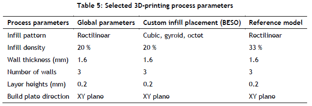
For topology optimisation methods to create custom infill structures using the FDM technology, the manufacturing constraints and the process parameters must be fully defined, as the mechanical performance depends on them. A survey by Dey and Yodo [14] investigated the impact of the FDM process parameters on dimensional accuracy, surface roughness, build time, and mechanical properties. Their survey screened 100 research articles from 2005 to 2019 to quantify the relationship between process parameters and 3D-printed part characteristics. Optimal process parameters were selected, based on their influence on the mechanical properties presented in Table 5, and used to 3D-print the test specimens in this study.
2.2. Structural optimisation
Structural topology optimisation is considered a procedure for optimising the topological material arrangement of a part in the design domain. This is archived by eliminating the material volume that does not contribute to the structure's integrity, while the optimised shape is generated on the basis of the material volume that experiences loading and specific boundary conditions [15]. Structural optimisation can be classified into three categories: 1) shape optimisation, 2) size optimisation, and 3) topology optimisation. This study used the BESO technique in TO, which allows the material to be removed and added simultaneously. The initial research on BESO was conducted by Yang et al. [16] for stiffness optimisation. The new BESO algorithm for stiffness optimisation [17] addresses many issues related to the TO of continuum structures. In the BESO method, a part or structure is optimised by removing and adding elements simultaneously, based on an initial FEA. The elements represented by the FEA mesh are treated as the design variable rather than the associated physical or material parameters. The equation sets for applying the BESO technique are presented in [18].
2.2.1. Smoothing technique for post-processing
The optimised model using the BESO technique contains boundary contours that are not streamlined and that are usually rough because of the mesh elements. This is a result of the element's shape and the BESO method of element removal. The optimised model (with zig-zag boundaries) could reduce structural performance and present manufacturing difficulties using the FDM technology. A smoothing technique was proposed by Yang et al. [19] for reconstructing the element-based model. In this study, the Laplacian mesh processing technique [20] was employed to make the optimised structure smooth enough to manufacture using FDM technology. Although the Laplacian smoothing algorithm is efficient and straightforward, it can produce an over-smoothed result. The triangular mesh was converted into a quadrilateral mesh by applying a 4-8 subdivision scheme before Laplacian smoothing was performed to prevent over-smoothing and element mesh loss. This introduced only a single vertex for each triangle instead of four [21].
3. INFLUENCING THE INFILL DESIGN USING BESO
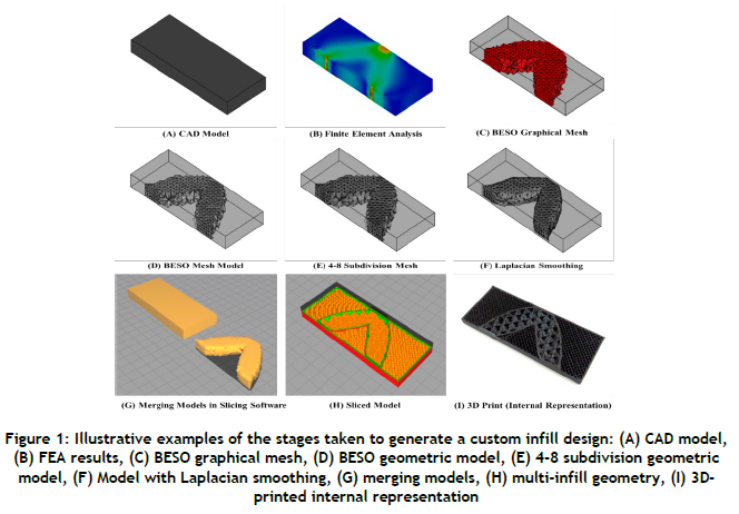
The key objective of the process was to use FEA results to influence the infill placement while ensuring that the external geometry was not altered. The process considers the manufacturing constraints of FDM according to different types of components. It allows for multi-infill geometry, and applies to different material types. The methodology involves a six-stage process to achieve an optimised infill geometry placement: 1) model construction, 2) mesh generation, 3) FEA analysis, 4) TO using BESO, 5) post-processing TO mesh, and 6) infill design. Figure 1 is a graphical representation of the custom infill placement workflow.
3.1. Model construction (Stage 1)
The initial step in creating a custom infill placement was to create the computer-aided design (CAD) model to be optimised. From this model, a finite element mesh (FEM) and the analysis were performed. A stereolithography (STL) file was also created to preserve the original external shape of the CAD, which was used during the infill design stage. In this study, FreeCAD 0.19 was used to create the CAD model, illustrated in Figure 1-A.
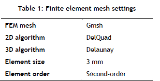
3.2. Mesh generation (Stage 2)
The FEM was created in FreeCAD's FEM workbench using the Gmsh open-source finite element mesh generator [22]. Since the BESO method adds and removes elements based on a stress criterion, the mesh element size determined the optimised shape. Table 1 lists the mesh algorithms used to set up the FEM for the test specimen.
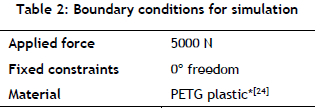
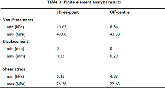
3.3. Finite element analysis (Stage 3)
The FEA was done using the CalculiX solver [23]. Table 2 illustrates the boundary conditions used to perform the simulation, and Table 3 presents the fEa results.
3.4. Topology optimisation using BESO (Stage 4)
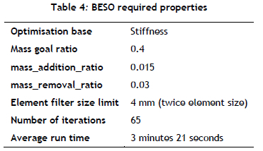
A custom-developed Python macro and graphical user interface (GUI), inspired by the algorithms described in [18], was used to perform the topology optimisation technique. The script interfaced with FreeCAD's workbench macros, which performed the BESO method [25]. The Python macro used the FEM created by Gmsh and the FEA results from the CalculiX solver as inputs. The macro performed the BESO method by iterating the removal of elements until the specified stress and mass criterion was achieved. Finally, the results from the tool created a native FreeCAD FEM graphical file and a .vtk file format for use in visualisation tool kits.
Further steps were required to create an STL model from the results file [26]. Further improvements and contributions by community members have been made to this open-source program in scripting the GUI and the testing methods [27]. In the case of this study, the plugin tool was used to perform the BESO method with minimal changes to the source code for the current application. Table 4 lists the changes made to the macro. Figure 1-C and Figure 1-D illustrate the final iteration of the BESO method for the three-point bending test specimen.
3.5. Post-processing topology optimised mesh (Stage 5)
This stage of the method post-processes the graphical representation of the BESO method (Figure 1-C) into a 3D model that is capable of being 3D-printed using the FDM process. The final FEM created by the BESO method was converted into a mesh geometry model natively in FreeCAD (Figure 1-D). The mesh geometry represented by elements was then converted into quadrilateral elements (Figure 1-E). Finally, Laplacian smoothing was applied to the quadrant mesh to create a smooth 3D-printable model with minimal changes to the optimised structural shape (Figure 1-F). Changes in the element shapes and smoothing were performed using MeshLab [28].
3.6. Infill design (Stage 6)
The sixth stage involves generating the infill structure and its related 3D-printing process parameters. To start, both the original CAD model and the BESO structure were imported into the slicer software. Both models were imported into Cura 4.7.1 as STL files in this study. The process parameters were then assigned for each model. Finally, both models were merged, and the print G-code was created. Figure 1-G illustrates the 3D models being merged, while Figure 1-H illustrates the multi-infill geometry assigned to the models.
3.7. 3D printing
Once the G-code had been created and sent to the 3D printer, the test specimen was 3D-printed with the optimised infill placement. Using a state-of-the-art slicer enabled a wide range of process parameters to be selected to optimise the 3D-printed part's mechanical performance compared with the work presented by [5]. Table 5 illustrates the process parameters used to 3D-print the test specimens in this study. Figure 1-H illustrates the internal 3D-printed version of the test specimen.
4. EXPERIMENTAL INVESTIGATION
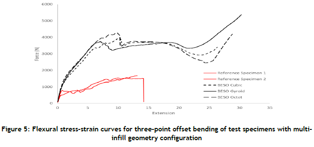
A beam undergoing two different loading scenarios - 1) three-point bending and 2) off-centre three-point bending - was tested to investigate the benefit of optimising the infill design using FEA and the BESO method. For this investigation, beams of 100 mm length, 40 mm height, and 10 mm depth were tested on a 25 kN Instron testing machine following the procedure presented in [5] and [6]. The specimens were tested to their stress-strain limits so that comparisons across the full extent of their structural behaviour could be determined. The tests were repeated for each case to determine an average set of results. Two comparative tests were performed. The first testing campaign investigated the mechanical performance of the test specimens printed solid (100%) and those printed with a multi-infill density configuration, with the BESO structure printed solid (100%) and the outer region using the rectilinear infill geometry (10%). The second testing campaign investigated the mechanical performance of the test specimens printed using the rectilinear infill geometry (33%) and the test specimens with a multi-infill geometry configuration for the BESO structure (20%). 3D infill patterns such as cubic, gyroid, and octet were used to print the BESO structure [29].
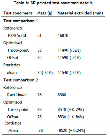
To control the conditions of the tests further, the mass remained constant at 28 grams for all of the optimised test specimens. Table 5 details the process parameters selected for printing the test specimens, and Table 6 provides the amount of deposited material used to 3D-print the test specimens. All of the test specimens were printed on the CR10S Pro, Creality FDM 3D printer.
5. RESULTS AND DISCUSSION
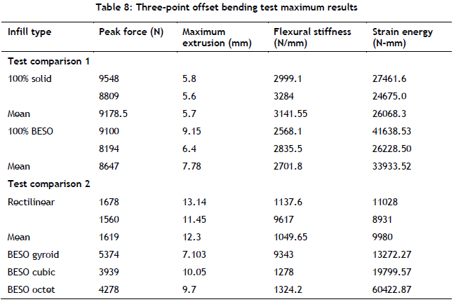
Table 7 and Table 8 provide the test results for the three-point bending and three-point offset bending tests.
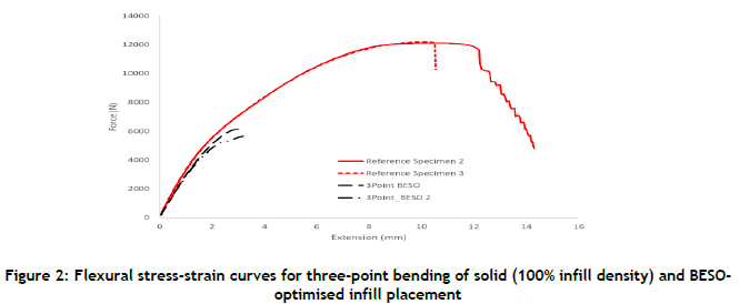
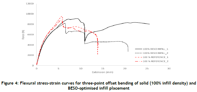
Figure 2 and Figure 4 illustrate the flexural force-extension results for the first investigative comparison, while Figure 3 and Figure 5 illustrate the force-extension results for the second investigative comparison.
5.1. Maximum loading capacity
Based on the first investigative comparison, it was evident that the solid (100% infill density) test specimens could withstand a larger loading capacity than the BESO-optimised infill for the three-point bending test. The BESO-optimised specimens failed before yielding, unlike the reference specimens. This was primarily because of the solid and porous infill density configurations. In the case of the three-point offset bending, the solid (100% infill density) BESO test specimens experienced a reduced loading capacity of 6% ((9178.5-8647)/9178.5) χ 100) with a mass reduction of 32% ((51-35)/51) χ 100) compared with the reference solid (100% infill density) test specimen. Based on the second investigative comparison, it was evident that the custom infill placement using multi-infill geometry produced test specimens capable of withstanding a larger loading capacity than the traditional rectilinear infill pattern.
5.2. Maximum force extension:
Considering the maximum specimen extension at which the peak force occurred, Table 7 and Table 8 show that the peak force occurred at a lower strain for all of the BESO-optimised infill placements than for the reference test specimens - although it was interesting to note that, in the second investigative comparison, the BESO-influenced infill placement saw the most significant reduction in the strain at increased peak forces, compared with the reference test specimens. The results showed that the BESO infill placement with a gyroid pattern tested using the three-point bending experienced a 49% (((2680 -3985)/2680) χ 100) increase in peak force with a 29% ((35518.63-25113.44)/35518.63) χ 100) reduction in strain, compared with the reference rectilinear infill specimen. Compared with the standard rectilinear infill geometry, there was a 66% ((26.5-9.15)/26.5) χ 100) reduction in peak force material extrusion for the octet pattern. In all of the cases of the BESO multi-infill geometry, the peak forces were increased with a reduction in strain. This is an essential factor in using multi-infill geometry patterns for failure modes when a component needs to fail at a particular strain. This allows multi-infill geometry to design functional components that may require specific operating strains.
5.3. Beam stiffness
In the first investigative comparison, it was evident that the solid test specimens performed better than the BESO-optimised solid infill. Although the BESO-optimised solid infill specimens did not match or surpass the reference test specimens, it is essential to note that a stiffness reduction of 11% ((2997.2-2672.55)/2997.2) χ 100) was achieved for the test specimens, which were 31.4% ((51-35)/51) χ 100) lighter than the solid reference test specimens. In the case of the second investigative comparison, it was evident that the BESO-optimised multi-infill geometry specimens outperformed the traditional rectilinear test specimens. The most significant stiffness increase (46% ((1079.9-1578)/1079.9) χ 100)) was achieved by the BESO octet infill geometry tested under three-point bending. This highlights the significance of loading scenarios when applying the BESO TO. The most significant changes in peak loading, strain at peak loading, and stiffness could have been influenced by applying specific infill geometries and more material at these locations.
5.4. Energy absorption
The BESO-optimised test specimens decreased strain energy in all of the test comparisons. In the case of the three-point offset bending tests, all of the BESO-optimised test specimens did not experience catastrophic failure, but instead began to experience compression. This was because of the placement of the BESO internal structure and the fixture rollers. This confirmed that components with a well-defined loading profile might benefit from an FEA-influenced infill design.
5.5. Failure modes of structures
When considering the failure modes of the specimens that were tested, some interesting buckling phenomena were experienced across both the BESO optimised and the traditional infill specimens. With the BESO-optimised specimens' stiffness increase, brittleness was also experienced. This was evident in the first investigative comparison between the solid test specimens and the solid BESO test specimens, which was captured clearly in the force-extension curves illustrated in Figure 2 and Figure 4. The reference rectilinear infill test specimens gradually failed during the testing process. The interruptions in the force-extension curves, presented in Figure 3, Figure 4, and Figure 5, show high internal stresses being released owing to the infill geometry before the whole part failed.
In contrast, the BESO multi-infill geometry optimised test specimens presented buckling events in the early stages of the testing process. These illustrated the internal failures where the shell walls, the BESO infill geometry, and the rectilinear infill patterns connected. The fixtures then settled in the optimised infill structure, where the loading capacity increased once again (Figure 3, Figure 4, and Figure 5). This was evident in the force-extension curves for the BESO gyroid test specimens. The consistency of the bucking points for the BESO-optimised specimens could support planned and predictable failure modes for parts, which could also assist in post-failure analysis.
6. RAILWAY APPLICATION - CUSTOM INFILL PLACEMENT
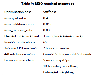
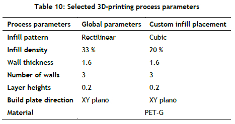
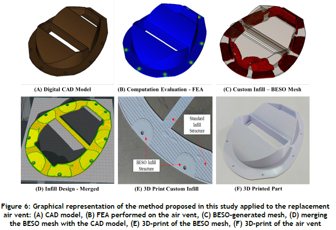
Toth et al. [8] presented a case study on designing, manufacturing, and installing a functional 3D-printed roof scoop air vent. The air vent unit was developed as a replacement part for a railway inspection vehicle owing to a shortage of spares. The unit had overall dimensions of 330 mm x 260 mm x 60 mm, and was printed on the CR10S Pro, Creality FDM 3D printer. The internal (infill) structure was optimised in designing the roof scoop air vent using this study's custom infill placement methodology. Table 9 and Table 10 present the BESO optimisation properties and the 3D-printing details for the roof scoop. Figure 6 is a graphical representation of applying the custom infill placement for optimising the roof scoop air vent. Owing to the layer-by-layer process, the 3D-printed vertical sections of the digital BESO mesh illustrated in Figure 6-C are difficult to represent as an image.
The selection, redesign, manufacturing, and installation of the functional 3D-printed air vent unit was based on a legacy component requiring replacement because it had failed [8], [9]. Computational fluid dynamic (CFD) simulations were performed to determine performance differences between the legacy and the new designs. The results showed an 18.7 % reduction in shear stress caused by air flow, attributed to the optimised architecture enabled by 3D printing [8]. The 3D-printed part was mounted using silicon adhesion and standard 6.5 mm diameter pop rivets. The BESO infill structure was placed in regions of elevated stress, including the fastening holes, owing to the compressive stresses induced by the installation method. The part was successfully installed and operated on the railway inspection vehicle.
7. CONCLUSION
Additive manufacturing technologies allow designers to optimise parts' external forms and internal structures. This study investigated the advantage of optimising the internal structures by creating custom infill placements based on the bi-directional evolutionary structural optimisation technique. Developing a custom infill placement based on stress profiles was discussed in detail with two case studies: a beam and a railway vehicle replacement component undergoing varied loading scenarios. A notable feature of the custom infill placement based on the part's stress profiles was its ability to assign multi-infill geometry combinations, including three-dimensional infill geometries. The proposed process has been experimentally evaluated for a rectangular beam under two loading cases in which the generated designs were compared with solid and rectilinear infill geometry. The test showed relative performance increases for all of the BESO-optimised multi-infill geometry test specimens compared with the reference rectilinear specimens. A 49% increase in peak loading for the gyroid-rectilinear infill geometry combination was achieved, compared with the standard rectilinear infill pattern. Compared with the standard rectilinear infill geometry, there was a 66% reduction in the peak force material extension needed for the octet-rectilinear infill geometry. A 46% increase in flexural stiffness for the octet-rectilinear infill geometry combination was achieved, compared with the standard rectilinear infill geometry and brittle material behaviour for solid BESO-infill-optimised test specimens.
ACKNOWLEDGEMENTS
We would like to thank Dr Velaphi Matjeke and his team at Transnet Freight Rail for providing access to laboratory facilities for conducting mechanical testing.
REFERENCES
[1] C. K. Chua, C. H. Wong and W. Y. Yeong, Standards, quality control and measurement sciences in 3D printing and additive manufacturing, 1st ed., United Kingdom: Elsevier Academic Press, 2017. [ Links ]
[2] M. Dzemko, B. Engelmann, J. Hartmann and J. Schmitt, "Toward shifted production strategies through additive manufacturing: A technology and market review for changing value chains," Procedia CIRP, vol. 86, pp. 228-233, 2019. [ Links ]
[3] T. Alsop, "Which 3D printing technologies do you use?," 2021. [Online]. Available: https://www.statista.com/statistics/560304/worldwide-survey-3d-printing-top-technologies/ [Accessed 10 06 2021]. [ Links ]
[4] A. Moussa, D. Melancon, A. El Elmi and D. Pasini, "Topology optimization of imperfect lattice materials built with process-induced defects via powder bed fusion," Additive Manufacturing, vol. 37, no. 101608, pp. 1-29, 2020. [ Links ]
[5] J. A. Gopsill, J. Shindler and B. J. Hicks, "Using finite element analysis to influence the infill design of fused deposition modelled parts," Progress in Additive Manufacturing, vol. 3, no. 2018, pp. 145163, 2017. [ Links ]
[6] J. A. Gopsill and B. J. Hicks, "Deriving infill design of fused deposition modelled parts from predicted stress profiles," in Proceedings of the ASME 2016 International Design Engineering Technical Conferences and Computers and Information in Engineering Conference IDETC/CIE 2016, Charlotte, North Carolina, 2017. [ Links ]
[7] A. D. Toth and S. Vilakazi, "Benefits of reinforced meshing and materials testing of 3D printed parts to assist mechanical design in the railway infrastructure environment," in RAPDASA 2019 Conference Proceedings, Bloemfontein, 2019. [ Links ]
[8] A. D. Toth, J. Padayachee, T. Mahlatji and S. Vilakazi, "Report on case studies of additive manufacturing in the South African railway industry," Scientific African, vol. 16, no. e01219, pp. 112, 2022. [ Links ]
[9] A. D. Toth, J. Padayachee, S. Vilakazi and V. Matjeke, "Analytic hierarchy process methodology in part selection for fused deposition modelling in the South African railway industry," Proceedings of the Institution of Mechanical Engineers, Part F: Journal of Rail and Rapid Transit, vol. 237, no. 6 pp. 1-9, 2022. [ Links ]
[10] A. D. Toth and J. Padayachee, "Sustainability in part selection for additive manufacturing in the South African railway industry using the fuzzy analytic hierarchy process," in Proceedings of the 12th International Heavy Haul Association Conference, Rio de Janeiro, Brazil, 2023. [ Links ]
[11] A. D. Toth and L. Msibi, "A conceptual evaluation and benefit of additive manufacturing technology to improve maintenance tasks in the railway industry," in Proceedings of the 11th International Heavy Haul Association Conference, Navik, Norway, 2019. [ Links ]
[12] A. D. Toth, J. Padayachee and S. Vilakazi, "Digital maintenance centre for additive manufacturing and 3D printing in the railway industry," in Proceedings of the South African Heavy Haul Association, Johannesburg, South Africa, pp. 254-261, 2021. [ Links ]
[13] Y. Xiong, D. Bao, X. Yan, T. Xu and Y. M. Xie, "Lessons learnt from a national competition on structural optimization and additive manufacturing," Current Chinese Science, vol. 1, no. 1, pp. 151-159, 2021. [ Links ]
[14] A. Dey and N. Yodo, "A systematic survey of FDM Process parameter optimization and their influence on part characteristics," Journal of Manufacturing and Materials Processing, vol. 3, no. 3, pp. 1-30, 2019. [ Links ]
[15] G. Kazakis, I. Kanellopoulos, S. Sotiropoulos and N. D. Lagaros, "Topology optimization aided structural design: Interpretation, computational aspects and 3D printing," Heliyon, vol. 3, no. 10, pp. 1-33, 2017. [ Links ]
[16] X. Y. Yang, Y. M. Xie, G. P. Steven and O. M. Querin, "Bidirectional evolutionary method for stiffness optimisation," AIAA Journal, vol. 37, no. 11, pp. 1483-1488, 1999. [ Links ]
[17] X. Huang and Y. M. Xie, "Evolutionary topology optimization of continuum structures including design-dependent self-weight loads," Finite Elements in Analysis and Design, vol. 47, no. 2011, pp. 942-948, 2011. [ Links ]
[18] X. Huang and Y. M. Xie, Evolutionary topology optimization of continuum structures: Methods and applications, First ed. West Sussex: John Wiley & Sons Ltd, 2010. [ Links ]
[19] K. Yang, Z.-L. Zhao, Y. He, S. Zhou, Q. Zhou, W. Huang and Y. M. Xie, "Simple and effective strategies for achieving diverse and competitive structural designs," Extreme Mechanics Letters, vol. 30, article 100481, 2019. [ Links ]
[20] A. Nealen, T. Igarashi, O. Sorkine and M. Alexa, "Laplacian mesh optimization," In Proceedings of the 4th International Conference on Computer Graphics and Interactive Techniques in Australasia and Southeast Asia, Kuala Lumpur, Malaysia, pp. 381-389, 2006. [ Links ]
[21] L. Velho and D. Zorin, "4-8 subdivision," Computer Aided Geometric Design, vol. 18, no. 5, pp. 397-427, 2001. [ Links ]
[22] C. Geuzaine and J.-F. Remacle, "Gmsh: A 3D finite element mesh generator with built-in pre and post-processing facilities," International Journal for Numerical Methods in Engineering, vol. 79, no. 11, pp. 1309-1331, 2009. [ Links ]
[23] K. Wittig, CalculiXuser's manual: CalculiXGraphiX, Version 2.17.1, 1st ed. CalculiX, 2020. [Online]. Available: http://www.dhondt.de/ccx_2.17.pdf [Accessed 05 10 2020]. [ Links ]
[24] Dielectric Manufacturing, "PETG," Dielectric Manufacturing. [Online]. Available: https://dielectricmfg.com/knowledge-base/petg/ [Accessed 05 10 2020]. [ Links ]
[25] F. Loffelmann, Failure index based topology optimization for multiple properties, In Proceedings of the 23rd International Conference on Engineering Mechanics, Svratka, Czech Republic, pp. 1518, 2017. [ Links ]
[26] F. Loffelmann, "Topology optimization, BESO method," 2020. [Online]. Available: https://github.com/fandaL/beso/wiki/Basic-description [Accessed 05 01 2021]. [ Links ]
[27] FreeCAD, Topology optimization, 2016. [Online]. Available: https://forum.freecadweb.org/viewtopic.php?f=18&t=15460&sid=cb7ead91b308240428c0b08a6e299422 [Accessed 05 01 2021]. [ Links ]
[28] P. Cignoni, M. Callieri, M. Corsini, M. Dellepiane, F. Ganovelli and G. Ranzuglia, "MeshLab: An open-source mesh processing tool," Eurographics Italian Chapter Conference, vol. 2008, pp. 129136, 2008. [ Links ]
[29] B. Goldschmidt, The best cura infill pattern (for your needs), 2021. [Online]. Available: https://all3dp.com/2/cura-infill-patterns-all-you-need-to-know/. [Accessed 05 05 2021]. [ Links ]
Submitted by authors 25 Feb 2023
Accepted for publication 24 Oct 2023
Available online 14 Dec 2023
* Corresponding author: padayacheej@ukzn.ac.za
ORCID® identifiers
A.D. Toth: https://orcid.org/0000-0003-4641-0964
J. Padayachee: https://orcid.org/0000-0003-0358-5289

