


Serviços Personalizados
Artigo
 Inglês (pdf)
 Artigo em XML
 Referências do artigo
Indicadores

Links relacionados
-
 Citado por Google
 -
 Similares em Google
Compartilhar

 Permalink
South African Journal of Industrial Engineering
versão On-line ISSN 2224-7890
versão impressa ISSN 1012-277X
S. Afr. J. Ind. Eng. vol.33 no.3 Pretoria Nov. 2022
http://dx.doi.org/10.7166/33-3-2795
SPECIAL EDITION
Strategy to identify and mitigate hazards in deep-level mine ventilation systems using a calibrated digital twin
D.R. Jacobs*; J.H. van Laar; C.S.L. Schutte
Department of Industrial Engineering, Stellenbosch University, South Africa
ABSTRACT
Deep-level mines have complex and dynamic ventilation systems to ensure that sufficient air is provided to underground workers. Certain changes to the ventilation systems are continually implemented to enable the deepening of these mines. The three main hazards in ventilation systems are high temperatures, dust pick-up, and gas buildup. This means that avoiding hazards in these systems is important for the health and safety of workers. New technologies, such as digital twinning, can be used to simulate and plan the entire deep-level mine ventilation network with ease. In this study, a digital twin is used to identify high-risk areas in a deep-level mine that are susceptible to high temperatures, dust-pick-up, and gas build-up. The identified hazards can now be avoided by implementing various changes to help mitigate the possibility of their occurrence. This enables the mining industry to plan proactively and to manage the ventilation system for the entire life-of-mine (LOM).
OPSOMMING
Diepvlakmyne het komplekse en dinamiese ventilasiestelsels om te verseker dat voldoende lug aan ondergrondse werkers verskaf word. Sekere veranderinge word voortdurend aan die ventilasiestelsels gei'mplementeer om die verdieping van myne moontlik te maak. Die drie hoofgevare in ventilasiestelsels is hoe temperature, skep van stof en die opbou van gas. Dit beteken dat die vermyding van gevare in hierdie stelsels belangrik is vir die gesondheid en veiligheid van werkers. Nuwe tegnologiee, soos digitale tweelinge, kan gebruik word om die hele diepvlakmynventilasienetwerk met gemak te simuleer en te beplan. In hierdie studie word 'n digitale tweeling gebruik om hoerisikogebiede in 'n diepvlakmyn te identifiseer wat vatbaar is vir hoe temperature, stofophoping en gasopbou binne 'n diepvlakmyn. Die geidentifiseerde gevare kan dan vermy word deur verskeie veranderinge te implementeer om die moontlikheid daarvan te verminder. Dit stel die mynbedryf in staat om proaktief te beplan en die ventilasiestelsel vir die hele lewe-van-myn (LOM) te bestuur.
1. INTRODUCTION
Deep-level mining is present in various countries around the world, such as the Republic of South Africa (RSA), Germany, Canada, Poland, China, and Russia [1]. In 2006, RSA was the number one gold producer in the world, but by 2009 it has dropped to fourth behind China, Australia, and the United States of America (USA) [2] [3]. The search for gold in RSA has meant that deep-level mines have had to expand deeper into the earth's crust, resulting in six of the top ten deepest mines in the world being located in RSA [4].
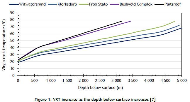
Various challenges exist when mining at these depths (up to 4 km) [5] [6]. The biggest challenges are ventilating the working areas, mitigating the heat generated through mining practices, and dealing with heat radiation from the high virgin rock temperatures (VRT) [7]. Figure 1 illustrates the increase in virgin rock temperature with depth below surface.
As deep-level mines in South Africa start to mine deeper into the earth, the mitigation of the heat within the mine is imperative for the health and safety of the workers [6][7][8]. The primary system that is used to mitigate heat is the ventilation system [6][7].
The ventilation system is one of the most complex systems of a deep-level mine, given its dynamic nature with small operational changes occurring every day [6]. The main components of a ventilation system are airways, fans, and seals [6]. With such a system as this, which is large in scale and contains numerous components, effective planning becomes vital for the health and safety of underground workers.
Ventilation planning in deep-level mining is revised regularly because of the continuous changes being implemented. The most important aspect of ventilation planning is to avoid certain hazards when changes to the system are implemented. The main hazards in deep-level mine ventilation systems are dust pollutants in the air, gas concentration build-up, and high temperatures [6]. There are various consequences when workers are exposed to these hazards:
• Silicosis from excessive exposure to silica dust [9].
• Combustion in underground working areas as a result of the concentrated build-up of gas such as methane [10].
• Heat stroke after being exposed to high temperatures for prolonged periods [8][11].
Various components in a ventilation system help to control and mitigate these hazards:
• Auxiliary fans that assist with airflow through working areas [12].
• Secondary and tertiary cooling systems that help to mitigate the heat in the ventilation system [13].
• Gas detection instrumentation to detect the presence of dangerous gases [6].
• Dust suppression nozzles that reduce the amount of dust pollutants in the air [14].
• Ventilation stoppings that seal off certain airways to prevent hot air from flowing into the areas where personnel are working [6].
In addition, guidelines from the Mine Ventilation Society of South Africa (MVSSA) outline the allowable limits of underground dust concentration, gas concentration, and temperature [6]. The Mine Health and Safety Act of 1996 also outlines actions to be taken if these limits are exceeded [15], and so ensure the safety of all the personnel working in the mine. The early identification and mitigation of hazards in deep-level mines is therefore of the utmost importance.
Current hazard avoidance methods entail the installation of sensors at strategic locations within the mine to monitor the system [6]. Specialised sensors can accurately detect when any of the above-mentioned elements exceed a pre-defined limit [16][17][18]. Unfortunately, this means that the hazard can only be addressed after it has been detected.
Consequently, there is a need for an effective hazard avoidance methodology to be applied in deep-level mining ventilation systems whenever new projects and changes are implemented. Nel et al. [19] proposed that an appropriate solution for such a complex system would be a digital planning tool to help to evaluate system changes and proactively to identify problem areas - i.e., a calibrated digital twin of the mne's entire ventilation network. Other countries have used software that can simulate ventilation systems [20]; but they do not have mines with the depth and complexity of South Africa's deep-level mines. The deep-level mine ventilation systems in South Africa require a more detailed approach in which every working area is simulated and illustrated. This means that ventilation planning in South Africa requires the use of a digital twin.
The definition of a digital twin has evolved over the years. It could be described as a cyber-physical copy of a physical system [21]. There are also instances in which a digital twin is viewed as the monitoring platform of a system [22][23]. This study, however, refers to a digital twin as a calibrated model of a system that reacts in the same way as the physical system when changes are applied. The technology used in this study to create a digital twin is called Process Toolbox (PTB). It is a one-dimensional computational fluid dynamics (CFD) solver that solves complex thermo-hydraulic networks. The software can simulate incompressible, compressible, and two-phase fluids. PTB has the capability to simulate a transient, integrated cooling and ventilation network of an underground mine. It has been used in previous studies to simulate various deep-level mine ventilation systems accurately [19][24] [25].
This study aims to develop a framework to identify and mitigate hazards in deep-level mining with the use of a digital twin. This framework must be able to:
• identify certain problem areas in a deep-level mine ventilation system;
• determine the cause and the reason why the area is problematic; and
• propose effective mitigation strategies/solutions for the identified hazards.
The developed methodology is applied to a deep-level mine case study in South Africa.
2. METHOD
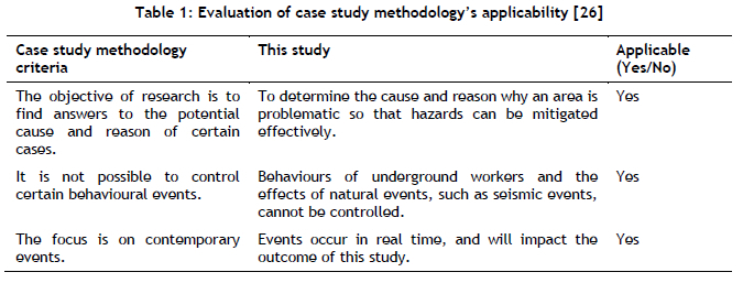
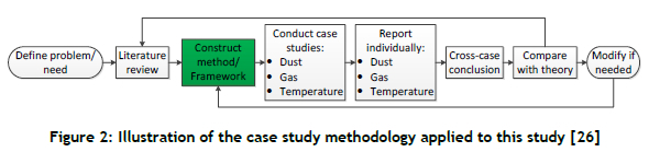
To address all the objectives, a case study methodology is applied [26]. To evaluate whether the case study methodology is sufficient for this study, Table 1 evaluates the criteria for using a case study.
Table 1 shows that the case study methodology is applicable here. Figure 2 illustrates the case study methodology used to address the main objectives of this study.
The method constructed in the process of using the case study methodology (green block in Figure 2) is the main outcome of this study. The method can be used to identify and mitigate the various hazards in a ventilation system.
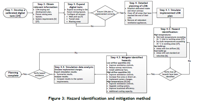
Figure 3 illustrates the final developed method/framework, and describes the steps to identify and mitigate all potential problem areas in the mining ventilation system. The development of the method/framework is discussed along with the results in the Results section.
3. RESULTS
The method illustrated in Figure 3 has been implemented step-by-step in a case study of the life-of-mine (LOM) planning on a deep-level gold mine (Mine A). This method is discussed in detail by illustrating the key results for each step and how the results were obtained.
Step 1: Develop a calibrated digital twin
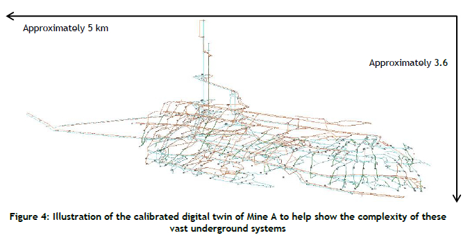
The process starts by developing a calibrated digital twin of the ventilation system. This step enables the accurate simulation of the actual ventilation system. The development and calibration of the digital twin follows the method developed previously by Jacobs (2020) [27]. The validation of the accuracy of the digital twin is conducted when comparing the results of the simulation under known conditions with the performance of the actual system [28]. This method yields results to within 95% accuracy of a real-time mining ventilation system, which is acceptable given the size and scale of the model [27][29]. Figure 4 is a graphical representation of the digital twin developed for this study.
This digital twin reacts in the same way as the current actual system, and now needs to be expanded according to the LOM plan.
Step 2: Obtain relevant information
The digital twin can only be expanded once the correct information is obtained. This information includes the following:
Step 2.1: The LOM stoping and development plan
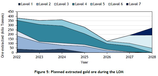
The LOM stoping and development plan includes information such as the face length, face width, face advance, ore grade, and expected rock density for the entire LOM. This can then be used to derive the planned extracted tonnes during the LOM. Figure 5 illustrates the planned tonnes of ore extracted for the LOM of Mine A.
Figure 5 shows the planned tonnes of ore extratcted for each level during the LOM. This is very important, since this indicates where they plan to mine. However, the detailed stoping and development plan goes into more detail, and shows the planned tonnes per panel. The planning for each year is done for the period within the year in which they are at peak production.
Step 2.2: The layouts of the future mining areas
The planned working areas of a mine should be designed by the mine's planning department. This means that these layouts could be used to expand a digital twin and to simulate the performance of the working areas even before they are developed. Figure 6 shows an example of the planned expansion of a mining level.
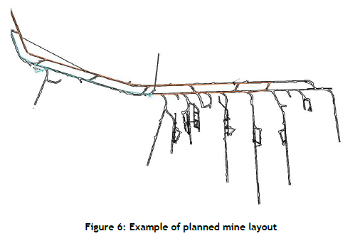
The orange line in Figure 6 shows where the current digital twin ends. This means that all the non-orange areas are where the mine is planned to expand.
Step 2.3: The requirements from the system
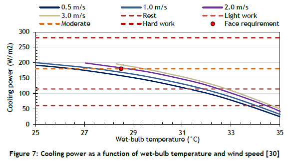
The LOM layout and progression is now established, and the next information that is required is the effective ventilation requirements for the working areas. These are determined by evaluating the metabolic rates of the mining personnel completing certain tasks for an average full shift [30]. It has been determined that the metabolic rate of a driller and of a drill assistant is the highest at ± 180 W/m2 [30]. Figure 7 illustrates the metabolic rate of different work rates compared with the cooling power of air as a function of wet-bulb temperature and time [30].
Figure 7 shows the point at which a driller will operate at the design face wet-bulb temperature of 28.5 °C. This indicates that the airflow requirement at the face of a working area will be an airflow velocity of 2 m/s. It should also be noted that only areas with a stagnant flow would be at risk of gas build-up from blasting. This means that, for a stoping width of 1.2 m and a distance from face to support of 5 m (which equates to a flow area of 6 m2), the required quantity into a working area should be a minimum of 12 m3/s. However, this study assumes a worst-case scenario, and uses a design airflow quantity of 15 m3/s and stope intake of wet-bulb temperature of 26°C to ensure sufficient air supply to all working areas. This ensures that no working area is at risk of high temperatures or a gas build-up.
The current infrastructure is evaluated to determine whether it can supply the amount of air required for the LOM plan. This is done by quantifying the amount of air required for all planned working areas in peak production in the planned year, and comparing it with the current quantity that can be supplied by the fans installed in the mine.
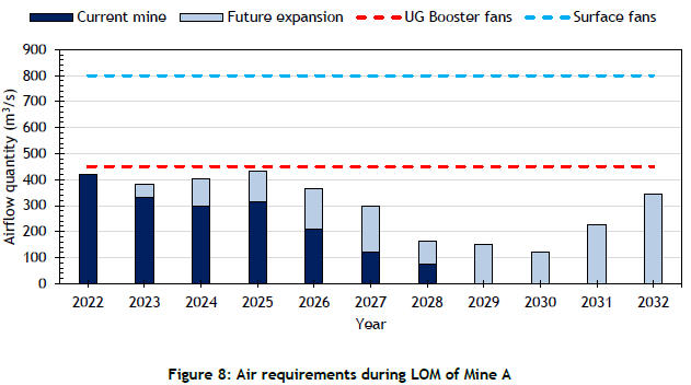
The design airflow quantity is used, therefore, to determine the airflow requirements for the next ten years of the LOM plan. Each year is evaluated at peak production, meaning that the worst-case scenario is always considered. Figure 8 illustrates the air requirements during the LOM compared with the amount of air that can be supplied by the current infrastructure.
Figure 8 shows that the current installed infrastructure will be able to accommodate the air requirements during the LOM of the current system, and that the future expansion project will take over from 2027. This means that no upgrades will be required to the main ventilation infrastructure of Mine A.
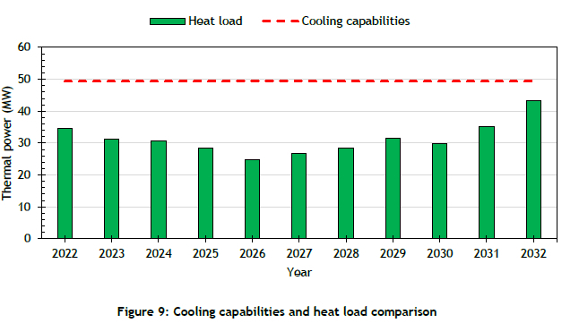
The next step is to determine whether enough cooling is installed to accommodate the heat load of the mine during Mine A's LOM. The heat load is assessed by determining the heat added to the system by the auto compression of the air, mining practices, fissure water, and the metabolic heat from underground workers. This heat load should then be compared with the cooling capabilities of the current infrastructure. Figure 9 illustrates the cooling capabilities compared with the heat load during peak production in each year in the LOM plan.
Figure 9 shows that the current infrastructure will be able to accommodate the heat load for the next ten years in the LOM plan. This means that no changes have to be made to the main infrastructure of Mine A.
Step 3: Expand the digital twin
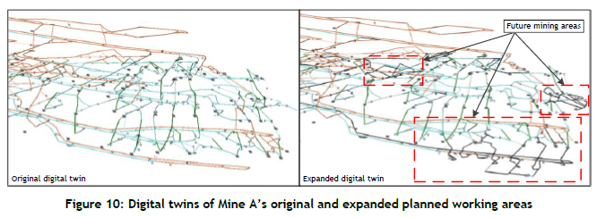
The calibrated digital twin is now expanded by using the obtained information. This step mainly focuses on building the planned working areas that are not in the current digital twin. This includes the configuration of the airways to simulate accurately the heat pick-up, air velocities, and blasting areas. Figure 10 illustrates the current and expanded planned working areas respectively.
Figure 10 shows how the digital twin is expanded. The planned areas are shown in black. These areas are then configured to the correct size, VRT, moisture exposure, heat pick-up, and friction factors. The digital twin is then expanded, and the next stage of the planning method can begin.
Step 4: Detailed planning of LOM
This section follows steps 4.1 to 4.4 in Figure 3. The results from Step 2.3 illustrated that there is enough cooling and air supply for the LOM plan, which means that the next step is to distribute the existing ventilation capacity effectively to the planned working areas. This step, however, focuses only on the next three years to limit the amount of detail presented in the results. The first iteration of the simulation is to close the working areas that are not part of the plan during peak production and to open the areas that are set to be active. This illustrates the natural distribution of the air without the interference of additional ventilation controls. It is also important to see that there is a dedicated intake and return airway for each working area.
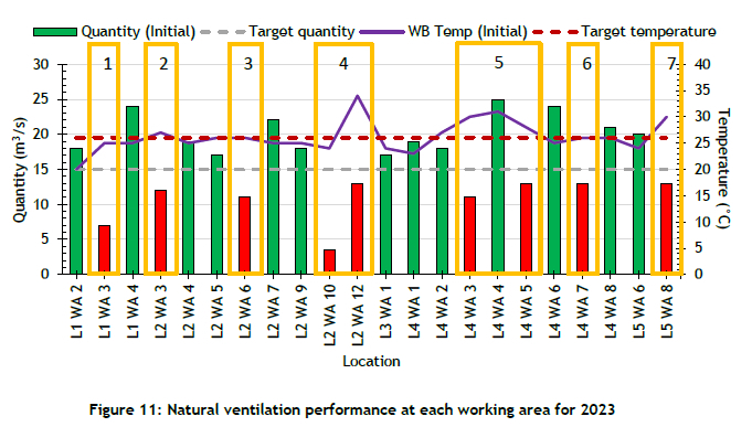
The system is then evaluated to determine the air flow distribution on each level, and where air might be wasted or short-circuited to the return airways. The naming convention used to identify each working area is a level-working area-number (Lx WA y), with level 1 being the upper level and level 5 being the deepest level. The working areas are then numbered in ascending order according to their distance from the shaft. Figure 11 illustrates the natural flow and wet-bulb (WB) temperature of air to the working areas of 2023. The bars indicate the air flow quantity to each working area, where green indicates that the target has been reached and red indicates that there is an insufficient quantity of air flow.
Figure 11 shows the seven problem areas that can easily be identified. It should be noted that most of the areas with sufficient airflow and temperature were already active in 2022, which meant that they already had sufficient ventilation controls. It is also important to take the cost of each of the primary ventilation controls into account when deciding which changes to implement. Table 2 shows the estimated cost-per-unit of the primary ventilation controls.
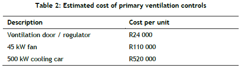
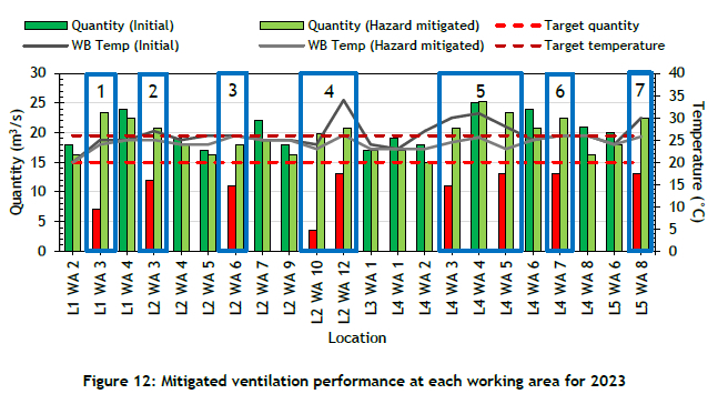
Table 2 shows the estimated cost of each of the primary ventilation controls, although these vary depending on the supplier. Taking this information into account, the problem areas are then investigated in the digital twin, and it is determined that the best way to improve the quantity is to install a 45 kW fan at the entrance to the working area to help to overcome the resistance through the working areas, and so increase the airflow quantity. It should be noted, however, that no areas are at risk of gas build-up.
The areas that have had temperature and quantity issues have been improved by moving existing heat exchangers closer to those areas, and using the 45 kW fan already attached to the heat exchanger to increase the quantity. This is done by ensuring that the heat exchanger discharges through a ducting or pipe through a wall at the entrance to the working area. This also ensures a reduced recirculation of air through the heat exchanger, and lowers the cost of the changes that are to be made to the actual system. These steps are then simulated to quantify the impact on the working areas. Figure 12 illustrates the improvement to the system by implementing these actions.
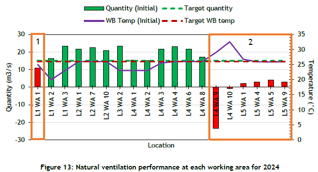
Figure 12 shows that all the problem areas have been addressed and the hazards have been mitigated. Figure 13 illustrates the natural flow and WB temperature of air to the working areas predicted for 2024.
Figure 13 shows that various areas have insufficient airflow quantities and that there are two working places where return air is pushed out into the intake airway, resulting in high temperatures. It could also mean that the carbon monoxide (CO) produced from blasting these areas could flow back into the intake airways.
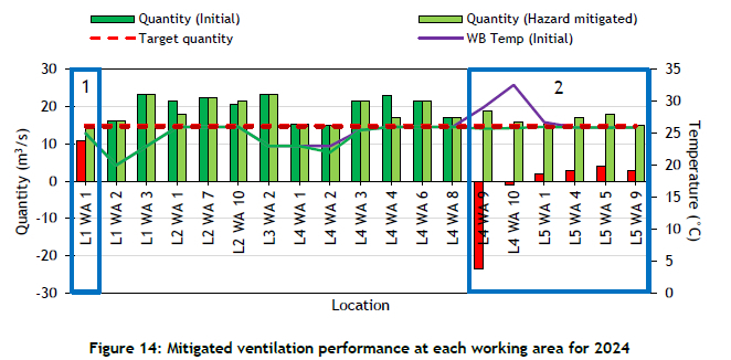
It should be noted that L5 WA 1, L5 WA 4, L5 WA 5, and L5 WA 9 are not connected to the upper levels, which means that they are not under the negative pressure supplied by the upper booster fans. Thus air should be supplied to these areas by means of force fans. This is done by installing two 22 kW fans and a ventilation door. The airflow quantity at L1 WA 1 is improved by implementing an improved sealing plan on level 1. The L4 WA 9 and L4 WA 10 reverse flow is solved by installing two 45 kW fans and ventilation doors to overcome the resistance through the working areas. Figure 14 illustrates the improvement to the system as simulated by the digital twin.
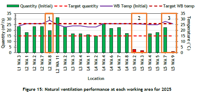
Figure 14 shows that all the problem areas are addressed and that a sufficient airflow and WB temperature is supplied to the working areas. Figure 15 illustrates the natural flow and WB temperature of air to the working areas for 2025.
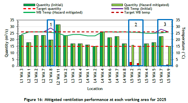
Figure 15 shows that the requirements of most of the working areas are met; however, some problem areas are still identified by the digital twin. No areas present the risk of gas build-up, since none of the areas have stagnant airflow. L2 WA 8 has insufficient cooling, and so a 500-kW heat exchanger is installed near the entrance to the working area. L5 WA 2, L5 WA 3, and L5 WA 9 have the same issue as previously mentioned: those working areas are not holed with the upper levels. This too is solved by installing two 22 kW force fans to help ventilate the working areas. Figure 16 illustrates the improvement to the system as simulated by the digital twin.
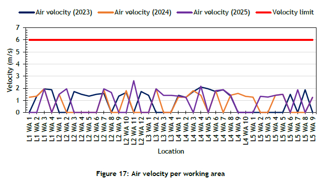
Figure 16 shows that the problem areas have been addressed effectively and that a sufficient airflow and WB temperature is supplied to the working areas. It is now important to evaluate the airflow velocity for each working area intake to ensure that the 6 m/s limit for dust control is not exceeded. Figure 17 illustrates the air velocity at the intake tunnel of each working area.
Figure 17 shows that none of the working areas exceed the limit, indicating that no areas risk having significant dust control issues. It is important to note that regular floor treatment and other mandatory dust control devices remain in place.
The results obtained in this case study show the value of having a calibrated digital twin. The digital twin was able to identify areas that were at risk of experiencing high temperatures and low airflows. This is valuable in the planning phase, since it shows that hazards can be proactively avoided or mitigated, ensuring that the health and safety of all underground workers is protected and prioritised. This process can be expanded to the rest of the LOM plan.
4. CONCLUSION
The expansion of deep-level mining in South Africa leads mines ever deeper into the earth. This presents various challenges in ventilating them effectively, and emphasises the importance of proper ventilation planning. A calibrated digital twin of a deep-level mine can be used in planning such a mine's LOM.
The case-study methodology was used to obtain an effective method that could be used in planning the LOM ventilation strategy. This method was then implemented on a deep-level mine to demonstrate its feasibility.
The method proved effective, and was able to identify potential problem areas where hazards might occur. These hazards were then mitigated, and all working areas throughout the three-year LOM plan would be sufficiently ventilated.
REFERENCES
[1] H. Xie, H. Konietzky, & H. W. Zhou, "Special issue 'Deep mining'," Rock Mechanics and Rock Engineering, vol. 52, no. 5, pp. 1415-1416, May 2019. [ Links ]
[2] A. Ruffini, "The decline of South African gold mining," Engineering & Mining Journal, vol. 211, no. 5, pp. 30-35, 2010. [ Links ]
[3] Statistics South Africa, "Mining: Production and sales. Statistics South Africa, Technical Report," 2020. [Online]. Available: http://www.statssa.gov.za/publications/P2041/P2041December2020.pdf. [Accessed: 2021/01/09] [ Links ]
[4] Mining Technology, "The top ten deepest mines in the world," 2019. [Online]. Available: https://www.mining-technology.com/features/feature-top-ten-deepest-mines-world-south-africa/. [Accessed: 2021/11/09] [ Links ]
[5] R. L. Lowrie, Mining reference handbook. Littleton, Colorado, United States of America. Society of Mining, Metallurgy and Exploration, 2009. [ Links ]
[6] M. J. McPherson, Subsurface ventilation and environmental engineering. Dordrecht: Springer Netherlands, 1993. [ Links ]
[7] R. Hemp, "Sources of heat in mines," in Ventilation and Occupational Environment Engineering in Mines, 3rd ed., J.J.L. Du Plessis, Johannesburg: Mine Ventilation Society of South Africa, 2014, pp. 569-612. [ Links ]
[8] P. Roghanchi & K. C. Kocsis, "Challenges in selecting an appropriate heat stress index to protect workers in hot and humid underground mines," Safety and Health at Work, vol. 9, no. 1, pp. 10-16, Mar. 2018. [ Links ]
[9] S. Dhatrak & S. Nandi, "Assessment of silica dust exposure profile in relation to prevalence of silicosis among Indian sandstone mine workers: Need for review of standards," American Journal of Industrial Medicine, vol. 63, no. 3, pp. 277-281, Mar. 2020. [ Links ]
[10] A. E. Dursun, "Statistical analysis of methane explosions in Turkey's underground coal mines and some recommendations for the prevention of these accidents: 2010-2017," Natural Hazards, vol. 104, no. 1, pp. 329-351, Oct. 2020. [ Links ]
[11] V. F. Nunfam, K. Adusei-Asante, E. J. van Etten, J. Oosthuizen, S. Adams, & K. Frimpong, "The nexus between social impacts and adaptation strategies of workers to occupational heat stress: A conceptual framework," International Journal of Biometeorology, vol. 63, no. 12, pp. 1693-1706, Dec. 2019. [ Links ]
[12] D. J. de Villiers, M. J. Mathews, P. Maré, M. Kleingeld, & D. Arndt, "Evaluating the impact of auxiliary fan practices on localised subsurface ventilation," International Journal of Mining Science and Technology, vol. 29, no. 6, pp. 933-941, Dec. 2019. [ Links ]
[13] X. Nie, X. Wei, X. Li, & C. Lu, "Heat treatment and ventilation optimization in a deep mine," Advances in Civil Engineering, vol. 2018, pp. 1 -12, Aug. 2018. [ Links ]
[14] H. Wang, C. Wang, & D. Wang, "The influence of forced ventilation airflow on water spray for dust suppression on heading face in underground coal mine," Powder Technology, vol. 320, pp. 498-510, Oct. 2017. [ Links ]
[15] Mine Health and Safety Council, "Mine Health and Safety Act 29 of 1996 and Regulations final booklet," no. 29, p. 199-203, 2018. [ Links ]
[16] S. Pamukcu & L. Cheng, Eds, Underground sensing: Monitoring and hazard detection for environment and infrastructure. London, United Kingdom, Academic Press, 2018. [ Links ]
[17] D. Yuyuan, Z. Nan, J. Changlong, T. Shoufeng, & T. Minming, "Treatment of underground dust concentration detection signal and FPGA implementation," In IOP Conference Series: Earth and Environmental Science, vol. 358, p. 022022, Dec. 2019. [ Links ]
[18] A. Jha & P. Tukkaraja, "Monitoring and assessment of underground climatic conditions using sensors and GIS tools," International Journal of Mining Science and Technology, vol. 30, no. 4, pp. 495-499, Jul. 2020. [ Links ]
[19] A. J. H. Nel, J. C. Vosloo, & M. J. Mathews, "Evaluating complex mine ventilation operational changes through simulations," Journal of Energy in Southern Africa, vol. 29, no. 3, pp. 22-32, 2018. [ Links ]
[20] N. Lilic, I. Obradovic, & R. Stankovic, "A knowledge-based approach to mine ventilation planning in Yugoslav mining practice," Mineral Resource Engineering vol. 11, no. 04, pp. 361-382, Dec. 2002. [ Links ]
[21] W. Yang, K Yoshida, & S. Takakuwa, "Digital twin-driven simulation for a cyber-physical system in Industry 4.0 era," in DAAAM International Scientific Book, 1st ed., vol. 16, B. Katalinic, Ed. Vienna: DAAAM International, 2017, pp. 227-234. [ Links ]
[22] M. N. Sishi & A. Telukdarie, "Implementation of Industry 4.0 technologies in the mining industry: A case study," International Journal of Mining and Mineral Engineering, vol. 11, no. 1, p. 1-22, 2017. [ Links ]
[23] V. V. Cheskidov, A. V. Lipina, & I. A. Melnichenko, "Integrated monitoring of engineering structures in mining," Eurasian Mining, vol. 2018, no. 2, pp. 18-21, 2018. [ Links ]
[24] D. Nell, "Practical determination of heat loads for existing deep level gold mines," Ph.D. Thesis, North West University, South Africa, 2019. [ Links ]
[25] P. Maré, "Novel simulations for energy management of mine cooling systems," Ph.D. Thesis, North West University, South Africa, 2017. [ Links ]
[26] S. Teegavarapu, J. D. Summers, & G. M. Mocko, "Case study method for design research: A justification," In ASME 2008 International Design Engineering Technical Conferences and Computers and Information in Engineering Conference, vol. 4, pp. 495-503, Aug. 2008. [ Links ]
[27] D. R. Jacobs, "Developing a digital twin for addressing complex mine ventilation problems," Masters Dissertation, North-West University, South Africa, 2020. [ Links ]
[28] A. Maria, "Introduction to modeling and simulation," in Proceedings of the Winter Simulation Conference, State University of New York, Binghamton, pp. 7-13, 1997. [ Links ]
[29] M. Motzev, "Prediction accuracy: A measure of simulation reality," Vanguard Scientific Instruments in Management, vol. 15, no. 1, pp. 4-13 2019. [ Links ]
[30] J. M. Stewart, M. Se, & B. Se, "Heat transfer and limiting physiological criteria as a basis for the setting of heat stress limits," Journal of the South African Institute of Mining and Metallurgy, vol.81, no. 8, pp. 239-251, 1981. [ Links ]
* Corresponding author: rjacobs@rems2.com
ORCID® identifiers
D.R. Jacobs: 0000-0001-6437-4595
J.H. van Laar: 0000-0003-0457-328X
C.S.L. Schutte: 0000-0002-0119-720X

