


Services on Demand
Article
 English (pdf)
 Article in xml format
 Article references
Indicators

Related links
-
 Cited by Google
 -
 Similars in Google
Share

 Permalink
South African Journal of Industrial Engineering
On-line version ISSN 2224-7890
Print version ISSN 1012-277X
S. Afr. J. Ind. Eng. vol.32 n.4 Pretoria Dec. 2021
http://dx.doi.org/10.7166/32-4-2590
GENERAL ARTICLES
An experimental approach to improving the joint stiffness of industrial robots through dexterous posture identification
A.P. Singh*; J. Padayachee; G. Bright
Department of Mechanical Engineering, University of KwaZulu-Natal, South Africa. A.P. Singh: https://orcid.org/0000-0003-4594-8922; J. Padayachee: https://orcid.org/0000-0003-0358-5289; G. Bright: https://orcid.org/0000-0003-4386-0329
ABSTRACT
Improving a robot's posture enables it to perform with greater accuracy and repeatability. A stiffer posture also protects the robot from unnecessary vibrations and deflections that may be induced by an applied load. This paper presents a method for choosing high stiffness robot postures. The method is demonstrated on a six-degree-of-freedom Fanuc M10-iA serial manipulator. The posture identification and stiffness modelling were achieved by a reliable and cost-effective alternative to deflection measurement using IEPE accelerometers.
OPSOMMING
Deur 'n robot se postuur te verbeter kan beter akkuraatheid en herhaalbaarheid behaal word. 'n Stywer postuur beskerm ook die robot teen onnodige vibrasies en defleksies wat deur 'n toegepaste lading induseer mag word. Hierdie artikel bied 'n metode aan om hoë styfheid robot posture te kies. Die metode word aan die hand van 'n ses vryheidsgrade Fanuc M10-iA serie manipulator gedemonstreer. Die postuur identifikasie en styfheidsmodellering is behaal deur middel van n betroubare en koste-effektiewe alternatief wat gebruik maak van IEPE versnellingsmeters eerder as defleksiemeting.
1 INTRODUCTION
Serial kinematic machines (SKMs) date back to the beginning of the industrial revolution, when the primary objective was to replicate the human arm by pushing and pulling objects [1]. Modern-day advancements have shifted robotic paradigms to complex manufacturing operations. Serial robots are used to perform light machining tasks that would otherwise be performed by computer numerically controlled (CNC) machines. These are attractive to manufacturers owing to their extended workspace, reachability, and flexibility [2]. Nevertheless, the lower stiffness of serial robots limits their ability to perform machining or precision placement tasks on high loads. A study of serial robotic stiffness began in the early 1980s by Salisbury [3], who developed a method of actively controlling the apparent stiffness of serial manipulators. 'Stiffness' is defined as the ability of a manipulator to sustain loads without excessive changes to its geometry [4, 5], and research into robotic stiffness remains of interest to manufacturers and academics. The adoption of serial robots for high-precision manufacturing tasks is limited in the manufacturing sectors because of insufficient control techniques to improve robot posture and stiffness. Researchers who have focused on this problem include Guo, Dong and Ke [6], Sellami and Respall [7], and Cvitanic, Nguyen and Melkote [8].
The stiffness of serial robots is dependent on the geometric and material properties of the links, the characteristics of the actuator and transmission elements, and the robot's posture. Stiffness, when referring to kinematic machines, is the accuracy required to satisfy the anticipated force and position commands [9, 10]. According to Alici and Daniel [11, 12], mechanical stiffness has been the most critical performance indicator of robotic systems. The architectural design of the SKM is ruled by its ability to manipulate its tool precisely, and doing so requires high rigidity to limit positioning errors that are due to external loads [13]. The inadequate posture control of SKMs compromises their structural rigidity when performing complex machining or precision placement tasks.
In existing robots, posture control is the primary method of manipulating stiffness [14]. Several analyses in the literature have identified compliance minimisation through posture control as a crucial concept for high accuracy applications [15]. Owen, Croft and Benhabib [16] suggest that posture control places the emphasis on reducing the cantilever effect of the robot's links on the actuated joints. Cheng, Peng, Yan, Li and Fan [17] further suggest that the selection of appropriate robot postures or joint configurations results in an improved stiffness profile. According to Xaud [18], Celikag, Sims and Ozturk [19], and Mousavi et al. [20], the dynamic and static properties of SKMs are configuration-dependent.
To address the low stiffness problem, this research provides a straightforward, low-cost dexterous posture identification method. Any manufacturer or roboticist can adopt the method to optimise their robot postures and ensure improved stiffness, accuracy, and repeatability during precision and high-loading manufacturing tasks. By locating optimal postures, the induced stresses can be regulated throughout the robot's structure, thereby improving process accuracy and repeatability. These aspects are related to the magnitude of the end-effector deflections. Apart from the improved stiffness, the method minimises maintenance by reducing excessive stresses on the robot's motors, joints, and links.
The method presented in this research identifies optimal poses using an inverse kinematic (IK) technique and the virtual joint modelling (VJM) approach. The IK technique considers appropriate joint positions that enable effective manoeuvrability of the robot at a point in space. This improves the actuation and load-bearing capacity of each joint during manufacturing tasks. The VJM technique provides a simple approach to modelling joint stiffness. A one-dimensional (1-D) virtual spring was used to model the complicated electromechanical design of the robot joints, providing a simple approach to modelling the joint stiffness. The lumped presentation of the joint stiffness drastically simplified the identification of robot stiffness, compared with alternative methods such as finite element analysis (FEA) and matrix structure analysis (MSA).
This paper presents a unique approach that combines dexterity analysis and VJM. Section 2 presents the dexterous workspace identification. Section 3 describes the stiffness analysis using the virtual joint method, which includes the modelling approach and the procedure for determining the joint stiffnesses. Section 4 describes the testing procedure. Section 5 presents the experimental results and analysis. Section 6 provides a discussion of the results, and Section 7 concludes with insights drawn from the research and with future recommendations.
2 DEXTERITY ANALYSIS
Manipulator dexterity analysis was performed to identify permissible joint ranges in terms of Euler angles (a,ß and y) at various points in the SKM workspace. Thereafter a stiffness analysis was performed using the virtual joint method (VJM) and the corresponding end-effector deflection. The aim of the dexterity analysis was to identify high-stiffness areas and to simplify the stiffness formulation.
According to Abdel-Malek et al. [21], to identify admissible orientations of a robot's end-effector at any user-defined point, a service sphere must be defined around the point. The sphere has a radius equivalent to the length of the manipulators' last link. Possible orientations can be determined by assessing all reachable points by the second-to-last joint (SLJ) of the robot without shifting the target position. The SLJ comprises an interior and exterior space boundary, and its intersection with the service sphere defines the service region. This region defines the feasible penetration orientation of the robot's last link into the service sphere, which permits all possible orientations of the end-effector to be determined. This intersection will be referred to as a dexterous 'bubble' in this paper. In the work of Abdel-Malek et al. [21], a continuation technique was implemented to find the intersection of the SLJ with the service sphere.
The dexterity formulation in this research adopted an analytical technique similar to that presented by Mondragon [22]. The inverse kinematic (IK) solution was based on two fundamental concepts: a clear case develops the required coordinate position within the robot's workspace, and a second case has the correct orientation. The IK solution for the robot used in this analysis was similar to that used by Mondragon [22].
3 STIFFNESS ANALYSIS USING THE VIRTUAL JOINT METHOD
3.1 The virtual joint method
The stiffness identification procedure in this research used the concept of 'virtual springs' outlined in the virtual joint method (VJM). According to Klimchik [23], the advantage of the VJM is its ability to represent accurately the stiffness components of a robot and to simplify the modelling approach. Currently, this is the most popular method to model the stiffness of serial industrial robots.
A fundamental step in the VJM technique is defining the virtual spring parameters. According to Pigoski [24], each actuated joint is assumed to be represented by a single one-dimensional virtual spring. Majou [25] added to Pigoski's work by considering the link flexibilities of a parallel kinematic machine. Apart from modelling the actuated joints and link compliance, Hu, Wang and Pang [26] improved the VJM's accuracy by employing two virtual joints to account for bearings and other structural components. The study focused on actuated and passive joints with the inclusion of translational and rotational effects of the links, which were replaced by virtual springs. Recent research incorporates six-dimensional (6-D) virtual springs in the model, using the FEA method. Combining both methods increases the VJM's accuracy, and the results can be compared with the accuracy of the FEA method [27].
Salisbury [3] developed the first closed-form solution for the Cartesian stiffness matrix by assuming that the robot's mechanical elasticity came from the actuated joints. The method was based on an extension of the conventional rigid body model of a robotic manipulator, in which the links are assumed to be rigid and the joints compliant, in order to accrue every possible flexibility in the joints only. This matrix forms the basis for manipulator stiffness analysis. The conservative congruency transformation (CCT) method was used to define the joint and Cartesian stiffness matrices.
According to Knapczyk and Ryska [28], two methods were developed to obtain the Cartesian stiffness matrix of a serial manipulator. The first method involved clamping all joints except one to measure the robot's elastic deflection under an applied wrench (force/torque). The joint stiffness matrix was developed by repeating the procedure for each joint; thus only six experiments were required to model a six-degree-of-freedom (DOF) manipulator. The second method focused on measuring the linear and rotational displacements of the end-effector owing to an applied wrench via some interpolations. The latter method was preferred, as it provided accurate results and was safer; as a result, this technique was applied in this research.
In the method proposed by this research, the serial manipulators' reaction to an applied wrench (force/moment) under static equilibrium was evaluated through the Cartesian stiffness matrix of the robot. The matrix was a precursor to finding solutions to the linear and angular deflections of the robot's end-effector in its joints and links when exposed to an externally applied wrench. The deflections of a robotic manipulator are owing to both its link and joint flexibilities. However, the joints account for most of the flexibility in the robot.
3.2 Joint stiffness modelling
This section presents the procedure to calculate the estimated joint stiffness values using the virtual joint method technique. The method can be applied to any n-DOF revolute serial kinematic robot. The method is based on applying Hooke's law by replacing the robot joints with virtual springs, as shown in Figure i.
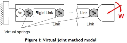
To understand the joint stiffness model, an algebraic analysis was done. To understand the fundamental derivation of the VJM technique, consider equations (1) to (3). Equation (1) defines the geometrical representation of the robot architecture; equation (2) describes the static equilibrium conditions (assuming no load); and equation (3) is representative of Hooke's law, describing the linear elasticity of the joints.
where δt represents the measured six-dimensional displacement and orientation vector (equation (4)) of the end effector, and a is the measured six-dimensional wrench vector of forces and moments (equation (5)).

J is the 6xn matrix, where n signifies the number of joints. δO represents the deflections in the virtual joint coordinate space owing to the loadings w. t represents the six-dimensional actuated torques in the elastic joints. Finally, Kg. reflects a diagonal 6xn matrix of the ith joint stiffness value.
The preliminary equations (1), (2) and (3) represent transitional equations to reach the Cartesian stiffness matrix Kc. The Kcmatrix defines the relationship between the translational and the rotational displacement of the end-effector in Cartesian space and the static forces and torques responsible for the transition, and is defined in equation (6):

Differentiating the actuated torques shown in equation (3) with respect to the six-dimensional joint coordinates yields the robot Cartesian stiffness matrix Kcas shown in equation (7):

Identifying dexterous zones and solving equation (7) within these zones simplifies the Cartesian model because the non-linear complimentary stiffness matrix Kxis negligible in regard to Kg. The simplified Cartesian stiffness matrix now becomes:

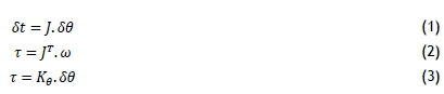
After algebraic manipulation of equations (1) to (3) and (6), a linear model describing the end-effector deflection owing to the applied wrench w is presented in equation (9), which formed the central basis of the VJM model technique. The complexity of the calculated deflection matrix shown in equation (9) is dependent on the number of DOF of the robot. The greater n is, the greater the computational effort and expense. The joint compliance variable K0-1represents the inverse of the joint stiffness matrix. The compliance of a robot signifies its degree of flexibility.

The compliance variable K0 1in equation (9) is denoted as matrix x, and is defined as:
where xjis the jth component of vector x for an n-DOF system:
To develop a linear model to evaluate the estimated joint stiffness K0, matrix x needs to be isolated from St. By isolating x, St can be transformed into matrix A, as shown in equation (10). The transformation process of St to matrix A defines the forces in joint space based on the forces applied in end-effector space w. In other words, the application of the Jacobian matrix in matrix A (equation (12)) defines the relationship between the applied end-effector forces and the resultant torques required by the robot's joints to support these forces. The size of the matrix is nxn, where n represents the number of DOF. The product of x and A evaluates back to δt (equation (11)).
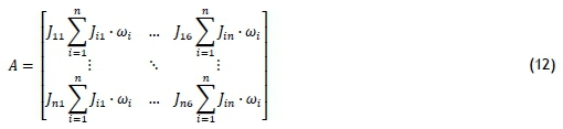
The product of matrix A and the joint compliances can now be represented in terms of the measured end-effector displacement, δt, as follows in equation (13):

For better accuracy of the VJM technique, it is required that multiple tests be performed. If i tests are performed, let Birepresent the A matrix and ci the δd matrix, such that equation (13) now becomes:

where:
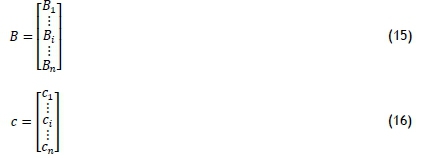
When the linear-equation system shown by equation (14) is overdetermined (n > 1), matrix B and matrix c become rectangular. Matrices of this nature can be solved using the Moore-Penrose pseudo inverse technique shown by equation (17):

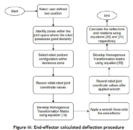
Consequently, several tests can be performed using this approach to evaluate the joint stiffness values. The end-effector deflections and rotations at each pose can be analysed through the homogeneous transformation matrix (HTM). The HTM is developed using the Denavit Hartenberg convention by attaching frames to the links of a spatial kinematic chain. This matrix is used to identify the position and orientation of the end-effector for an n-DOF robot. Each pose will have a unique HTM matrix. endefines the pose before the applied wrench, and £n' defines the pose after the applied wrench. The difference in homogeneous transformation between the two frames represents the deflection of the robot.
Let °T6and °T6' define the HTM from the base frame (e0 to £n) and from (e0to en') respectively. The two HTMs are obtained via the recorded end-effector coordinates before and after the applied wrench, and take the form:
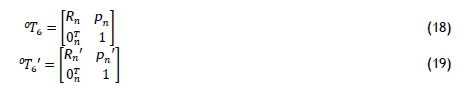
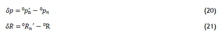
Equations (18) to (19) should be evaluated independently and in parallel with the above stiffness methodology (i.e., before and after each applied wrench w). Thereafter, the calculated translational displacement Sp and rotation SR of the end-effector can be expressed in e0as:
3.3 Procedure for determining the joint stiffness values
Applying the VJM within a robot's dexterous zones simplifies the stiffness formulation. The complementary stiffness matrix (Kx), which is a non-linear matrix, can be ignored during the calculation. For further understanding of (Kx), refer to [4, 29, 30].
SKMs are usually fixed to the ground or the ceiling, depending on the application. The workpiece can be positioned at any location within the robot's workspace envelope; it is usually fixed, and can be adjusted at various angles and distances away from the robot. The process of identifying postures of higher stiffness requires multiple points to be tested at various robot configurations. The stiffer points can be used to place the workpiece within the workspace for improved robot performance. Figure ii illustrates the procedure to evaluate the joint stiffnesses of the robot within a dexterous zone. The procedure to identify the calculated deflections of the robot end-effector is shown in Figure iii.
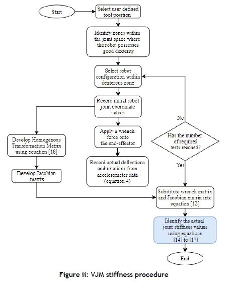
The first step records the initial robot joint coordinates at the user-defined point, as required to evaluate equation (18).
The second step evaluates the Jacobian matrix, derived from the robot's forward kinematic model. The Jacobian provides a detailed expression of the end-effector velocities derived from the robot's joint velocities as shown:
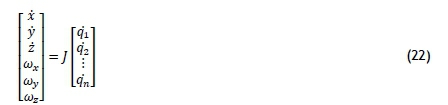
The Jacobian matrix has dimensions 6xn, where n is the number of joints. For a 6-DOF robot, the Jacobian will be of a size 6x6, where the upper three rows of the matrix represent the linear velocity and the lower three rows the angular velocity. The Jacobian matrix is configuration-dependent, and must be evaluated at points and configurations of interest.
The third step applies the wrench force to the end-effector. The wrench force is a measured variable. The wrench vector is of size 6 x 1, as shown in equation (6). The first three components represent the forces in the x, y, z directions, and the last three components are the moments about each axis. After the wrench force is applied, the joint coordinates of the end-effector are recorded to note the deflection from its initial position. These coordinates are used to evaluate equation (19). The translational and rotational displacements of the end-effector are determined by applying equations (20) an (21), about the user-defined point.
Once the Jacobian and wrench matrices have been derived, the fourth step evaluates matrix A, as shown in equation (12).
The fifth step records the measured deflection and orientation matrix St, as shown in equation (4). The translational and rotational deflections can be measured using a variety of sensors, including accelerometers, laser trackers, and other precision displacement sensors.
Finally, after developing the A and St matrices, the joint stiffness values for the configuration can be evaluated using equation (13). The result obtained from equation (13) is a square matrix. As previously mentioned, for better accuracy of the joint stiffness, several tests are needed, thus changing the matrix of size square to rectangular.
The Moore Penrose pseudo inverse technique, equation (17), can solve such non-square matrices. The result is joint stiffness in the robot with improved accuracy. The stiffness values can then be further analysed, based on various sources of error during the experimental procedure.
4 EXPERIMENTAL SET-UP AND TEST PROCEDURE
To illustrate the application of the above joint stiffness formulation using the VJM approach, the experimental procedure was developed in two stages. Stage one involved segmenting the robot's workspace and locating the robot's end-effector at multiple equidistant positions from the robot's base. The end-effector z-axis remained perpendicular to the ground for all non-dexterous tests. Stage two focused on the dexterity application and formulation developed by Mondragon [22]. Each stage involved the measured translational and rotational deflections. This was recorded using piezoelectric accelerometer modules attached to the end-effector in three dimensions (x, y, and z). The use of accelerometers for displacement measurement is much more compact, user-friendly, versatile, and cheaper than with laser trackers.
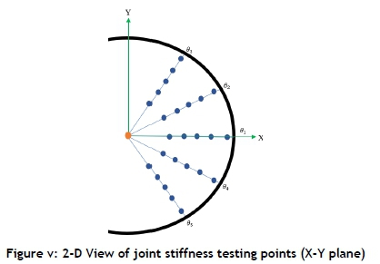
The workspace and singularities of the robot were identified before developing the testing layout shown in Figure iv. The testing points were defined using a cylindrical point cloud coordinate system, as shown in Figure iv. The point cloud was developed, starting at the robot's base. A point was developed at a radial distance (r) of 400 mm from the centre of the robot's base and 900 mm above the ground in the z direction. This point was incremented twice in the -0 (counterclockwise) direction and twice in the +0 (clockwise) direction by a constant 0.523599 radians (equivalent to 30°). This formed an arc at 400 mm (r1) comprising five testing points. Each of the five points along the arc was multiplied twice in the +z and -z directions by a constant vertical distance of 200 mm. This gave 25 testing points at radial distance r1. The five arcs, comprising 25 points, were repeated at a constant r of 200 mm from r1. As a result, the joint stiffness values were tested at r1 = 400 mm, r2 = 600mm, r3 = 800 mm, r4 = 1000 mm, and r5 = 1200 mm away from the centre of the robot's base, as seen in Figure iv. In total, the joint stiffness comprised 125 testing points.
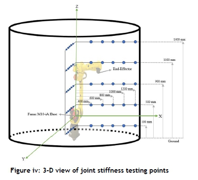
The point cloud was developed for three reasons. The first was to develop a trend analysis of the joint stiffnesses at multiple distances away from the robot's base and at multiple heights above the ground; the second reason was that the VJM requires multiple testing points to arrive at an accurate solution; and the third reason was to test the repeatability of the VJM modelling approach. The setup of points assisted in identifying optimal points and areas to perform manufacturing tasks.
The end-effector deflections and applied wrench force were displayed on a LabVIEW graphical user interface (GUI). The GUI indicated when the desired force range on the end-effector was reached. Each radial distance was individually post-processed. Given the complexity of the post-processing analysis, a separate GUI was developed, which applied the polynomial detrending bias removal technique applied in [31].
5 EXPERIMENTAL RESULTS
This section presents the experimental results. The dexterity and stiffness analysis procedures were programmed in Wolfram Mathematica. As previously mentioned, each test was accompanied by a 6-D wrench vector, a 6-D end-effector displacement vector, and an A matrix. To validate the measured deflections, calculated from equations (18) to (21), a linear regression model was developed. The regression analysis validated the measured results, as the deflection results and stiffness values were strongly correlated. Owing to the sample size of the tested point per radial distance, the R-squared number was sufficient to validate the measured deflection values. The sections that follow present the measured and calculated deflections and rotations, a table of estimated joint stiffness values, and the overall joint stiffnesses per radial distance. The trends per radial distance are analysed and discussed.
5.1 Joint stiffness identification
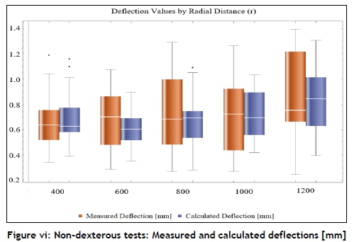
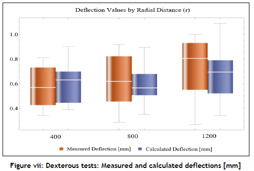
A wrench was applied to the end-effector at each test point shown in Figure iv. The robot end-effector was fixed in the -z direction at points along the radial distances (r1to rs) for all non-dexterous tests. On average, 20 tests were performed at each point. It was impossible to avoid singularities, especially during the dexterity analysis. Some outlying data can be seen in the deflection and rotational box-and-whisker charts. Figure vi and Figure vii provide a box-and-whisker plot with deflections experienced at each radial distance away from the robot' s base, for both non-dexterous and dexterous tests respectively.
The methodology used equations (18) to (21) to estimate the linear and angular displacements. The stiffness values were heavily dependent on the deflection and rotation values, and so a relationship between the measured and calculated deflections and rotations was required. The calculated deflections and rotations were validated by applying linear regression analysis to the calculated deflection values. The model was performed where the response (Y) was the measured deflections or rotations, and the predictor (X) was the calculated deflection or rotation. For the non-dexterous tests, the results showed a strong positive relationship, with R-squared values ranging between 69.9% and 79.7% for the deflection values, and between 63.3% and 68.3% for the rotation values, for all five radial distances (r1to rs). For the dexterous tests, the linear regression analysis had R-squared values ranging between 72.7% and 82.3% for the deflection, and between 65.7% and 71.1% for the rotation values for all three radial distances (r1,r3 and rs). This showed that the calculated model was robust and that the measured results were fit for the stiffness evaluation.
The testing regime within dexterous zones followed the same radial distance configuration as before; however, only radial distances r1, r3, and r5were analysed. A virtual cone-like structure formed by the intersection of the service region and the service sphere defined the dexterous zone. A total of nine dexterous zones were tested, with five unique postures per zone.
Figure vi and Figure vii portray the deflection box-and-whisker plot for both non-dexterous and dexterous tests respectively.
The overall trend in Figure vi for the non-dexterous test showed a gradual increase in deflections as the radial distance from the base increased. The maximum measured and calculated deflections for radial distance r1were 1.04 and 1.01 mm respectively, whereas for the dexterous tests, the measured and calculated deflections for radial distance r1were 0.81 and 0.9 respectively. The measured and calculated deflections for r3were 1.29 mm and 1.02 respectively for the non-dexterous tests, and 0.92 mm and 0.89 for the dexterous tests respectively. The greatest measured deflections for both tests were recorded at rs, with the deflection being 1.39 mm for the non-dexterous tests and 1.00 mm for the dexterous tests. The highest deflections for both tests were recorded in radial distance rs. The overall deflection performance during the dexterous tests shown in Figure vii improved by 46% compared with the non-dexterous tests. This improvement was owing to optimal postures about a point in space.
A further investigation was performed to understand the contribution of the robot's link deflections to the end-effector deflection. The link deflections were modelled during each test with the robot arm fully extended. The most significant contributions to the end-effector deflection, apart from the joints, were links two and four. By modelling the robot links as a square cross-sectional hollow beam, the link stiffnesses were estimated under various wrenches. The link deflections were measured during the maximum extension of the robot (r5 = 1200 mm). The results showed link 3 to be responsible for 0.9% of the end-effector displacement. Link 4, the second-longest of the links, was positioned nearly horizontal when the robot was fully extended, and owing to its cantilever effect, it contributed 11% to the end-effector displacement. Link 2, the longest link and the one furthest from the end-effector, contributed 9% to the end-effector displacement. These results highlighted a limitation of the VJM stiffness identification method, which assumes that the links are rigid.
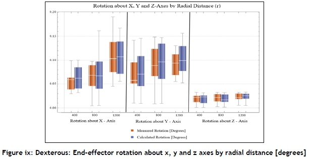
Figure viii and Figure ix provide the box-and-whisker plot of the rotation experienced about the x, y, and z axes owing to the applied torque wrench on the end-effector for both non-dexterous and dexterous tests respectively.
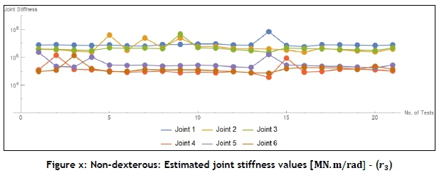
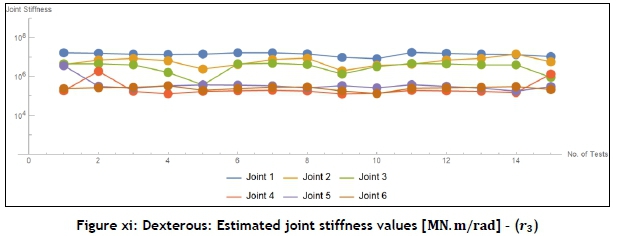
A similar trend to the linear deflections was noticed for the rotation measurements. For the x and y directions, the minimum end-effector rotations occurred closest to the robot base (r1), and increased as the end-effector moved further away from the robot's base. The z-axis recorded a similar rotation, with relatively small magnitudes over all radial distances. In Figure ix, the z-axis rotation remained relatively consistent in magnitude over r1,r2and r3. The rotations about the x, y, and z axes during the dexterous tests shown in Figure x displayed an improvement over the non-dexterous tests. The average rotation experienced about the x-axis improved by 16%, the y-axis improved by 42%, and the z-axis improved by 28%. Overall, the improvement in both the deflection and the rotation measurements within dexterous zones emphasised the structural improvements of the robot, which would lead to increased accuracy and repeatability. For demonstration purposes, the trendline of the non-dexterous and the dexterous joint stiffness values evaluated over 21 points for radial distance 3 are displayed in Figure x and Figure xi respectively.
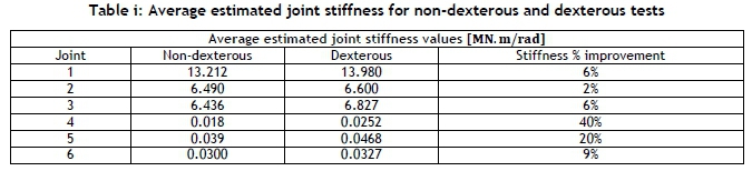
In Figure x the linearity of the trendline is fair, considering that tests were performed without taking dexterity into account. Figure xi shows the trend line for the joint stiffnesses during the dexterous tests. The linearity during the dexterous tests significantly improved on the non-dexterous tests. A similar trend line relationship with and without considering dexterity was found in [32]. Table i shows the average estimated joint stiffnesses recorded for all of the tests and the average joint stiffness percentage improvement.
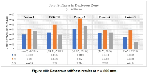
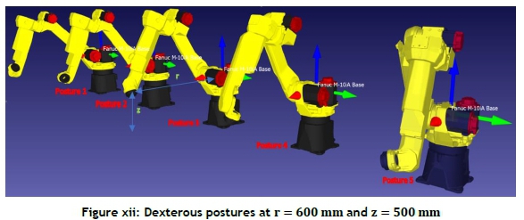
A stiffness analysis by posture was also investigated according to the dexterous ranges recorded by each radial distance. At r1, r3, and r5, the joint stiffnesses were measured within the dexterous zones. The joint stiffnesses were estimated by averaging all stiffness values by radial distance. For each posture, the end-effector - that is, joints 4, 5 and 6 - stiffness values are examined and displayed in Figure xiii (note that only r3results are presented, and the testing points and postures at z = 300 mm are displayed). Since joints 1 to 3 generally displayed high stiffnesses, the focus was more on the end-effector joints stiffnesses, since the applied wrench force directly impacted these joints.
The posture tests were performed about the mean ß and a values at each dexterous zone, then a further four tests at two equally distant ß and a values above and below the mean. This gave a total of five postures per dexterous zone, as shown in Figure xii.
As indicated in Figure xiii, postures 2 and 3 had the highest, and 1 and 5, the lowest ranges. The ß and a ranges were higher at r3= 800 mm, compared with r1= 400 mm. The maximum ß and a ranges at r1= 400 mm were -77.88° and 177.87°, respectively, compared with r = 600 mm, where the ranges for ß and a were 81.61° and 199.74° respectively. These results were expected, since there was a greater variety in the configurations that were possible towards the centre of the workspace, as opposed to when the links were contracted (r1= 400 mm) or when the robot was fully extended (r5= 1400 mm). The dexterous range was defined by ß[min, max] = {-44.70,36.91} and a[min, max] = {-129.81,69.93}. The stiffest postures were recorded between ß{min,max] = {-24.30,-3.895} and a{min,max] = {-79.88,-29.94}. Joints 5 and 6 had the highest stiffness at posture 2 of 0.0521 MN.m/rad and 0.0336 MN.m/rad, and posture 3 recorded the highest joint 6 stiffness of 0.0231 MN.m/rad.
Overall, for each dexterous zone, joint 5 emerged as the stiffest of the end-effector joints, followed by joint 6, and then 4. As the end-effector moved further away from the base of the robot (?\, r3and r5), the joint stiffness decreased. These results were consistent throughout the non-dexterous and dexterous tests. r1possessed the highest stiffness at postures 2 and 3, and was overall the stiffest compared with all other radial distances of points. Since adjacent postures had the highest joint stiffness, it can also be said that other configurations that lay within the range of postures 2 and 3 at r1and r3, and postures 2, 3 and 4 at r5mm, had high stiffnesses. Throughout each dexterous analysis, the stiffness was lowest at the extremities of the dexterous zones (positions 1 and 5). Although these values were lower at each distance (r1, r3and r5), the end-effector joint stiffness was improved when compared with the joint stiffness recorded during the non-dexterous tests.
To test the repeatability of the testing methodology, the errors and their implications were recorded. The errors for each stiffness variable shared a normally distributed relationship. The primary sources of errors that were reported during the experimental procedure included the sensitivity of the pCb accelerometers (±10% 100 mV/G or 10.2 mV/m/s2). The conversion to displacement approximated to a 0.1 mm difference between measured deflection and calculated deflection. The other sources of errors were the sensitivity of the S-type load cell (± 0.01 kg), the error in the servo-joints of the robot (± 0.05°), and finally, inconsistency in applying the wrench to the torque tool.
The errors recorded during the non-dexterous tests ranged between 1% and 32%. The errors during the dexterous tests ranged between 7% and 16%. The results that were recorded were acceptable, considering the testing instruments that were used. For the non-dexterous tests, five radial distances were tested; and for the dexterous tests, all three radial distances were tested. The overall joint stiffness decreased from r1to r5. This result was expected, since the robot entered a cantilever-like posture as the end-effector moved away from the robot's base.
The joint stiffness values increased for most joints in the dexterous zones. For r1- joint 1 stiffness was 18.31 x 10⁶ Nm/rad, whereas, in the non-dexterous zone, the stiffness recorded for r1was 16.84 x 10⁶ N.m/rad - a 9% improvement. Joint 2 (shoulder) increased by 11%, from 7.30x 10⁶ Nm/rad to 8.12x 10⁶ Nm/rad. In joints 3 and 4 (elbow), the stiffnesses increased by 5% and 32% respectively. Finally, the wrist (joints 5 and 6) increased in stiffness by 26% and 76% respectively. The results showed that the points closest to the robot's base had a high stiffness with smaller deflections. The overall joint stiffnesses gradually decreased with an increase in deflections as the end-effector moved away from the robot's base. Owing to the gradual elongation of the robot structure from r1to rs, the deflection increased in magnitude. For r3a similar joint stiffness improvement occurred; joints 4, 5 and 6 increased by 38%, 2% and 13% respectively. At rs, joints 4 and 5 increased drastically by 115% and 165% respectively, whereas joints 3 and 4 decreased by 9% and 18% respectively. The decrease in joint stiffness performance could be attributed to the unpredictability of the robot joint motion at r5, which influenced the joint settling times, which in turn affected the end-effectors actual joint coordinates.
Table i shows the average estimated joint stiffnesses recorded for all tests, and the average joint stiffness improvement as a percentage.
The robot's first joint, located on the base, recorded the highest stiffness with an average estimated joint stiffness value of 13.212 MN.m/rad during the non-dexterous tests and 13.980 MN.m/rad during the dexterous tests - a 6% increase. The base of the robot was heavily reinforced and firmly mounted, leading to the expected high stiffness. Joints 2 and 3 were both linked to the robot's base through link 2, and shared similar stiffness values. Joint 2 recorded an average joint stiffness improvement of 2%, and joint 3 increased by 6%. Joints 4, 5, and 6 were primarily responsible for the deflection of the robot. All three joint stiffnesses improved by 40%, 20%, and 9% respectively.
6 DISCUSSION OF RESULTS
This research explored the stiffness identification of an SKM at multiple postures about a user-defined point. The unique combination of the VJM and dexterity analysis was able to define the optimal areas and zones within the robot's reachable workspace that had high kinematical properties. The process of applying one-dimensional springs to model the joint stiffness, instead of modelling the complicated actuated joints of the robot, combined with the IK, provided a powerful tool to advance SKMs to more sophisticated manufacturing tasks. The use of accelerometers as a displacement measurement tool provided an easy and cost-effective setup, and was a reliable alternative to laser trackers. Two testing phases validated the above combination of the two techniques. The first phase involved a general joint stiffness identification of the robot at multiple equidistant points in the workspace. This phase was defined as non-dexterous testing, since the end-effector was fixed in the z-direction for all of the tests. The second phase, the dexterous tests, involved manoeuvring the end-effector about the same equidistant points, and demonstrating the effect that posture had on the mechanical rigidity of a robot.
The results displayed during the dexterous manipulation showed an improvement in the joint stiffness values. The IK approach determined the dexterous range by specifying the end-effector's coordinate position as the input. The dexterous formulation provided possible a and ß configurations that defined the dexterous space around a specific point in the robot's workspace. The geometrical nature of the method considered the link lengths of the robot, and was able to develop optimal configurations by orientating the links to minimise any excessive cantilever effect. The strain and backlash on the motors were therefore reduced. Consequently, the improved posture was able to withstand the wrench force effectively, resulting in improved overall stiffness.
To analyse the sensitivity of the results to measurement errors, all of the limitations governing each test were investigated. The use of accelerometers provided a cost-effective alternative to the laser tracking device. The process of converting the acceleration signals to displacement introduced errors. A least-squares polynomial fitting algorithm was applied to remove the DC bias involved in the integration of acceleration. Many studies have validated this algorithm as a feasible solution to correct the DC offsets [33, 34]. The method effectively offset the bias that was due to the integration of the raw acceleration values to displacement.
The shortfall in the VJM analysis was that the method assumed the links to be infinitely stiff and only the joints to be compliant. A further investigation was performed to analyse the effect of the link deflections on the overall end-effector deflection. The contributions were moderate; however, a more accurate stiffness model can be obtained.
The integration of a singularity analysis with the dexterous analysis would have promoted far more testing points, thereby improving the accuracy of the VJM approach. The contribution to environmental effects such as ground movement, wind, and electrical interferences would have skewed the results. It would therefore be prudent to perform such tests using accelerometers in an isolated vibration proof room, which would ensure accurate measurement readings.
An optimal robot configuration drastically improves the stiffness characteristics of the robot, as demonstrated by the testing in the dexterous zones. The dexterity analysis also demonstrated that, for dedicated tasks that are manufactured at the extremities of the robot, whether intentional or not, stiffer robot postures are still possible. Ultimately, the dexterity, VJM, and cost-effective testing regime, when combined, can guarantee the improved accuracy and repeatability of any manufacturing process, whether it be precision placement tasks in the electronics industry or machining in the automotive and aerospace industries.
7 CONCLUSION
The research conducted in this study aimed to improve SKM stiffness. The study proved that, although rigidity is attributed to accurate robot design, structure, and build quality, the identification of correct and optimal postures drastically affects a robot's stiffness. Defining the correct posture before a precision manufacturing task can improve a robot's performance. The adopted dexterity methodology enabled the location of optimal zones. The joint stiffness technique of applying virtual joints enabled an approximation of the joint stiffness of a robot. The discrepancies noted during the testing procedure were owing to the use of low-cost sensors. Nevertheless, the tools fabricated for this study, along with the data acquisition software and sensors, successfully met the overall aim and objective of the project.
In theory, the idea of replacing rotary joints with virtual joints drastically simplifies the model. Applying six-dimensional springs can optimise the model and provide more accurate joint stiffness values. This could be motivated for future research in this field. Ultimately, the study proves that optimal zones are accompanied by high stiffness, and that robot users can leverage improved robot postures to their advantage.
ACKNOWLEDGEMENTS
This work was supported by my supervisors, Professor Glen Bright and Dr Jared Padayachee, and the broader University of KwaZulu-Natal. I also thank Dr Mark Rawlins (Energy and Combustion Services) for his continuous support and guidance.
REFERENCES
[1] W. L. Stone, "The history of robotics," in Robotics and Automation Handbook,Thomas R. Kufess, ed: CRC Press, 2018, pp. 8-19. [ Links ]
[2] S. Caro, C. Dumas, S. Garnier, and B. Furet, "Workpiece placement optimization for machining operations with a KUKA KR270-2 robot," in 2013 IEEE International Conference on Robotics and Automation, 2013, pp. 2921 -2926. [ Links ]
[3] J. K. Salisbury, "Active stiffness control of a manipulator in cartesian coordinates," in 1980 19th iEEe Conference on Decision and Control including the Symposium on Adaptive Processes,,1980, pp. 95-100. [ Links ]
[4] A. Pashkevich, A. Klimchik, and D. Chablat, "Enhanced stiffness modeling of manipulators with passive joints," Mechanism and Machine Theory, vol. 46, pp. 662-679, 2011. [ Links ]
[5] U. Sudhakar and J. Srinvas, "A stiffness index prediction approach for 3-RPR planar parallel linkage," Interntional Journal of Engineering Research & Technology, vol. 2, pp. 2747-2751, 2013. [ Links ]
[6] Y. Guo, H. Dong, and Y. Ke, "Stiffness-oriented posture optimization in robotic machining applications," Robotics and Computer-Integrated Manufacturing, vol. 35, pp. 69-76, 2015. [ Links ]
[7] S. Sellami and V. M. Respall, "Geometric and stiffness modeling and design of calibration experiments for the 7 dof Serial Manipulator KUKA iiwa 14 R820," arXivpreprint arXiv:2006.06314, 2020. [ Links ]
[8] T. Cvitanic, V. Nguyen, and S. N. Melkote, "Pose optimization in robotic machining using static and dynamic stiffness models," Robotics and Computer-Integrated Manufacturing, vol. 66, p. 101992, 2020. [ Links ]
[9] J.-J. Park, B.-S. Kim, J.-B. Song, and H.-S. Kim, "Safe link mechanism based on nonlinear stiffness for collision safety," Mechanism and Machine Theory, vol. 43, no. 10, pp. 1332-1348, 2008. [ Links ]
[10] J. Angeles and F. C. Park, "Performance evaluation and design criteria," in Springer Handbook of Robotics, B. Siciliano and O. Khatib, Eds., Berlin: Springer, 2008, pp. 229-244. [ Links ]
[11] G. Alici and R. W. Daniel, "Static friction effects during hard-on-hard contact tasks and their implications for manipulator design: Communication," The International Journal of Robotics Research, vol. 13, no. 6 pp. 508-520, 1994. [ Links ]
[12] G. Alici and R. W. Daniel, "Robotic drilling under force control: Execution of a task," in Proceedings of the IEEE/RSJ/GI International Conference on Intelligent Robots and Systems '94'Advanced Robotic Systems and the Real World', IROS94, 1994, pp. 1618-1625. [ Links ]
[13] G. Alici and B. Shirinzadeh, "Enhanced stiffness modeling, identification and characterization for robot manipulators," IEEE Transactions on Robotics, vol. 24, no.4, pp. 554-564, August 2005. [ Links ]
[14] L. Sun and L. Fang, "Research on a novel robotic arm with non-backlash driving for industrial applications," in 2017 IEEE International Conference on Cybernetics and Intelligent Systems (CIS) and IEEE Conference on Robotics, Automation and Mechatronics (RAM), 2017, pp. 70-75. [ Links ]
[15] S. H. Kim, E. Nam, T. I. Ha, S.-H. Hwang, J. H. Lee, S.-H. Park, and B.K. Min, "Robotic machining: A review of recent progress," International Journal of Precision Engineering and Manufacturing, vol. 9, pp. 1-14, 2019. [ Links ]
[16] W. Owen, E. Croft, and B. Benhabib, "A multi-arm robotic system for optimal sculpting," Robotics and Computer-Integrated Manufacturing, vol. 24, no. 1, pp. 92-104, 2008. [ Links ]
[17] C. Chen, F. Peng, R. Yan, Y. Li, D. Wei, Z. Fan, X.Tang and Z.Zhu, "Stiffness performance index based posture and feed orientation optimization in robotic milling process," Robotics and Computer-Integrated Manufacturing, vol. 55, pp. 29-40, 2019. [ Links ]
[18] M. Xaud, "Modeling, control and electromechanical design of a modular lightweight manipulator for interaction and inspection tasks,", Ph.D. Dissertation, Alberto Luiz Coimbra Institute for Graduate Studies and Research in Engineering, Rio de Janeiro, 2016. [ Links ]
[19] H. Celikag, N. D. Sims, and E. Ozturk, "Chatter suppression in robotic milling by control of configuration dependent dynamics," Procedia CIRP, vol. 82, pp. 521-526, 2019. [ Links ]
[20] S. Mousavi, V. Gagnol, B. C. Bouzgarrou, and P. Ray, "Dynamic modeling and stability prediction in robotic machining," The International Journal of Advanced Manufacturing Technology, vol. 88, pp. 3053-3065, 2017. [ Links ]
[21] K. Abdel-Malek, W. Yu, and J. Yang, "Placement of robot manipulators to maximize dexterity," International Journal of Robotics and Automation, vol. 19, pp. 6-14, 2004. [ Links ]
[22] C. Mondragon, "Dynamics and motion of a six degree of freedom robot manipulator," , Ph.D. Dissertation, University of Saskatchewan, 2012. [ Links ]
[23] A. Klimchik, "Enhanced stiffness modeling of serial and parallel manipulators for robotic-based processing of high performance materials, Ph.D. Dissertation, " Ecole Centrale de Nantes (ECN); Ecole des Mines de Nantes, 2011. [ Links ]
[24] T. Pigoski, M. Griffis, and J. Duffy, "Stiffness mappings employing different frames of reference," Mechanism and Machine Theory, vol. 33, no. 6, pp. 825-838, 1998. [ Links ]
[25] F. Majou, C. Gosselin, P. Wenger, and D. Chablat, "Parametric stiffness analysis of the orthoglide," Mechanism and Machine Theory, vol. 42, no. 3, pp. 296-311, 2007. [ Links ]
[26] M. Hu, H. Wang, and X. Pan, "An extended stiffness model for 7 Dofs collaborative robots using the virtual joint method," in 2019 IEEE International Conference on Robotics and Biomimetics (ROBIO), 2019, pp. 1653-1658. [ Links ]
[27] A. Pashkevich, D. Chablat, and P. Wenger, "Stiffness analysis of overconstrained parallel manipulators," Mechanism and Machine Theory, vol. 44, no. 5, pp. 966-982, 2009. [ Links ]
[28] J. Knapczyk and M. Ryska, "Stiffness matrix analysis of six-revolute serial manipulator," Acta Mechanica et Automatica, vol. 6, no. 2, pp. 62-65, 2012. [ Links ]
Submitted by authors 7 Sep 2021
Accepted for publication 15 Nov 2021
Available online 14 Dec 2021
* Corresponding author: 213535641@stu.ukzn.ac.za

