


Services on Demand
Article
 English (pdf)
 Article in xml format
 Article references
Indicators

Related links
-
 Cited by Google
 -
 Similars in Google
Share

 Permalink
South African Journal of Industrial Engineering
On-line version ISSN 2224-7890
Print version ISSN 1012-277X
S. Afr. J. Ind. Eng. vol.32 n.4 Pretoria Dec. 2021
http://dx.doi.org/10.7166/32-4-2513
GENERAL ARTICLES
Welding of additive manufactured ALSi10mg: using laser welding in a vacuum for high quality weld seams - a new approach to welding LPBF manufactured ALSi10mg
A. SchwarzI, *; M. SchleserII; B. GerhardsIII; P. PopoolaIV; A. GebhardtV
IIwF GmbH - Institute for toolless fabrication, Germany. https://orcid.org/0000-0002-1520-0764
IIDepartment of Mechanical Engineering and Mechatronics, Aachen University of applied sciences, Germany. https://orcid.org/0000-0002-0260-3927
IIILaVa-X GmbH, Germany. https://orcid.org/0000-0003-0068-1136
IVDepartment of Chemical, Metallurgical and Materials Engineering, Faculty of Engineering and the Built Environment, Tshwane University of Technology, Pretoria, South Africa. https://orcid.org/0000-0003-4447-8551
VDepartment of Mechanical Engineering and Mechatronics, Aachen University of Applied sciences, Germany. https://orcid.org/0000-0002-8181-1897
ABSTRACT
Metal additive manufacturing has evolved to a manufacturing process used in different industries. Especially in highly complex applications with small batches, such as aerospace or tooling, laser powder bed fusion (LPBF) has become established. But one of its major limitations is the size of the build chamber, which is limited to around 800 x 400 x 500 mm for the largest machine that is currently available. One solution to overcome this size limitation is to weld additive manufactured parts. While it has been proven for different materials that conventional welding processes can be applied to LPBF manufactured parts, the resulting weld seam quality for AlSi10Mg is still insufficient. By using laser welding in a vacuum, which is a newly developed and highly efficient laser welding process, the quality of the weld seams, especially in terms of porosity, can be improved. This technology is used to produce weld seams that are then tested for their mechanical properties. Finally, a solution for combining LPBF parts with conventional aluminium alloys is presented.
OPSOMMING
Metaal toevoegingsvervaardiging het ontwikkel tot 'n vervaardigingstegniek wat in verskeie bedrywe gebruik word. Dit is veral die geval in baie komplekse toepassings met 'n klein produksielot soos in die lugvaart of gereedskapstuk vervaardigingsbedrywe. Een van die ernstige beperkings van laser poeierbedfusie, een van die gevestigde vervaardigingstegnieke, is die grootte van die kamer - die grootste masjien is beperk tot 'n kamer van 800 x 400 x 500 mm. Een manier om hierdie probleem op te los, is om toevoegingsvervaardigde onderdele aan mekaar vas te sweis. Alhoewel daar al bewys is dat konvensionele sweistegnieke geskik is vir laser poeierbedfusie vervaardigde onderdele, is die sweisgehalte vir AlSi10Mg onvoldoende. 'n Nuwe sweistegniek, naamlik lasersweis binne 'n vakuum, verbeter die gehalte van sweisnate, veral die porositeit. Die sweisnate wat met hierdie sweistegniek gevorm word, word in hierdie artikel getoets om hul meganiese eienskappe te bepaal. Daar word dan n oplossing om laser poeierbedfusie vervaardigde onderdele aan mekaar vas te sweis voorgehou.
1 INTRODUCTION
Metal additive manufacturing - and especially the laser powder bed fusion process (LPBF) - has become established in the industry as a commonly used manufacturing process for high complex parts. Owing to its layer-wise manufacturing process, if offers a design freedom that could not be achieved by any other manufacturing process, such as turning or lathing. But this freedom in design is not just a possibility offered by the process: it is required if the LPBF processes are to be efficient. Only by using the advantages of the additive production can it compete with other manufacturing processes. LPBF is used in a wide range of different industries, including automotive, aerospace, and tooling.
One of the major limitations of additive manufacturing in general, but especially for LPBF process, is the size of the build chamber. The last few years have shown that manufacturers follow the demands of the industry by developing and introducing larger LPBF machines.
Another approach to solving the size limitation of LPBF machines is the use of welding. By combining smaller LPBF parts with semi-finished products, the disadvantage of the low productivity of the LPBF machines could be avoided. But the combination of two LPBF parts to create large, complex components is also possible.
2 STATE OF THE ART
As stated in the introduction, one major drawback of today's processes is the limited size of the build chamber. Different machine manufacturers try to solve this issue by introducing larger machines. One machine manufacturer that uses this strategy is Concept Laser, which currently makes the largest commercially available machine on the market, the XLine 2000R [1]. But the company is planning even larger machines, as shown by its project A.T.L.A.S., which offers a build size of 1100 x 1100 x 300 mm [2]. But new competitors, such as Adria from Portugal, are also introducing larger machines for the LPBF process [3]. However, the larger build chamber sizes not only offer the advantage of a larger build chamber: they also introduce various drawbacks:
■ Higher costs for material storage
■ Longer process times
■ Higher risks of failures
■ Very high hourly costs for the machines
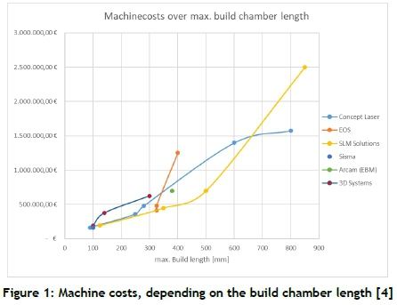
Not only are the running costs of the machines increasing, but the investment costs for the machine itself are growing exponentially along with the increasing size of the build chamber. Figure 1 shows the costs of different machines, depending on their build chamber size.
One method to overcome this limitation is to combine LPBF with welding. With welding there are two possibilities. The first is for the additive manufactured part to be joined with another additive manufactured one; the second is to join the additive manufactured part with a conventional manufactured part. If the second option is used, a solution to another drawback of the current LPBF systems is offered: limited productivity. If the LPBF process is compared with other manufacturing processes that are used for mass production, it is slower. In joining additive manufactured parts with conventional parts, only a small LPBF part is produced and then joined with conventional semi-finished products, such as tubes or profiles. This approach has been used, for example, by EDAG, Siemens, and Concept Laser [5]. It can be altered if it is used for aluminium in combination with laser welding in a vacuum. Besides the size limitations of the LPBF process chamber, the size of the vacuum chamber of the available LaVaCells is also limited. If the laser welding in a vacuum process is used for the welding of an intermediate part, a joint with conventional material is possible. Basically, the connection between the LPBF part and the conventional part will consist of the LPBF part being welded to an intermediate part made from a good weldable conventional aluminium alloy with laser welding in a vacuum, and then welded to the main component by a conventional welding process such as TIG- or MIG-welding.
For this approach to the welding to work, the material is crucial. For the material 316L different publications proved the weldability of parts made with LPBF - for example, Laitinen [6], Järvinen [7], and Casalino et al. [8]. For titanium too, different publications showed that the material is weldable using the LPBF process. But for both materials, adjustments to the welding parameters of conventional material were necessary to achieve an adequate sufficient weld seam quality.
For the additive manufactured aluminium alloy AlSi10Mg, no sufficient solution with conventional welding processes such as TIG-welding has been found so far [9]. Similar to the expectations and knowledge from welding die-cast aluminium parts, hydrogen pores cause high porosities in the weld seam, as shown in Figure 2. Emmelmann et al. [9] showed that the weldability of LPBF-manufactured AlSi10Mg is even worse than that of die-cast parts.
The reason for the worse weldability of additive manufactured AlSi10Mg is assumed to be the presence of hydrogen in the base material. The powder, which is the base material for the LPBF process, offers a large surface area and therefore the possibility for oxidation. These oxides are then melted during the LPBF processing, and hydrogen is introduced into the base material. During the subsequent welding process, the included hydrogen results in visible pores in the cross-section. Gref has showed that the lowest possible porosity occurs when then amount of molten base material is reduced [10].
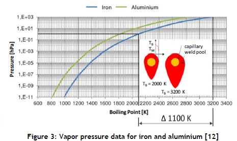
In previous research the possibility of producing high-quality weld seams on additive manufactured AlSi10Mg is shown when laser welding in a vacuum is used [11]. In so doing, the amount of molten base material is reduced. As Gref [10] mentioned, reducing the molten base material is the most efficient way to reduce the porosity in the weld seam. The difference in the approach is the physical effect that is used to achieve the reduction of molten base material. By reducing the environmental pressure, the boiling point of a material is affected, while the melting temperature remains nearly constant. For aluminium, the boiling point is reduced by 1000 K if the pressure is reduced by 1 mbar, as shown in Figure 3.
When the laser welding is carried out in keyhole mode, the temperature difference between the keyhole in which the material is evaporating and the surrounding base material is reduced, and so is the amount of base material that is molten. By using this effect, the amount of hydrogen that is released from the base material is reduced, and so is the number of pores in the weld seam. While the previous research on laser welding in a vacuum for additive manufactured AlSi10Mg focused on the use of beam oscillation, in the analyses presented in this paper, multiple passes are used to decrease the porosity of the weld seams. After the analyses of the welding parameters, specimens for tensile testing are produced, welded, and tested. The results are then compared with the values for additive manufactured AlSi10Mg, as stated by the VDI 3405 - part 2.1 [13].
3 EXPERIMENTAL SETUP
For the experimental setup, two parts had to be separated: the LPBF process and the laser welding in a vacuum process.
3.1 LPBF - Concept Laser XLine 2000R
To produce the test specimens, the Concept Laser XLine 2000R, located at the Aachen University of Applied Sciences, was used. It offered a build chamber size of 400 x 800 x 500 mm, and used two 1 kW fibre lasers that each covered a scanning field of 400 x 400 mm.
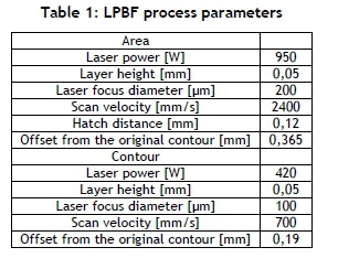
To reduce the thermal tensions that result from the LPBF process, two methods were used. During the production process, the build plate was heated to 200°C. At this temperature, a stress-relief annealing of the AlSi10Mg takes place, and the tensions are reduced [14]. The second approach was defined by the orientation of the specimen. By reducing the cross-section that was melted in each layer, the scan vectors were shortened, and therefore the resulting tensions were reduced. The parameters that were used for the LPBF process can be found in Table 1 below.
If the specimen manufactured by the LPBF process were used without further post-processing, its surface roughness would result in welding gaps for the laser beam that were too large. Therefore, a milling of the groove faces needs to take place to reduce the welding gap to a minimum.
3.2 Laser welding in a vacuum
For the laser welding in a vacuum, the LaVaCell 260 from the Aachen-based company LaVaX was used. It offers a high-efficient laser welding process owing to the reduced environmental pressure. Using an intelliSCAN 30 laser scanner from ScanLab in combination with a rotary table, simultaneous movements are possible - for example, a rotation of the part and a circular oscillation of the laser beam. This offers the possibility of using different beam oscillation figures in a simple way. The SPI redPOWER® Qube with a maximum laser beam power of 2 kW and a fibre diameter of 25 um, in combination with an f-theta lens, results in a 95.5 urn spot.
3.3 Materials
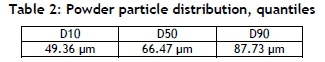
Two different aluminium alloys were used in this study. The first alloy was the powder material AlSi10Mg(a) for the LPBF process. A grain size distribution of between 45 μm and 75 μm was used. The quantiles of the powder distribution are shown in Table 2.
According to the DIN EN 1706, the chemical composition of the material is given by Table 3.
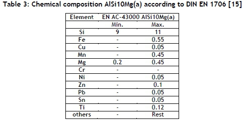
The AlSi10Mg(a) is generally considered an excellent weldable material, as in this comment: "The weldability of die castings depends on the amount of gas trapped and is insufficient in most cases. Values from B to C can be achieved with certain casting processes" [15]. As in the die casting process, during the LPBF process gas is trapped in the manufactured components, resulting in a degradation of the weldability of the manufactured parts, as shown in the literature review.
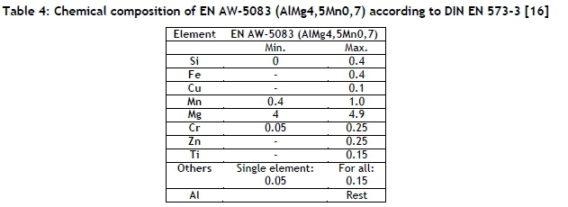
The second material used for the tests was the EN AW-5083 (AlMg4,5Mn0,7) aluminium alloy. EN AW-5083 is a non-age-hardenable (naturally hard) alloy, and can therefore be used directly or formed after homogenisation. Heat treatment to increase strength is not possible. Owing to its very good resistance to corrosion, this alloy is mainly used in shipbuilding and the chemical industry. Its chemical composition can be found in Table 4 below. As the EN AW-5083 is generally considered to be highly weldable, it can be used as an intermediate part to establish weld joints with conventional welding processes such as TIG- or MAG-welding.
3.4 Procedure
For the weld in tests, the specimens were placed without clamping in the build chamber of the LaVaCell. The butt welds were done while the specimens were clamped and pressed against each other. By doing so, it was possible to create a technical zero gap, which was necessary for the welding with the laser, although the laser beam oscillation offered a limited possibility for gap bridging. The specimens for the tensile testing were milled from the welded aluminium sheets.
The welding of the demonstration sample for joining an additive with a conventional manufactured part was clamped in the rotary device. While the rotary device was turning, the laser beam performed an oscillating movement to create the weld seam.
4 RESULTS AND DISCUSSION
As the earlier literature review showed, conventional welding methods are not applicable for the welding of additive manufactured AlSi10Mg. But by applying the welding process in a low-pressure atmosphere, different partly interdependent effects could be expected.
■ Owing to the smaller volume that was melted by the laser, the amount of material from which hydrogen could be released into the weld pool, and thus the amount of hydrogen available for pore formation, would be reduced, and so the number of pores should be reduced.
■ The difference in pressure between the pores and the atmosphere was higher than in a standard atmosphere, which should improve the outgassing of the pores.
Although the flexibility of conventional welding processes was lost, the laser welding in a vacuum could have been a sufficient solution to porosity in the weld seams. The idea was to first join the additive manufactured part with a conventionally manufactured part by laser welding in a vacuum. The conventionally manufactured part, which had to be made from good weldable material, was used as an intermediate part for the second process step. In the second step, TIG-welding was used to join two conventionally manufactured aluminium parts together. This offered the possibility to weld additive manufactured parts made from AlSi10Mg on to larger structures that would not fit into the vacuum chamber for laser welding.
The weld tests were carried out with multiple repetitions of the scanning. It was assumed that, with multiple remelting of the same area, the gas inclusions had time for outgassing. The tests with laser welding in a vacuum were split into two tests. First, the material behaviour of the additive manufactured parts in the laser vacuum welding process was tested; thus the pore formation of the parts was analysed by weld-in tests. The second test included the joining of two additive manufactured parts.
4.1 Multiple repetitions of the welding
For the first tests of the material behaviour, melt tracks were applied on the surface of the specimen. The following parameters were used for the weld in these tests:
■ Pressure: 15.5 mbar
■ Laser power: 500 W
■ Welding velocity: 10 mm/s
■ Inert gas: 5 l/min
The tracks were welded with two, four, and six repetitions to test whether pores occurred in the weld seam. If they did, it should have been possible, by repeated welding, to remelt the material and give the pores a chance to diffuse out of the liquid material.
Figure 4 below shows the top of the three weld tracks. As can be seen, the beginning and the end of the weld seam were broader than the middle part. This was a result of the welding without ramping up the laser power or using an extended scanning track to accelerate the laser to a constant speed before the welding process started. But the surfaces of the welds with two and four repetitions were very flat and smooth. The surface of the weld seam that was scanned six times seemed to sag in comparison.
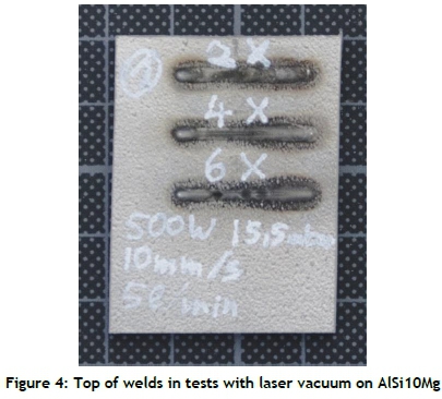
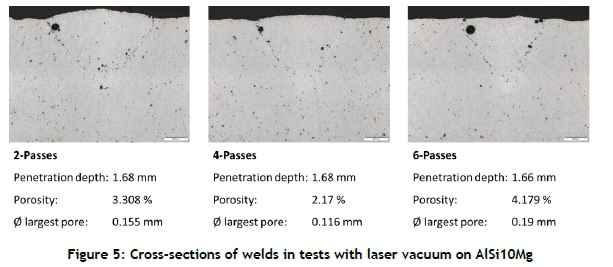
After the analysis of the surface of the weld seams, cross-sections were analysed, taken from the middle of the weld seams to avoid the influence of the broader beginning and end. The results of these tests are shown in Figure 5.
As can be seen, pores occurred only on the boundary between the weld seam and the base material. With an increased number of repetitions, the density of the weld could be only slightly increased. But, as a result of the higher energy input, the top of the weld's seam was flatter. The weld seam with four repetitions of welding showed the best results in respect of porosity. If six repetitions were used, the porosity increased, and a pore began to grow at the side of the weld seam.
After the results of the test welding, the parameters were used to join two additively manufactured parts together. The welding parameters that were used were the same as those used for the welds in the tests. Figure 6 shows the surfaces of the joint welds.
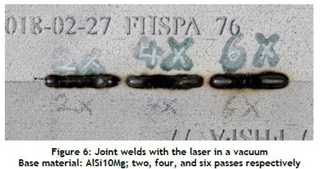
It is evident that strong oxidation took place during the welding process. As the chamber was evacuated to a pressure of 15.5 mbar, the oxygen for the oxidation must have been present in the porosity of the additive manufactured specimens. This strengthens the assumption from the tests with TIG-welding that the pores that were present in the weld seam were caused by gases that were introduced into the specimens during the manufacturing process. Although the surfaces were strongly oxidised, the cross-sections were analysed to investigate the pore formation in relation the welding passes. The results are shown in Figure 7.
The specimen with two welding passes showed a large pore directly under the surface of the weld, and smaller pores were present at the boundary of the weld seam and the base material. The top of the weld showed a very flat surface, with no sagging of the seam. The welding with four passes had a reduced porosity at the boundary of the weld seam, while the large pore in the middle of the seam was still present. The weld with six passes showed only minor differences from the previous results: the porosity could not be reduced further, and the pore in the middle of the seam was also still present.
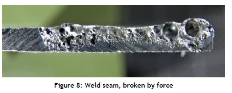
While the weld seams on the surface of the specimens were dense, the joining of two specimens still showed pores in the cross-section of the weld seam. This led to the conclusion that multiple passes were not sufficient to produce pore-free weld seams. Instead, a continuous movement of the laser beam had to be used to enable the outgassing of the pores, as described by Fetzer et al. [17]. In addition, not ramping up the laser power and the welding speed, which caused the broadening of the weld seam, resulted in a high number of pores at the beginning and the end of the weld seam, as shown in Figure 8. To avoid these pores, further investigations must focus on the influence of the pressure, and thus on the boiling point of the material; but this did not form part of this study.
4.2 Tensile testing
Based on the previous findings, specimens for tensile testing of the laser in a vacuum welding process were produced. For these tensile tests, metal sheets with a size of 200 x 50 x 3 mm with a standing orientation in the LPBF process were welded. The welding parameters are listed below:
■ Pressure: 24 mbar
■ Laser power: 500 W
■ Welding velocity: 5 mm/s
■ Inert gas: 15 l/min
■ Beam oscillation: Circular, 200 Hz
■ Oscillation amplitude: 0.1 mm
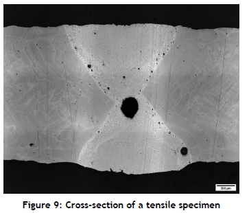
That list shows that a circular beam oscillation was added to the welding movement. Based on the study of Fetzer et al. [17], this oscillation strategy offers the lowest number of pores in the weld seam. A counter-layer is needed, as the penetration depth of the laser welding process is limited to 1.6 - 1.7 mm.
From Figure 9, it can be seen that the largest pore occurred in the overlapping area between the first and the counter-layer, and smaller pores could be found at the fusion line.
For the tensile testing, specimens were milled from the already welded material. The testing was done according to standard DIN EN ISO 6892-1 [18] on a Zwick SmartPro with a maximum force of 100 kN. The results of the tensile testing are shown in Figure 10 and Table 5.
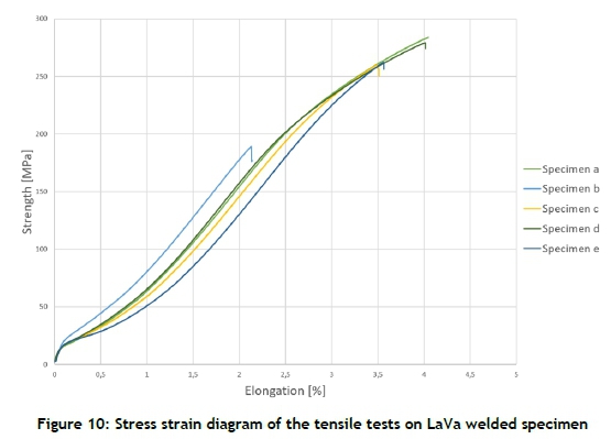
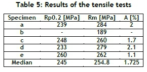
If the values from Table 5 are compared with the range of values given by the VDI 3405 - part 2.1 [13], it can be seen that the tensile strength was reduced by the pores in the weld seam (median of the tensile tests: 254.8 MPa; VDI: 372 - 473 MPa). However, the yield strength was on the level of the VDI standard (median of the tensile tests: 245 MPa; VDI: 239 - 292 MPa). This could be explained by the residual pores in the weld seam, which limited the tensile strength. In Figure 11, which shows the tensile specimens after the testing, the area of the break is visible.
All of the specimens were broken in the weld seam and not in the base material. Therefore, it was necessary to carry out additional welding tests to avoid the pores between the first layer and the counter-layer. Two different strategies could be used for this. Either the weld seam needed to be ground after the welding of the first layer, or a longer cool time had to be allowed for after the first layer.
For the tests shown in this study, the first layer was welded and then the specimens were flipped, and the counter-layer was welded. If pores on the base of the first layer occurred, these pores influenced the welding of the counter-layer. To avoid that disturbance, for conventional aluminium welding, grinding the weld seam base is mandatory. Normally the vacuum atmosphere would prevent the oxides on the root of the weld; however, owing to residuals in the base material, the oxide layer could still occur. As grinding is not possible in a vacuum, it would be necessary to remove the specimens from the vacuum, thus creating a further process step. Also, the extension of the cooling time after the first layer could have an influence, as the temperature of the base material is higher after the first welded layer, which causes lower heat conduction into the base material.
4.3 Joining an AM part with a conventional part
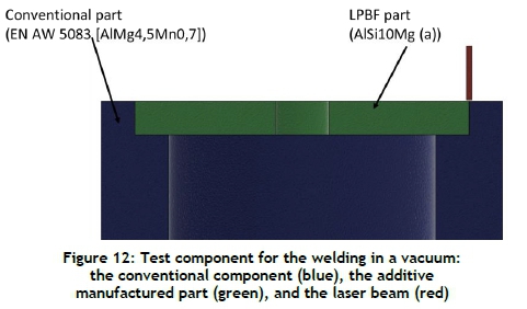
To illustrate the idea of an intermediate part, a joint between an additive manufactured part and a conventionally manufactured part was welded.
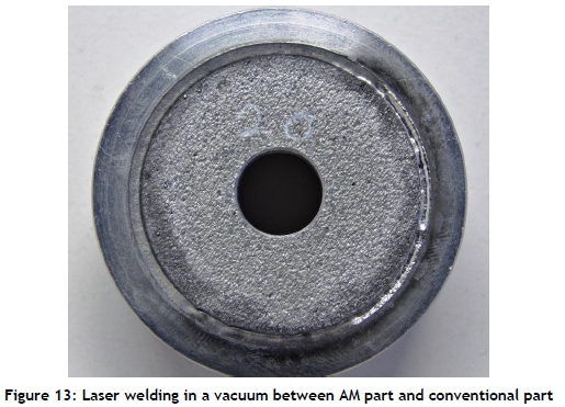
The part was a circular symmetric component with an axial weld, so that the additive manufactured part was the cover. For the welding, the rotary table in the vacuum welding machine was used to create the linear movement, while the laser scanner added the beam oscillation. The basic design of the test geometry is shown in Figure 12.
To increase the penetration depth of the laser, the pressure in the chamber was reduced to only 7 mbar. This affected the boiling point of the material and led to a reduced evaporation temperature. The difficulty here was to control the fumes from the welding process, as a reduction in the pressure led to more fumes from the welding process, which influenced the absorption of the laser and also potentially covered the entry glass of the vacuum chamber.
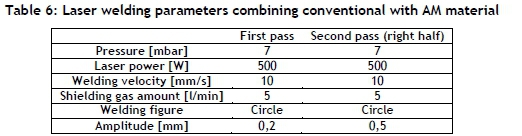
The top view of the weld seam is documented in Figure 13. It can be seen that the weld was not done in a single process, and the parameters were changed during the weld. The right side was glossier than the left side. This was due to a second welding pass on the right. For this second pass, the parameters of the laser welding process were changed, and the penetration depth of the weld was increased. The parameters that were used are shown in Table 6.
The specimen was cut in half and then embedded to analyse the cross-sections on both sides of the weld. The left side of the cross-section is shown in Figure 14, and the right side in Figure 15.
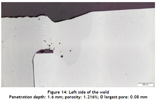
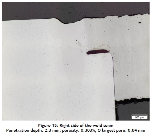
As a result of the second pass with an overlaying circular movement of the scanner system, it is obvious that the depth of penetration was increased to 2.3 mm and that the porosity was reduced to 0.303%. This confirmed the theory that, with an increased time for the diffusion of the gas bubbles and multiple interactions between the laser beam and the weld pool, the porosity of the weld was decreased. This process was supported by the reduced atmospheric pressure in the vacuum chamber.
The test showed that a high-quality weld seam with a reduced porosity is possible using laser welding in a vacuum. With the use of an oscillating beam, the outgassing was improved and the penetration depth was increased. The key parameters for a successful laser welding process in a vacuum are the combination of beam movement and environmental pressure.
5 CONCLUSION AND OUTLOOK
This research revealed the possibility of welding LPBF manufactured AlSi10Mg with laser welding in a vacuum. While most conventional welding processes produce a high porosity in the weld seam, with laser welding in a vacuum it is possible to produce high-quality weld seams with low porosity.
It was found that multiple passes on the weld seam do not necessarily improve the quality of weld seams in respect of porosity. Therefore, the hypothesis that multiple weld passes have an influence on the porosity of the parts is not sufficient. The beam oscillation has a greater influence during the welding process. If a continuous movement of the laser beam is achieved without stopping when changing direction, the porosity of the weld seam can be reduced. A combination of multiple passes with an oscillating beam can then be used to increase the weld depth.
In the case of the combination of a conventionally manufactured part and an additively manufactured part, multiple passes in combination with a beam oscillation increased the weld seam quality. By using this combination, it was possible to reduce the porosity from 1.216% to only 0.303%. At the same time the weld depth increased from 1.6 mm to 2.3 mm.
The combination of a beam oscillation with multiple passes of the laser seams to be the best way to decrease porosity in weld seams while at the same time increasing the weld depth.
Further research needs to be carried out to test whether the combination of beam oscillation with multiple passes could also be used for double-sided weld seams, in which the pore is located in the middle between the two weld seams.
ACKNOWLEDGEMENTS
The Concept Laser XLine2000R machine at the Aachen University of Applied Sciences was funded by the Federal Ministry of Education and Research as part of the funding of strategic investments at universities of applied sciences (FHInvest).

REFERENCES
[1] Fraunhofer Institute for Laser Technology (ILT). 2012. LaserCUSING in an XXL format for the carmaker Daimler. Aachen. [ Links ]
[2] 2017. GE Additive unveils first BETA machine from its Project Atlas program. Lichtenfels:. [ Links ]
[3] EuropaWire PR Editors. 2019. Breakthrough on laser powder bed fusion technology brings effective production of larger components closer to mainstream. 29 May 2019. [ Links ]
[4] Wohlers, T. T. & Caffrey, T. 2018. Wohlers Report 2018: 3D printing and additive manufacturing state of the industry annual worldwide progress report. Fort Collins, COL: Wohlers Associates 2018. [ Links ]
[5] Ohlsen, J., Herzog, F., Raso, S. & Emmelmann, C. 2015. Funktionsintegrierte, bionisch optimierte fahrzeugleichtbaustruktur in flexibler fertigung. ATZ, 10, pp. 54-58. [ Links ]
[6] Laitinen, V.P. 2015. Weldability of powder bed fusion fabricated stainless steel 316l sheets to cold rolled sheet metal. Master's thesis, Lahti University of Technology, Finland. [ Links ]
[7] Järvinen, J.-P. 2014. Welding of additively manufactured stainless steel parts: Comparative study between sheet metal and selective laser melted parts. Master's thesis, Lappeenranta University of Technology, Finland. [ Links ]
[8] Casalino, G., Campanelli, S. L. & Ludovico, A. D. 2013. Laser-arc hybrid welding of wrought to selective laser molten stainless steel. The International Journal of Advanced Manufacturing Technology, 68(1-4), pp. 209-216. [ Links ]
[9] Emmelmann, C. & Beckmann, F. 2015. Hybrid lightweight design by laser additive manufacturing and laser welding processes. Lasers in Manufacturing Conference, 2015. [ Links ]
[10] Gref, W. 2005. Laserstrahlschweißen von aluminiumwerkstoffen mit der Fokusmatrixtechnik. Universität Stuttgart Dissertation, Stuttgart. [ Links ]
[11] Gerhards, B., Schleser, M., Otten, C., Schwarz, A. & Gebhardt, A. 2019. Innovative laser beam joining technology for additive manufactured parts. Conference Proceedings: 72nd IIW Annual Assembly and International Conference, Bratislava, pp. 1-8. [ Links ]
[12] Honig, R. E. & Kramer, D. A. 1969. Vapor pressure data for the solid and liquid elements. RCA Review, 30, pp. 285305. [ Links ]
[13] Richtlinie 3405 - Blatt 2.1. 2020. Additive fertigungsverfahren - Pulverbettbasiertes schmelzen von metall mittels laserstrahl (PBF-LB/M) - Materialkenndatenblatt aluminiumlegierung AlSi10Mg. Available at: https://www.beuth.de/de/technische-regel/vdi-3405-blatt-2-1/326385793 [ Links ]
[14] Buchbinder, D., Schilling, G., Meiners, W., Pirch, N. & Wissenbach, K. 2011. Untersuchung zur reduzierung des verzugs durch vorwärmung bei der herstellung von aluminiumbauteilen mittels SLM. RTejournal - Forum für Rapid Technologie, 8, p.15. [ Links ]
[15] Norm DIN EN 1706:2013-12. Aluminium and aluminium alloys: Castings: Chemical composition and mechanical properties. Beuth Publishing House. [ Links ]
[16] DIN EN 573-3:2019-10. 2019. Aluminium und aluminiumlegierungen: Chemische zusammensetzung und form von Halbzeug_- Teil_3: Chemische zusammensetzung und erzeugnisformen. Deutsche Fassung EN_573-3:2019. [ Links ]
[17] Fetzer, F., Sommer, M., Weber, R., Weberpals, J.-P. & Graf, T. 2018. Reduction of pores by means of laser beam oscillation during remote welding of AlMgSi. Optics and Lasers in Engineering, 108(2018), pp. 68-77. [ Links ]
[18] DIN EN ISO 6892-1:2020-06. Metallische Werkstoffe - Zugversuch - Teil_1: Prüfverfahren bei Raumtemperatur (ISO_6892-1:2019). Deutsche Fassung EN_ISO_6892-1:2019. [ Links ]
Submitted by authors 29 Mar 2021
Accepted for publication 19 Oct 2021
Available online 14 Dec 2021
* Corresponding author armin.d@unhas.ac.id

