


Services on Demand
Article
 English (pdf)
 Article in xml format
 Article references
Indicators

Related links
-
 Cited by Google
 -
 Similars in Google
Share

 Permalink
South African Journal of Industrial Engineering
On-line version ISSN 2224-7890
Print version ISSN 1012-277X
S. Afr. J. Ind. Eng. vol.32 n.4 Pretoria Dec. 2021
http://dx.doi.org/10.7166/32-4-2502
GENERAL ARTICLES
Die sheet hydroforming of a complex-shaped aa2024-w aircraft skin panel - from concept to final component
J.L. SerfonteinI, *; O. DammI; N. SacksI; W.T. GerberII; M.J. BothaII
IDepartment of Industrial Engineering, Stellenbosch University. J.L. Serfontein: https://orcid.org/0000-0002-0410-1795; O. Damm: https://orcid.org/0000-0002-2270-2316; N. Sacks: https://orcid.org/0000-0001-7769-7588
IIDepartment of Research and Development, Aerosud Aviation. W.T. Gerber: https://orcid.org/0000-0003-2590-1035; M.J. Botha: https://orcid.org/0000-0002-2670-7755
ABSTRACT
Product design in the early stages requires a more quantitative process to ensure that the simulation study's outcome will meet expectations. The purpose of this study was to determine whether a manufacturing simulation software package could effectively evaluate and validate the conceptualised blank and tooling to manufacture a sizeable complex-shaped aluminium alloy aircraft panel using die sheet hydroforming. Blank and tool concepts were conceptualised, evaluated, and validated digitally using the forming process conceptualisation cycle. Without the need to trial several blank and tool concepts physically, a significant saving was achieved using a resource-efficient development process. Even without modelling the hyperelastic rubber elements, a successful die sheet hydroformed simulation result was conducted. However, the study showed that a rubber-to-metal friction coefficient must be incorporated appropriately. The study further showed the lack of standard metrology methods in commercial simulation packages to evaluate a simulation result accurately. Simulation metrology is a new area of interest that requires further development. This research contributes to improving the sheet metal forming simulation process and, specifically, die sheet hydroforming process simulation. The study will benefit the aerospace and automotive industry and promote the adoption of digital manufacturing processes.
OPSOMMING
In die vroeë stadiums vereis produkontwerp 'n meer kwantitatiewe proses om seker te maak dat die simulasiestudie se uitkoms aan die verwagtinge voldoen. Die doel van hierdie studie was om vas te stel of 'n simulasiepakket vir vervaardigingsimulasie die stempelplaat-hidrovorming van 'n aluminiumligering vliegtuigpaneel met 'n komplekse vorm doeltreffend kon evalueer en staaf. Die ru-stuk- en persgereedskap konsepte is digitaal gekonseptualiseer, geëvalueer, en gestaaf met behulp van die konseptualiseringsiklus van die vormingsproses. Omdat dit nie nodig was om verskeie ru-stuk- en persgereedskap konsepte fisies te toets nie, is daar beduidend bespaar deur die gebruik van 'n hulpbron-doeltreffende ontwikkelingsproses. Selfs sonder die modellering van die hiperelastiese rubberelemente kon n suksesvolle hidrovormingsimulasie-uitslag behaal word. Die studie het egter getoon dat n rubber-op-metaal-wrywingskoëffisiënt toepaslik geïnkorporeer moet word. Die studie dui op die gebrek aan standaard metrologiemetodes vir die akkurate evaluering van n simulasie-uitslag in kommersiële simulasiepakkette. Simulasie-metrologie is n nuwe belangstellingsgebied wat verder ontwikkel moet word. Die navorsing dra by tot die verbetering van die simulasieproses van plaatmetaalvorming, en spesifiek die simulasie van die stempelplaat-hidrovormingsproses. Die studie is van nut vir die ruimtevaart- en motorbedryf en bevorder die aanvaarding van digitale vervaardigings-prosesse.
1 INTRODUCTION
Product design in the early stages requires a more quantitative process to ensure that the simulation study's outcome will meet expectations. Function, aesthetics, and cost are typical factors considered in the design process. However, the manufacturability of a sheet metal component is one of the main factors considered, but it is limited to engineering knowledge. The current practice of conceptualising the sheet metal blank and tooling is to propose a design, proceed to manufacture after a review process, and finally proceed with tool proofing [1]. If the final form of the component does not meet expectations, the tooling concept, and possibly the sheet metal blank, will be reworked, or a complete redesign will be required. These actions are the traditional/conventional manufacturing process that is dependent on the trial-and-error methodology [2].
The use of manufacturing simulations has aided engineers and designers to improve the blank and tooling concepts. Manufacturing simulations provide a comprehensive perspective of what can be expected from the proposed design and whether to proceed or redesign. Simulation allows for the review of the concept without manufacturing a tool or pressing a trial part. In addition, optimisation studies can be conducted to attain the most suitable blank and tool geometries [4]. As with any simulation package, two key factors must be considered to ensure acceptable results. First is knowledge of the simulation package - specifically, the mathematical principles and how they may have been simplified from reality. The sheet-forming packages conduct implicit, non-linear simulations that give more accurate results than a linear static solution. The second factor is the material properties [5].
Die sheet hydroforming is conducted on a fluid cell press, and as a forming process is more than 50 years old [6] [7]. Compared with the male punch tool that is required for stamping processes, the process requires only a female die tool. A pressurised fluid takes the role of the male punch tool. The fluid is contained within a high-pressure chamber, and is separated from the blank and tooling using a rubber diaphragm bladder. Sacrificial rubber pads are also typically used to protect the diaphragm bladder. The limitations of die sheet hydroforming on a fluid cell press are the high cycle time and equipment costs owing to the high pressures at which fluid cells must operate, compared with stamping presses. These limitations make sheet hydroforming ideal for the aerospace industry owing to the low manufacturing volumes and the high-value selling price of components [1].
The benefit of die sheet hydroforming and of a female tool die is the free bulging effect, which allows for uniform in-plane strain stretching, in contrast to the high local deformation experienced in conventional stamping. Because of the uniform loading distribution of die sheet hydroforming, the process is an alternative for low-formability components and aluminium alloys [1] [8]. Thus the die sheet hydroforming process is an exceptional candidate for an alternative manufacturing process for complex-shaped aluminium alloy components.
Much of the research investigating die sheet hydroforming and state-of-the-art simulation software packages are limited to simple, shaped components. The shapes are typically singe-edge flanged components rather than sizeable complex-shaped panel-type components [9] [10] [11] [12] [13] [14]. The die sheet hydroforming simulation process is aligned with flanged and tube components. Many commercial simulation software packages have scripted processes to set up automatically the various operations that make up a forming process. The current procedures apply loading directly to the blank and omit the need to model the rubber diaphragm and bladder and the friction coefficients for the metal-to-rubber interface [5].
The introduction of commercial simulation software packages to evaluate the design solution's manufacturability before blanks and tools are manufactured reduces, or even omits, unnecessary adaptations and reworking of manufactured components. An aircraft skin panel component has been selected for this case study and manufactured in an aircraft-grade 2024 aluminium alloy. The component is currently manufactured using a conventional stamping process, which does not yield a shaped component that is within the tight dimensional surface and edge tolerances, even with a compensated stamping die set.
The stamping, crash forming, tube gas, and hydroforming processes are well-established in most manufacturing simulation software packages. Current research into sheet hydroforming is limited to small, simple flanged and dome components and tube and punch sheet hydroforming. Manufacturing simulation software packages use scripted and pre-defined set-up procedures for sheet hydroforming. Will a manufacturing simulation software package effectively evaluate and validate conceptualised blank and tooling to manufacture a sizeable complex-shaped aluminium alloy aircraft panel using die sheet hydroforming?
2 APPROACH AND METHODOLOGY
This study's objective was to conceptualise the sheet metal blank and tooling and to characterise the sheet metal blank's material properties. The blank and tool concepts' ability to manufacture the component was evaluated using a manufacturing simulation software package. Finally, the concepts were validated by manufacturing and inspecting the component. The simulation software package ESI Group PAM-STAMP 2G was validated in a quantitative before-and-after field experiment. The component selected for the study was manufactured in metal from the conceptualised tools and blanks using a 1.1 x 4 m, 100 MPa Quintus Technologies fluid cell press. Tooling and blank designs were taken from the conceptualisation stage to final acceptance for digital proofing using computer-aided design (CAD) and computer-aided engineering (CAE) tools. Components were manufactured and measured, initially using a coordinate measuring machine (CMM) and later three-dimensional (3D) scans using optical measuring machines (OMM); the components were then compared with the nominal design and the simulation result. The inspection was carried out on an Alpha image in a gantry-style CMM, whereas the 3D scanning of the components was done using a Romer Absolute Arm RA-7525 SI.
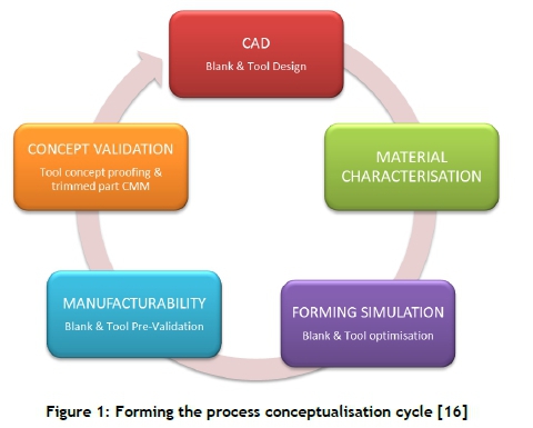
2.1 Forming the process conceptualisation cycle
Based on the simulation steps and the inputs adapted from Altan and Tekkaya [15], the forming process conceptualisation cycle depicted in Figure 1was defined and applied. The process cycle was a way to conceptualise and assess a blank and tool design effectively, taking a concept from a CAD model to the final realised component. At the heart of the process was finite element simulation, which helped to optimise and verify the blank and tooling concepts without a 'trial-and-error' process.
2.1.1 Computer-aided design (CAD)
The CAD phase's purpose was to create and prepare a surface from which the sheet blank and tooling 3D models were designed and used to conduct a forming simulation study. The models, if accepted, would be used to manufacture the actual blanks and tools. A surface was extracted from the 3D model of the component, termed the 'outer mould line' (OML) - that is, the nominal surface upon which a comparison was conducted to assess the manufactured component's conformance.
The OML nominal surface was translated and rotated until it was in the final desired orientation, and then the blank and tools were conceptualised. The initial blank was a projection of the final surface on to a pre-defined plane. The projection surface resulted in a flat blank, and was termed the 'unfolded surface;. The edges of the unfolded surface were extended (in-plane of the surface) at least 25mm, allowing for trimming to the desired component.
The tool was conceptualised based on the forming process. Similar to the blank, the OML surface was extended by 25mm. The edge extension was tangential to the surface, and followed the surface contour. The extended tool surface was then used to create an extruded solid body that depended on the depth of the fluid cell press. The extruded body's sides were then drafted 15° and the corners filleted with a 10mm radius. Once the models were created, they were saved into the initial graphics exchange specification (.igs or IGS) file format so that they could be imported into the CAE software package [5].
2.1.2 Material characterisation
The material characterisation phase covered the material properties and the other parameters required to conduct the simulation. The two most widely used unit sizes are megapascals (MPa) or gigapascals (GPa). The material properties were captured in a material card comprising the following [5]:
1. Material properties (modulus of elasticity, Poisson's ratio, and density)
2. Plasticity flow/yield criteria
3. Hardening law
4. Forming limit diagram (FLD)
5. Friction coefficients based on pressure and velocity (optional)
Friction is not a material property but rather a property of two components interfacing with one another. The friction coefficient will vary from material to material, and is further influenced by the lubricant used. The use of variable friction coefficients, dependent on the pressure and velocity, can be accommodated in PAM-STAMP, but they must be determined by experimental testing [5].
2.1.3 Forming simulation
With the geometry prepared and the material properties known, the forming simulation phase followed next. This phase was a feasibility study of the conceptualised design, to assess the degree to which the tool and blank were suitable for manufacturing the component. The mesh element size was typically coarse, with five elements across the smallest tool radius [17]. A level three mesh refinement was used to refine the mesh where required. The mesh refinement was activated in areas where the blank interfaced the tool [5].
Rubber elements were omitted in this study, similar to the studies conducted by Leacock et al. [12] and Carlsson and Vrijhof [6], in which the rubber throw pads and diaphragms were not modelled. The software developer endorsed this decision: the ESI Group recommended simulating the process without modelling the rubber throw pads and diaphragm. Rubber elements are modelled as solid elements. Thus the omission resulted in short simulation-solver times and there was no need to characterise the rubber. In addition, the complex nature of rubber-to-metal sliding [18] cannot be accurately modelled in PAM-STAMP simulations, as friction is modelled on the basis of Coulomb's friction law [5]. The omission of rubber elements meant that the effect of the rubber friction physics was not taken into account.
The surface geometries were discretised into quadrilateral and triangular shell 2D Belytschko-Tsay elements. The quadrilateral elements were the main element types, with the triangular elements being used where necessary. One-dimensional bar elements defined the trim curves [5]. The next stages of the manufacturing process were carried out in the following order:
OP 1 - Forming stage
OP 2 - Springback stage
OP 3 - Trim and springback stage
In the case of multi-stage tool operations, OP 1 and 2 were repeated before proceeding to OP 3.
To validate that the blank and tool concept was acceptable for a detailed manufacturability simulation, the following checks were performed. The FLD zone quality overlay was reviewed to assess the component for defects (wrinkling and cracking) and to ensure that enough in-pane stretching was achieved. The FLD zone check was also checked at the end of the complete process to confirm that no wrinkles or cracks occurred. The distortion of the component was validated against the desired component surface, and was then imported into PAM-STAMP. The surface derived by simulation was compared with the component's nominal shape by means of a surface distortion plot. The maximum distortion and the shape were determined, based on a distortion plot [5].
2.1.4 Manufacturability
The manufacturability phase investigated the concept in greater detail. This phase was identical to the forming simulation phase, except that the mesh element size was finer than the mesh size used in the feasibility simulation phase, but still maintaining the five elements across the smallest radius rule. A kinematic material property card was used, as it provided a more accurate form and springback than the isotropic material card. Typically, element refinement was not used in this phase because the refined mesh structure had already been imposed. The use of a finer mesh resulted in longer simulation times. As simulations are prone to errors and mistakes made by the engineer, many of the problems that could arise were corrected in the feasibility phase before proceeding to the manufacturability phase.
2.1.5 Concept validation
Once a concept was accepted from the manufacturability phase, the tooling and blank concept was manufactured. Press and trimming trials were conducted to manufacture the first article components. These components were inspected using CMM or OMM equipment and software to compare the design's final form. If the component's surface profile was within the design tolerance requirements, the blank and tooling were accepted for serial production.
3 CASE STUDY
The component used for the metallic case study was an aircraft skin panel that was manufactured by stamp forming from AA2024-W temper condition. Figure 2depicts the 2D drawing of the aircraft skin panel used in the present study. A key geometric feature of the aircraft skin panel was the s-shaped edge feature. The component was a geometrically complex surface panel that gradually transitioned from a flat plate to a complex curved surface. The complex surface made this component a good candidate for the case study.
The 2D drawing shown in Figure 2contains the critical dimensional requirements of the component. The balloons A, B, and C define the datum structure of the component. A surface profile tolerance of 1.4mm and edge profiles of 0.8mm were defined with respect to the A, B, and C datums. This datum structure was used to align the component in a standardised way for proper inspection. The component did not meet the 1.4mm surface profile dimensional requirement using male matched metal stamp forming tooling, and was manually adjusted to the final form. The case study investigated an alternative manufacturing process using a Quintus fluid cell press. The study's focus was the appropriate tool and blank development through manufacturability assessment using the PAM-STAMP 2G forming simulation package. The case study's objective was to demonstrate the capability of PAM-STAMP to conduct a die sheet hydroforming simulation.
3.1 Computer-aided design
The CAD phase's objective was to create and prepare the component OML surface so that it was suitable to import into the simulation software package. The OML surface was created with each blank and tool design created from this initial surface. An offset plane was defined from the component, based on the coordinate system at the component' s centroid.
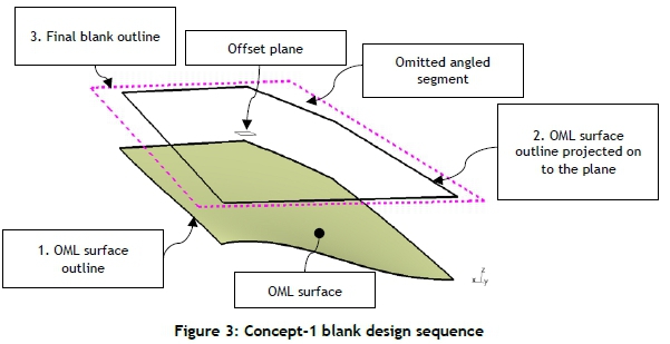
Through two rotational transformations, each corner was made equidistant from the offset plane. The final OML surface was used to create all the concepts with adaptations, based on the results' previous blank and tool concepts. The CAD phase was revisited for each blank and tooling conceptualisation. All blank and tooling concepts were created similarly. Initial blank concepts were based on the OML surface. Later, the blanks were based on tool geometry. Figure 3shows the process followed to create the blank for concept-1. An outline of the OML surface, defined previously, was created and projected on to an offset plane. The projected OML surface outline was then offset outwards, resulting in the final blank outline. The angular segment of the component was omitted to make a rectangular blank.
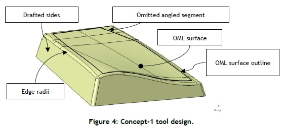
Figure 4shows concept-1's tool design. The edges of the OML surface were extended outwards tangential to the curvature of the OML surface. The angular segments of the component were omitted in the tool as well. The tool surface was extruded downwards to create a solid body with a minimum thickness of 50mm. The edges received a 20mm radius to prevent sharp corners that could result in unwanted cracks in the blank, and that could also damage the fluid cell press. The sides of the tool were drafted with a 15° angle relative to the vertical surface.
3.2 Material characterisation
Limited aluminium alloy materials were available in the ESI Group PAM-STAMP material properties database [5]. AA2024 clad sheet in 2mm thickness in the -W or -O temper conditions were not available in the PAM-STAMP database. The several PAM-STAMP material cards that were realised from the material characterisation campaign for AA2024-W 2mm thickness are listed below:
• Vegter yield locus lite plasticity law / Krupkowsky isotropic hardening law
• Vegter yield locus lite plasticity law / Yoshida-Uemori kinematic hardening law
• Vegter yield locus lite plasticity law / Yoshida-Uemori kinematic hardening law with variable Young's modulus
• A forming limit curve of the 2mm AA2024-W @30 minutes after heat solution treatment
• Variable friction curves dependent on pressure and velocity
3.3 Forming simulation: Concept-1 to concept-8
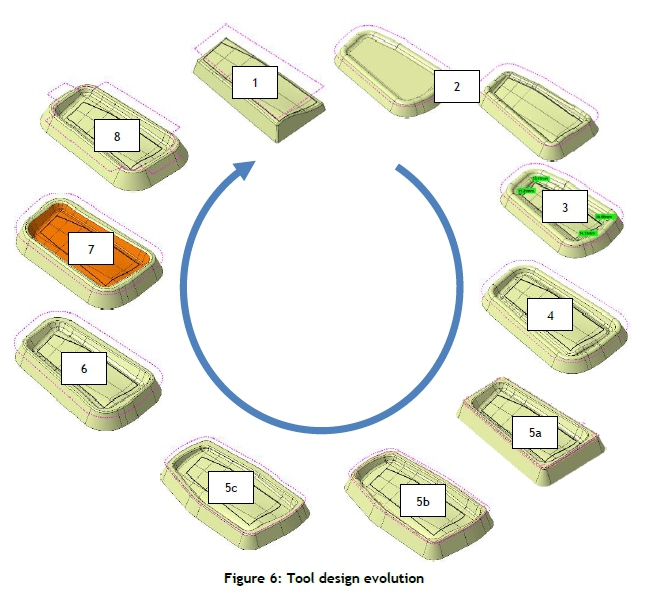
In total, 12 forming simulation feasibility studies were conducted. From concept-1 to concept-8, understanding of the fluid cell forming process and the tool and blank design requirements was established. The blank and tool design changes from concept-1 to concept-8 are shown in Figure 5and Figure 6respectively. The blank and tool design in the feasibility investigations evolved from a simple design in concept-1 to a complex flanged blank and tool in concept-8. All of the concepts, except concept-1, used the free bulging effect, thus allowing for uniform in-plane strain stretching. The objective was to make use of this feature by drawing the blank into the die cavity. This drove the tooling design from concept-2 onwards. As the free bulge effect increased the degree of the in-plane stretching that was experienced, the expectation was that less springback would be witnessed [15]. Many of the concepts lacked adequate alignment features, which were introduced in blank concept-5a and concept-8. Concept-8 also revealed that large overhanging flanges were required to increase edge restraint and in-plane stretching because of the flanges.
3.4 Manufacturability
Based on the results from all of the concepts investigated in the forming simulation phase, concept-9 was designed to meet the following criteria:
1. Large overhang blank flanges
2. Optimal tool draw depth
3. Two-stage tooling to create a pre-form blank to increase restraint loading
4. A blank alignment mechanism on the tool
The tool and blank designs from concept-7 and the findings from concept-8 were explicitly used to develop concept-9. The blank corners were rounded tangential to the flange edge. The first stage tooling had blank alignment features that allowed for quick and accurate alignment of the blank on the tool. By restraining the edges, a blankholder feature was introduced. The first stage pre-formed the blank flanges, allowing natural alignment and holding the blank during the second stage forming process. Hydropiercing was introduced for the final trim location punch hole features to be created. The formed part's location points are for accurate alignment in a computer numerically controlled (CNC) milling machine.
The simulation set-up was:
OP 1 - first forming stage: a fluid cell forming operation of the first stage tool and the flat blank. OP 2 - pre-form springback stage: springback of the pre-form.
OP 3 - second forming stage: a fluid cell forming operation of the second stage tool and the pre-formed blank
OP 4 - final form springback stage: springback of the formed component OP 5 - trimming stage: trimming of the form to the final shape
The two forming stages' total progression time was limited to 30 seconds, with a maximum pressure of 80 MPa. Once the blank came into full contact with the tool, the forming stage completed. A state result was provided every 2.5 seconds. This simulation's material card was the Vegter yield locus lite plasticity law and the Yoshida-Uemori kinematic hardening law. A friction coefficient of 0.15 was applied. The rollers were postulated to apply a restraint loading condition to the pre-formed blank during the forming process. Simulations were conducted with and without rollers. Because of the risk of pressing in the -W temper condition, the -O temper condition was also investigated.
Figure 8depicts the final form compared with the desired shape of AA2024-O temper condition without the rollers. The simulation showed that the final component had a predicted distortion of 8.392mm. The s-shaped curve was well-defined, with a predicted deviation of 0.331mm. A flattened zone occurred, and was predicted in the area of the highest springback.
3.5 Concept validation
3.5.1 Component manufacture and metrology
With a tool and blank design solution accepted, the tools and blank were manufactured to conduct press trials. AA2024-O temper condition blanks were manufactured and used for the trial. Before pressing the first stage, the selected lubricant (petroleum jelly) was applied to the tool and the blank. Figure 9depicts the final form of the blank after the first and second stage pressing. In total, four blanks were manufactured.
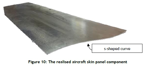
After forming, the components were trimmed using laser cutting as opposed to CNC machining, to save time. Figure 10depicts one of the realised aircraft skin panel components. The s-shaped curve was well-defined and formed, as predicted by the simulation studies.
To validate the form of the four components within the design tolerance limit of 1.4mm, a visual inspection and detailed CMM metrology investigation were conducted. The measurement of the aircraft skin panels were conducted in two configurations, unclamped and clamped, in the inspection check fixture. Figure 11 (a) shows the panel set-up in the inspection check fixture in the unclamped condition. The panel was CMM-inspected at 40 location points, with seven used for alignment using an Alpha image gantry-style CMM. Figure 11 (b) shows CMM points 8 to 40 as they were measured.
In the clamped condition, which represents the panel's installed condition in the final assembly, all four panels met the 1.4mm surface profile tolerance. The surface profile result for each panel was 0.483mm, 0.505mm, 0.478mm, and 0.817mm respectively. The unclamped surface profile result for each panel was 1.927mm, 2.153mm, 2.329mm, and 2.16mm respectively. Thus, as the clamped condition components were within the 1.4mm surface profile tolerance, the blank and tooling concepts were acceptable for serial production without the need for further modification, and so the trial and error process was omitted.
3.5.2 Metrology and simulation results comparison
The correlation between the CMM and the simulation results was explored. The process followed in the simulation to evaluate the component's anticipated final shape did not match the CMM procedure used to measure the manufactured panel's distortion. The original position alignment of the simulation mesh and the nominal surface was used throughout the investigation, and was the typical procedure seen in all the publications [2] [3] [8] - [14]. PAM-STAMP did allow for a best-fit alignment of the mesh and the component surface. However, if the tool was distortion-compensated, or there was a deviation between the CAD and CAE models, the mesh and nominal surface's initial alignment was required before using best-fit alignment. To achieve a similar alignment to what was conducted in reality, an additional gravity step was proposed. The gravity step allowed the panel to settle on to the nominal surface in a similar way to how the component settled on the inspection check fixture. This operation was considered similar to an assembly stage. Concept-9's simulation manufacturing stages were thus adapted with an addition operation: OP 6 - Gravity stage
Figure 12shows how the gravity stage improved the alignment and the overall correlation of the results compared with the best-fit alignment. No correlation between the simulation and the manufactured component was attained.
4 SIMULATION MODEL VALIDATION
Despite the final components having met the design tolerance requirement, the simulation result did not correlate with the CMM result. The only material or forming process parameter that could be altered was the friction coefficient. Hatipoglu et al. [9] made use of a friction coefficient as high as 0.9, whereas the friction coefficient used to simulate concepts 1 to 9 was a maximum of 0.19. Thus further forming simulations were carried out to determine the influence of friction.
4.1 Variable friction study
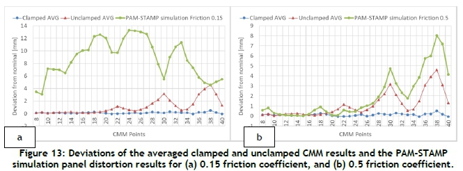
The simulation set-up of concept-9 in AA2024-O temper condition material, with the additional gravity step, was used to conduct a study to determine the influence of friction on the simulation results. The simulated friction coefficients were 0.15, 0.225, 0.45, 0.475, 0.485, 0.495, 0.5, 0.51, 0.525, and 0.55. It was found that, as the friction coefficient increased, the panel distortion decreased until it reached a friction coefficient of 0.5. No further improvement was witnessed with further increases in the friction coefficient. Figure 13provides a comparison between the 0.15 friction coefficient simulation and the 0.5 friction coefficient simulation. Both made use of the gravity stage, which was crucial for proper alignment and assessment. The line graph method of assessment does not provide a surface profile value, but shows the improved correlation between the simulated and manufactured components.
4.2 Metrology results comparison
It was uncertain to what degree the surface profile tolerance of 1.4mm was met using a line graph of the CMM points. The geometric dimensioning and tolerancing (GD&T) surface profile is defined in ISO 1101:2017, but the way it is calculated is not defined. So a surface profile deviation of the simulation result could not be determined. The lack of simulation software packages' ability to evaluate the final result based on defined metrology measurement methodologies was witnessed up to this point. The GOM Inspect 3D Metrology software package was used to conduct three evaluations:
1. Comparison of the simulation results with the nominal surface
2. Comparison of the manufactured components with the nominal surface
3. Comparison of the simulation results with the manufactured component
To conduct the proposed comparisons, the manufactured components were 3D-scanned into a stereo-lithographic (STL) facetted mesh. Surfaces were then created from the facetted mesh. A major benefit of the GOM 3D metrology software package was the alignment of the two surfaces, irrespective of the degree of misalignment.
4.2.1 Simulation to nominal surface comparison
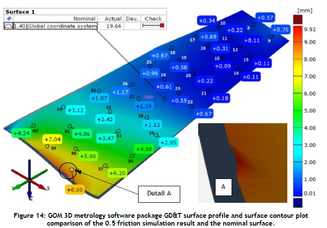
The simulation to nominal surface comparison was conducted throughout the study in PAM-STAMP. However, a surface profile value could not be attained. GOM provisioned for GD&T assessment based on the ISO 1101:2017. The gravity stage simulation with a friction coefficient of 0.15 attained a surface profile result of 22.22mm, while the gravity stage simulation with a friction coefficient of 0.5 attained a surface profile result of 19.66mm. Both deviated significantly from the desire surface profile value of 1.4mm. The surface profile for the 0.5 friction coefficient simulation is depicted in Figure 14 Detail A in Figure 14shows a manufacturing flaw that might have resulted from the panel trim line being too close to the trim location punch holes. This detail was not noticed during the review of the results in PAM-STAMP. Removing the small flaw highlighted in detail A in Figure 14improved the surface profile, resulting in a value of 6.01mm.
4.2.2 Manufactured to nominal surface comparison
To compare the actual component and nominal surface, an .stl of the actual component and an .igs model of the nominal surface were required. Figure 15depicts the two surfaces as imported into GOM before and after alignment. Irrespective of the degree of misalignment, effective alignment could be achieved, which was not easily achieved in PAM-STAMP. It was found that the surface profile of the actual component compared with the nominal surface achieved a surface profile of 19.23mm.
4.2.3 Simulation to manufactured component comparison
The final comparisons of the 0.15 and 0.5 friction coefficient simulation models were compared against the manufactured component. The 0.15 friction coefficient model achieved a surface profile of 15.74mm. However, the 0.5 friction coefficient model achieved a surface profile measurement of 7.18mm, as depicted in Figure 16
5 CONCLUSIONS
This study aimed to investigate the process of conceptualising the blank and tooling required to manufacture a complex-shaped aluminium aircraft skin panel using die sheet hydroforming. Several investigations were conducted using the ESI Group PAM-STAMP 2 simulation software package.
The forming process conceptualisation cycle showed a useful workflow, defining the steps to be taken from the design concept model to the realised component. The cycle's various steps were followed explicitly, and proved vital when deciding to proceed to the next step in the conceptualisation cycle. Even without explicitly modelling the rubber elements, a successful die sheet hydroformed simulation result could be conducted, and a final component was obtained. However, the rubber-to-metal friction coefficient must be incorporated appropriately, at a higher value than the conventional metal-to-metal friction coefficient of 0.15.
To assess the final simulation result, the post-assessment procedures in a simulation software package require development. PAM-STAMP cannot assess a component according to standard metrology methods. A third-party software package, GOM Inspect 3D metrology, was used to assess the component and determine whether it was within the desired specification. This process is simulation metrology, and is a new area of interest that should be incorporated into simulation software packages to offer the customer a standardised method to confirm the simulation's output.
In addition to the forming, springback, and trimming stages of the digital manufacturing simulation process, an operation was introduced to align the two components to correlate the simulation and the CMM results. The gravity stage led to an assembly installation stage that provided a more accurate correlation with the manufactured component. The blank and tool concept's predicted capability to manufacture a suitable component for installation into the final assembly was realised with the gravity operation.
The research showed better design process efficiency with the omission of the trial-and-error correction method. Without the need physically to trial several blank and tool concepts, a significant saving was achieved through a resource-efficient development process. This research contributes to improving the sheet metal forming simulation process and the simulation of the die sheet hydroforming process. This study will benefit the aerospace and automotive industry and promote the adoption of digital manufacturing processes.
REFERENCES
[1] Altan, T. & Tekkaya, A. (eds). 2012. Sheet metal forming fundamentals Volume 1. Materials Park, OH: ASM International. [ Links ]
[2] Yershov, A., Kotov, V. & Loginov, Y. 2012. Optimisation of the initial form of a semifinished product in PAM-STAMP 2g. Metallurgist, 56(3-4), pp. 231-235. [ Links ]
[3] Dirikolu, M.H. & Akdemir, E. 2004. Computer aided modelling of flexible forming process. Journal of Materials Processing Technology, 148, pp. 376-381. [ Links ]
[4] Hatipoglu, H.A. & Alka§, C.O. 2016. Process modelling and die design concepts for forming aircraft sheet parts. Journal of Physics: Conference Series, 734, 032088. [ Links ]
[5] ESI Group. 2018. PAM-STAMP sheet metal forming software user's guide. https://myesi.esi-group.com/downloads/software-downloads/pam-stamp-2018.0, October 2020. [ Links ]
[6] Carlsson, B. & Vrijhof, S. 2018. White paper on the successful simulation of flexforming processes at Quintus Technologies. [Online]. Available: https://formingworld.com/quintus-technologies-flexforming/ Accessed on: 12 July, 2020. [ Links ]
[7] Bell, C., Corney, J., Zuelli, N. & Savings, D. 2020. A state of the art review of hydroforming technology. International Journal of Material Forming, 13, pp. 789-828. [ Links ]
[8] Lee, M., Korkolis, Y.P. & Kim, J.H. 2015. Recent developments in hydroforming technology. Proceedings of the Institution of Mechanical Engineers, Part B: Journal of Engineering Manufacture, 229(4), pp. 572-596. [ Links ]
[9] Hatipoglu, H.A., Polat, N., Köksal, A. & Tekkaya, E. 2007. Modeling flexforming (fluid cell forming) process with finite element method. Key Engineering Materials, 344, pp. 469-476. [ Links ]
[10] Chen, L., Chen, H., Wang, Q. & Li, Z. 2015. Studies on wrinkling and control method in rubber forming using aluminium sheet shrink flanging process. Materials and Design, 65, pp. 505-510. [ Links ]
[11] Pãunoiu, V., Teodor, V.G. & Susac, F. 2015. Researches regarding the hydroforming process of aluminum components. IOP Conf. Series: Materials Science and Engineering, 95, 012016. [ Links ]
[12] Leacock, A., Ling, D. & Bergkvist, M. 2016. Industrial application and validation of forming simulation in the flexforming process. Journal of Physics: Conference Series, 734, 032103. [ Links ]
[13] Pãunoiu, V., Pereira, F., Teodor, V.G. & Maier, C. 2019. Investigation of hydroforming technology for manufacturing an auto complex part. Materials Science Forum, 957, pp. 138-147. [ Links ]
[14] Zhang, L., Zhou, S., Zhao, T. & Zeng, Y. 2019. An intelligent method to design die profile for rubber forming of complex curved flange part. International Journal of Precision Engineering and Manufacturing, 20, pp. 111-119. [ Links ]
[15] Altan, T. & Tekkaya, A. (eds). 2012. Sheet metal forming processes and applications Volume 1. Materials Park, OH: ASM International. [ Links ]
[16] Serfontein, J.L., Dimitrov, D. & Gerber, W. 2019. Composite and metallic forming manufacturability criteria for incorporation into material selection methodology. Dimitrov, D., Hagedorn-Hansen, D. & Von Leipzig, K. 2019. Conference Proceedings - International Conference on Competitive Manufacturing, COMA19, presented at Stellenbosch Univerisy, January 30 - February 1 2019, Stellenbosch University, Stellenbosch, South Africa, pp. 337-345. [ Links ]
[17] Chen, L., Chen, H., Guo, W., Chen, G. & Wang, Q. 2014. Experimental and simulation studies of springback in rubber forming using aluminium sheet straight flanging process. Materials and Design, 54, pp. 354-360. [ Links ]
[18] Gómez, M.A., Gallardo-Hernández, E.A., Vite Tores, M. & Peña Bautista, A. 2013. Rubber steel friction in contaminated contacts. Wear, 302, pp. 1421 -1425. [ Links ]
Submitted by authors 2 Mar 2021
Accepted for publication 21 Sep 2021
Available online 14 Dec 2021
* Corresponding author: serfontj@gmail.com

