


Services on Demand
Article
 English (pdf)
 Article in xml format
 Article references
Indicators

Related links
-
 Cited by Google
 -
 Similars in Google
Share

 Permalink
South African Journal of Industrial Engineering
On-line version ISSN 2224-7890
Print version ISSN 1012-277X
S. Afr. J. Ind. Eng. vol.32 n.1 Pretoria May. 2021
http://dx.doi.org/10.7166/32-1-2382
GENERAL ARTICLES
Synthesis of a novel five-degrees-of-freedom parallel kinematic manipulator
W.E. Dharmalingum*, #; J. Padayachee; G. Bright
Discipline of Mechanical Engineering, School of Engineering, University of KwaZulu-Natal, South Africa. W.E. Dharmalingum: https://orcid.org/0000-0002-4015-1087; J. Padayachee: https://orcid.org/0000-0003-0358-5289; G. Bright: https://orcid.org/0000-0003-4386-0329
ABSTRACT
This paper presents the design and analysis of a novel five degrees-of-freedom (DOF) parallel kinematic manipulator (PKM) for part-handling, sorting, general positioning, and robotic machining applications. The 2-R(Pa-IQ)RR, R(Pa-IQ)R manipulator has two rotational DOFs, one parasitic rotation, and three translational DOFs. In comparison with other 5- and 6-DOF PKMs, this PKM possesses three pairs of coplanar legs that contain nested kinematic chains, and it makes exclusive use of revolute and prismatic joints. The inverse kinematic analysis is a novel extension of the geometric (vector) method with the analysis of inner and outer kinematic chains. The forward kinematic analysis was solved using the Newton Raphson (NR) method. The results of the forward and inverse kinematic analyses were validated with SolidWorks® and MATLAB® simulations.
OPSOMMING
Die ontwerp en analise van 'n nuwe vyf grade van vryheid parallele kinematiese manipuleerder (PKM) vir onderdeel hantering, sortering, algemene posisionering en robot masjinering toepassings word aangebied. Die manipuleerder het twee rotasie vryheidsgrade, een parasitiese rotasie en drie translasie vryheidsgrade. In teenstelling met ander vyf- en ses vryheidsgraad PKM's, besit hierdie PKM drie pare saamvlakkige bene wat geneste kinematiese kettings bevat en dit maak uitsluitlik gebruik van omwentelings- en prismatiese gewrigte. Die inverse kinematiese analise is n nuwe uitbreiding van die geometriese (vektor) metode saam met die analise van binne- en buite kinematiese kettings. Die vorentoe kinematiese analise is opgelos deur die Newton-Raphson metode. Die resultate van beide die vorentoe- en inverse kinematiese analises is gevalideer met SolidWorks® en MATLAB® simulasies.
1 INTRODUCTION
In recent decades, there has been much interest, and there have been significant advancements, in the field of parallel kinematic manipulators (PKMs). They have been adopted in industry for tasks such as positioning, pick-and-place operations, motion simulation, machining tasks, and medical operations [1]. A PKM is defined as a robotic system that has two or more closed-loop kinematic chains. Each kinematic chain is connected to a common base and to a common end effector [1]. PKMs exhibit higher mechanical stiffness and lower inertia than serial architectures [1]. They are capable of a high payload-to-weight ratio; however, PKMs generally have smaller workspaces than serial robots. PKMs are known to require complex calibration methods and kinematic analyses. The forward kinematic analysis, in particular, generally leads to nonlinear equations that require the use of numerical methods to solve [2].
Serial and parallel kinematic architecture robots have been explored as alternative machining centres to computer numerically controlled (CNC) machines. Researchers such as Karim and Verl [3] and Brüning et al. [4] confirmed that there is a high economic potential for using robotic systems to perform machining tasks in the aerospace and automotive industries. The disadvantages of serial robotic systems include the error accumulation in joints that is propagated through all links; also, they possess relatively low mechanical stiffness, are prone to vibrating, and require complex programming [3, 4]. Research conducted on serial robotic platforms showed that, under heavy machining, stiffness is compromised and joint error propagation is observed [5, 6]. A PKM designed for machining tasks can be employed for high-accuracy positioning, part-handling, and sorting applications. Owing to its high stiffness and the averaging of joint errors, a PKM would be better suited for - but not limited to - machining applications.
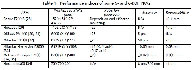
Researchers have proposed various PKMs and hybrid architectures that can be employed for machining, positioning, part-handling, and sorting tasks in industry. A number of these robotic platforms have been successfully commercialised; however, they are large and expensive [1, 7, 8]. This research was motivated by the need for a compact, affordable, and multi-purpose robotic architecture with larger ranges of rotation than most 5- and 6-DOF PKMs. The PKM was designed to validate machining, part-handling, sorting, and general positioning applications.
The paper presents the design and synthesis of a novel 5-DOF PKM. The kinematic analyses are presented and the merits of the novel architecture are evaluated. This paper is arranged as follows: Section 2 analyses parallel kinematic platforms that can be used for machining, part-handling, sorting, and general position applications; and industrially available platforms are reviewed. Section 3 presents the description of the novel design; Section 4 presents the inverse kinematic analysis; Section 5 presents the forward kinematic analysis; Section 6 presents the results from simulations used to validate the forward and inverse kinematic models; and Section 7 concludes with insights from this study and recommends areas for future research and development.
2 APPLICATIONS OF PARALLEL ROBOTS
PKMs can accomplish a wide variety of tasks. Within this class of robots, architectural sub-classes exist that influence the functionality of the PKM [9]. Applications of interest were reviewed. Concerning part-handling and sorting, Yang et al. [l0] produced a modified robust control system for the 2-DOF diamond parallel robot. This robotic platform was designed for high-speed and high-precision part handling and assembly. Experimental results showed that the modified control system was successful and could produce more accurate trajectories than traditional potential difference methods. Ahangar et al. [11] produced a novel 3-DOF Delta-type PKM with redundant actuation, which could be used in a production line with the addition of a magnetic joint. In a study carried out by Al-Naimi, Taeim and Alajdah [12], a 3-DOF PKM was designed to detect, locate, grasp, and transfer a part to a different position while using machine vision. The robotic platform conducted tasks within acceptable accuracies. A 6-DOF PKM was developed by McCann and Dollar [13] for dexterous spatial manipulation. The design was based on the Stewart platform, and the results showed that the PKM could manipulate shapes in space with minimal sensing. The machine did, however, encounter challenges when grasping irregular objects. Other notable PKMs known for their good performance in part-handling and sorting applications are the ABB IRB 360 Flex Picker [14], Delta Robots developed by SIG Pack Systems [1], and the Fanuc M-31A manipulator [12]. PKMs that possess up to four DOFs for part handling and sorting are generally high-speed robotic platforms with low inertia. The motors are located at the base. PKMs that possess five or six DOFs for such applications have higher inertia, but possess greater stiffness, allowing for fine positioning and more dexterous manipulation.
For general positioning, a novel 5-DOF PKM developed by Guo et al. [15] was used as a ship active vibration isolation system using PID control and force-position redundant control. ADAMS®-MATLAB Simulink® simulations were used to improve further the control of the PKM. The results showed that acceptable tracking was achieved and that vibration isolation was successful. Research conducted by Fiore, Giberti and Sbaglia [16] entailed the kinematic optimisation of a 5-DOF PKM for additive manufacturing. The workspace was designed for the desired task through a genetic algorithm. The PKM could achieve movements that were not feasible with traditional additive manufacturing machines. Gonzalez and Asada [17] developed a 6-DOF triple scissor extender (TSE) PKM for aircraft assembly applications. The purpose of this design was to achieve a large workspace by reaching high ceilings and fine positioning of the end effector. The testing showed that the TSE PKM could reach 1.2 meters in the X and Y directions and that fine positioning was realised. A 6-DOF PKM researched by Stenzel, Sajkowski and Hetmanczyk [18] was applied to simulations of selected manoeuvres for emergency vehicles. The platform simulated the forces acting on the load of a vehicle for driving over a speed bump and for obstacle avoidance. The 6-DOF Fanuc F-200iB was investigated by Barnfather, Goodfellow and Abram [19] to determine and minimise position errors in the robotic platform during non-cutting stages. Position errors were observed in the micron range and were pose-dependent. It was proposed that the systematic error be reduced through in-situ process monitoring. PKMs possessing five and six DOFs are better suited for positioning tasks than PKMs possessing four DOFs or fewer. The workspace can be tailored to suit the desired task. There is a trade-off between large workspace and machine stiffness. Larger workspaces require all motors to be mounted at the foot points of the PKM.
Briot, Pashkevich and Chablat [20] identified that the load-bearing advantage and higher positional accuracy of parallel robots, compared with serial robots, make them a more suitable robotic platform for machining applications [21]. A 6-DOF free leg hexapod was developed by Olarra, Allen and Axinte [22] for miniature machining applications. An algorithm was developed to alter the machine's architectural configuration. This generated the required workspace to suit the desired application through an optimal foot configuration. A study undertaken by Glavonjic et al. [23] produced a desktop 3-DOF spatial PKM for machining applications. The study was aimed at producing a low-cost educational robotic platform. The results showed that the platform could only machine soft materials. The Orthoglide, developed by Chablat and Wenger [24], possessed three translational degrees of freedom, and was also considered for machining applications. The PKM used parallelogram joints. These platforms have been developed and tested, but have not been adopted industrially. Some of these platforms have future work pending, inclusive of testing and experimentation.
Choi, Cho and Kim [25] developed a PKM that was mobile and could move to a desired location to perform machining tasks. The first prototype that was built was inferior to a CNC machine for feed rate and accuracy of cut. Further research was required to develop path-planning algorithms, and additional sensors were required to aid in the control of the machine. In a research study carried out by Jin et al. [26], their team developed a PKM, named PAW, for drilling and trimming tasks for aircraft wings. It was designed to be mounted on a gantry structure that allowed it to move to different locations. The machine possessed one translational and two rotational DOFs. Dimensional analysis confirmed that the PAW PKM performed machining tasks better than mechanisms currently employed in industry. Compared with a Tricept-type PKM, it performed better for accuracy and stiffness owing to the removal of the wrist segment employed by Tricept-type PKMs. The Exechon, which is industrially available, improved on the Tricept-type PKM architecture. The Exechon, like Tricept-based PKMs, is a hybrid PKM with a 3-DOF PKM portion and a 2-DOF serial wrist mounted on the end effector [27]. The OKUmA PM 600 possesses six DOFs, and has been commercialised. The design was based on the Stewart platform. It is used for machining aluminium and work pieces that require less polishing [7]. PKMs employed in industry are generally large and expensive.
Research indicates that, although novel PKMs are analytically functional and have excellent performance potential, their adoption in industry is hindered by some PKMs being developed as an educational exercise, with future work pending [11, 36, 37]. Further research is needed to adopt a PKM that is compact and affordable, for a range of tasks in industry.
3 PKM DESCRIPTION
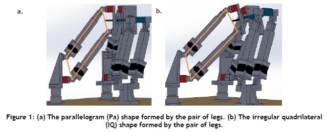
The novel architecture, named the 2-R(Pa-IQ)RR, R(Pa-IQ)R parallel manipulator, is shown in Figures 1 and 2. Notable characteristics of the PKM are listed below:

• The architecture is capable of x, y, and z translation and rotations about the x- and y-axes.
• The leg arrangement restricts the independent rotation about the z-axis, but permits it as a parasitic motion.
• All prismatic joints are actuated, and all revolute joints are passive.
• Legs are paired to create a nested kinematic loop inside an outer, closed kinematic loop.
• Each pair of legs is constrained to move along the same plane relative to each other.
• When the PKM performs translational motion, the nested kinematic loop takes on the shape of a parallelogram (Pa) structure, shown in Figure 1(a).
• When the end effector is rotated, the nested kinematic loop takes on the shape of an irregular quadrilateral (IQ) structure, shown in Figure 1(b).
4 INVERSE KINEMATIC ANALYSIS
4.1 Methodology
The inverse kinematic analysis solves the joint angles and/or the actuator lengths for a given position and orientation of the end effector for a kinematic chain. The geometric (vector) method was selected, since it is simpler than the Denavit-Hartenberg (DH) method for PKMs [2]. The roll, pitch, and yaw rotation sequence were used in accordance with the Tait-Bryant angles. This suggests that the rotation first occurs about the x-axis (roll), then about the y-axis (pitch), and finally about the z-axis (yaw).
The parasitic motion was not investigated in this study; therefore the rotation matrix is simplified as presented in Equation 1 for γ = 0.

where c and s represent cosine and sine respectively. The outer and inner vector loop equations were developed and computed through MATLAB®. The results from the MATLAB® computations were verified with data from the SolidWorks® three-dimensional (3D) modelling package.
4.2 Inverse kinematic relationships through the outer loop method
The position and the orientation of the end effector are inputs for the inverse kinematic analysis, which solves the length of each leg of the platform. Generally, the vector loop method is simple and trivial to solve when the bottom of the actuator is directly connected to the base of the machine, and the top of the actuator is connected to the end effector. The vector method used in this research is a novel approach, and is a variation of the vector loop analysis commonly found in the literature. A novel approach was required owing to joint offsets and nested kinematic loops. These offsets make the inverse kinematic analysis complex owing to the relative motion between the links, and introduces additional variables [38, 39].

The vector 7)2 is the position of Point A with respect to Point 0 in terms of x, y, and z displacements. Similarly, the vector P~D is the position of Point D with respect to Point P. Vector OA and P~D are machine design parameters. The vector OP is the position of Point Ρrelative to Point 0. Point Ρis always known relative to Point 0, because this is a requirement to solve the inverse kinematic equations. Vector ÄD (Point D relative to Point A) can then be solved as the only unknown. Two different paths were taken to reach point D on the end effector from point 0 (the reference point for the global coordinate system).
The homogeneous transformation matrix is applied to vector P~D for two reasons. The first is because Point Ρis a dynamic point in space. Therefore the position of the moving reference frame (local coordinate system at Point P) needs to referenced to the fixed frame (global coordinate system at Point 0) because Point D is referenced within the local coordinate frame. The second reason for transforming vector PD is associated with the rotation of the end effector. The plane along which the local coordinate system is located is rotated when the end effector rotates. This rotation does not affect the magnitude of the vector; however, it affects the x, y, and z values of the vector in space, which needs to be augmented, since all computations are carried out in terms of vector components.
The outer vector loop equation is shown in Equation 2, which can be applied to all pairs of legs. The true length of an actuator is from point Βto point C, and is solved by the inner vector loop analysis.

The outer vector loop equation for leg pair 1 and 2 is given by Equation 3, and is expanded:

Now let each equation be isolated as follows:

The magnitude of vector A1,2D1,2 is found by the following:

The magnitude of vector A1,2D1,2was used in the next step for the inner vector loop calculations.
4.3 Inverse kinematic relationships through the inner loop method
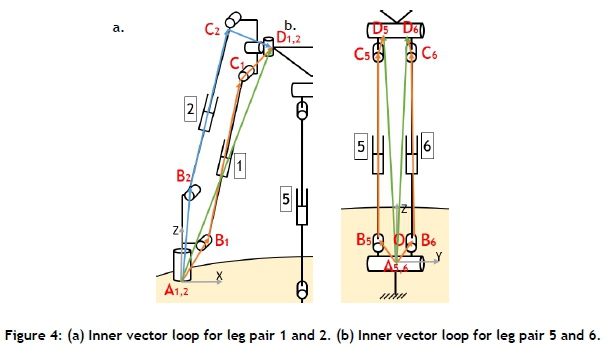
The inner vector loop diagrams for leg pair 1 and 2 can be seen in Figure 4(a). Vector loops are constructed by taking two paths from point A to point D, shown in blue and orange respectively. The vector AD is solved from the outer loop equation. The mechanical arrangement of legs and joints in the PKM constrains each pair of legs to move along the same plane. This allows the inner loop vector analysis to be treated as a two-dimensional (2D) analysis. Vector AD can be used to solve the length of the actuators, B1C1and B2C2for legs 1 and 2 respectively. Vector AB and vector CD are machine design parameters, and the solution is given by Equation 10. The same methodology is applied to solve the lengths of all the other leg pairs. Leg pair 5 and 6 is shown in Figure 4(b), with the inner vector loop shown in orange. The solution to leg lengths 5 and 6 is given by Equations 12 and 13 respectively.
The inner vector loop equations are given by Equations 10 to 13:

The inner loop vector calculations were carried out along a 2D plane. The vector AD had to be reduced from a 3D vector to a 2D vector for the analysis. As in Figure 4(a), a coordinate system was placed at point A, which established an x-z plane. The y component of vector AD could be omitted without losing vector integrity. The z value for vector AD from the outer loop was kept for the inner loop analysis. Since the z value and the magnitude of vector AD were known, the new x value for vector AD was found through the theorem of Pythagoras. This method remained the same when computing vector AD for the new x values for leg pair 3 and 4, since they were identical to leg pair 1 and 2. The analysis was similar when computing the values for vector AD for leg pair 5 and 6, except that the y magnitude was retained from the outer loop analysis and the x magnitude was omitted. A new z value was computed for leg pair 5 and 6.
The calculation procedure using the inner vector loop method is shown in Equation 14 for actuator 1 and 2.
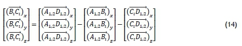
Since Equation 14 relates to the x-z plane, all of the y elements were zero.

Let:

The magnitude of vector ßiCv is found by the following:


The rotational analysis for vector C1D1,2is carried out as follows for leg length 1:

The new C1D1,2vector is given by the following trigonometric calculation:
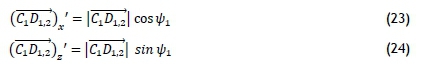
When rotation occurs, (ClD1,2)xand (C1D1,2)zare substituted by (ClD1,2)x1 and (ClD1,2)z' respectively in Equation 14.
5 FORWARD KINEMATIC ANALYSIS

The forward kinematic equations were derived from the inverse kinematic equations, and were adjusted for the NR method. Additional equations were developed for the forward kinematic analysis owing to the outer vector loop being common to a pair of legs.
Only one outer vector loop and one inner vector loop equation were developed for each leg pair, and additional equations were found through a close analysis of the unique PKM. The constraint equations for the translation case are described by Equations 25 to 27 for leg 1. Similar equations were developed for the other leg pairs, and so six equations were developed.

The alpha and beta rotational equations were formulated from the equations for the translational case, but were expanded. One additional equation was required for the alpha and beta rotation. The additional equation for the isolated alpha rotation is seen in Equation 28. A similar equation was formulated for the isolated beta rotation case.

6 EXPERIMENTS AND RESULTS
The validation of the inverse and forward kinematic analyses were accomplished through MATLAB® and SolidWorks®. The PKM was moved freely within the SolidWorks® model space, and reference points as well as local and global coordinate systems were created. This allowed each point of interest on the robotic platform to be located accurately. Virtual sensors were placed in SolidWorks® so that the leg lengths could be measured, and this became the control data against which the kinematic equations calculations were measured. MATLAB® was used to perform all forward and inverse kinematic calculations.
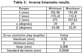
The errors seen in the inverse kinematic tests can be attributed to rounding off errors, thus validating the inverse kinematic equations. The inverse kinematic analysis exhibited high accuracy, irrespective of the position and angle of tilt of the end effector. The high accuracy was also maintained when random sample points were chosen across the PKM's workspace.

The forward kinematic results validated the equations. The results show that the method produces highly accurate solutions, and most errors can be attributed to rounding-off. The NR algorithm generally converges to the true value within five to 30 iterations, even when the guesses deviate considerably from the true value. Convergence occurred with an average of eight iterations.
7 CONCLUSION
The design made exclusive use of revolute and prismatic joints. The exclusive use of revolute joints, which cause relative motion, as opposed to universal joints, was further complicated by nested kinematic loops. When the end effector moves in pure translation, the leg pairs forming the nested kinematic loops are equal in length. Rotation occurs when the legs within the leg pair extend and/or contract to different leg lengths. The range of tilt achieved for alpha and beta is 71.46° and 63.97° respectively. Greater tilt is achieved than with most commercially available PKMs, such as the Hexabot, the OKUMA PM 600, and the Mikrolar P1500.
The inverse kinematic analysis was solved by the vector method - which was novel - through the analysis of the inner and outer kinematic chains. The forward kinematic analysis was solved using the NR method. The results from the inverse kinematic analysis showed that the largest error among the six legs was 0.02 mm. The forward kinematic simulations revealed that the largest position and angular errors were 0.05 mm and 0.05 degrees respectively. The results validated the forward and inverse kinematic equations. Future work on this PKM includes stiffness analysis, path planning, machine calibration, open architecture control, parasitic motion investigation, and Simulink models.
ACKNOWLEDGEMENTS
The authors wish to thank the University of KwaZulu-Natal and the National Research Foundation under the Thuthuka Grant (TTK170421228180).
REFERENCES
[1] Pandilov, Z. & Dukovski, V. 2014. Comparison of the characteristics between serial and parallel robots. Acta Technica Corviniensis-Bulletin of Engineering, 7(1), pp. 143-160. [ Links ]
[2] Tsai, L.-W. 1999. Robot analysis: The mechanics of serial and parallel manipulators. 1st ed. New York: John Wiley & Sons. [ Links ]
[3] Karim, A. & Verl, A. 2013. Challenges and obstacles in robot-machining. In IEEE International Symposium on Robotics (ISR) 2013, Seoul, pp. 1-4. [ Links ]
[4] Brüning, J., Denkena, B., Dittrich, M.A. & Park, H.-S. 2016. Simulation based planning of machining processes with industrial robots. Procedia Manufacturing, 6, pp. 17-24. [ Links ]
[5] Wang, J., Zhang, H. & Fuhlbrigge, T. 2009. Improving machining accuracy with robot deformation compensation. In 2009 IEEE/RSJ International Conference on Intelligent Robots and Systems, St Louis, USA, pp. 3826-3831. [ Links ]
[6] Schneider, U., Drust, M., Diaz Prosada, J. & Verl, A. 2013. Position control of an industrial robot using an optical measurement system for machining purposes. In Proceedings of the 11th International Conference on Manufacturing Research (ICMR2013), Cranfield University, UK, pp. 307-312. [ Links ]
[7] Pandilov, Z. & Rall, K. 2006. Parallel kinematics machine tools: History, present, future. Mechanical Engineering - Scientific Journal, 25(1), pp. 3-20. [ Links ]
[8] Borràs, J. & Thomas, F. 2010. Singularity-invariant leg substitutions in pentapods. In 2010 IEEE/RSJ International Conference on Intelligent Robots and Systems, Taipei, pp. 2766-2771. [ Links ]
[9] Koseki, Y., Arai, T., Sugimoto, K., Takatuji, T. & Goto, M. 1998. Design and accuracy evaluation of high-speed and high precision parallel mechanism. In 1998 IEEE International Conference on Robotics and Automation Proceedings (Cat. No.98CH36146), Leuven, Belgium, pp. 1340-1345. [ Links ]
[10] Yang, X., Zhu, L., Ni, Y., Lui, H., Zhu, W., Shi, H. & Huang, T. 2019. Modified robust dynamic control for a diamond parallel robot. IEEE/ASME Transactions on Mechatronics, 24(3), pp. 959-968. [ Links ]
[11] Ahangar, S., Mehrabani, M.V., Shorijeh, A.P. & Masouleh, M.T. 2019. Design a 3-DOF delta parallel robot by one degree redundancy along the conveyor axis, A novel automation approach. In 2019 5th Conference on Knowledge Based Engineering and Innovation (KBEI), Tehran, pp. 413-418. [ Links ]
[12] Al-Naimi, I., Taeim, A. & Alajdah, N. 2018. Fully-automated parallel-kinematic robot for multitask industrial operations. In 2018 15th International Multi-Conference on Systems, Signals & Devices (SSD), Hammamet, pp. 390395. [ Links ]
[13] McCann, C.M. & Dollar, A.M. 2017. Design of a Stewart platform-inspired dexterous hand for 6-DOF within-hand manipulation. In 2017IEEE/RSJ International Conference on Intelligent Robots and Systems (IROS), Vancouver, BC, pp. 1158-1163. [ Links ]
[14] Nordin, M.H., Selvaraju, K. & Fathullah, M. 2016. Increasing ABB flexpicker robot's degree of freedom (DOF) using flexible end effector. MATEC Web of Conferences, 78, pp. 1-9. [ Links ]
[15] Guo, J., Li, G., Li, B. & Wang, S. 2014. A ship active vibration isolation system based on a novel 5-DOF parallel mechanism. In 2014 IEEE International Conference on Information and Automation (ICIA), Hailar, pp. 800-805. [ Links ]
[16] Fiore, E., Giberti, H. & Sbaglia, L. 2015. Dimensional synthesis of a 5-DOF parallel kinematic manipulator for a 3d printer. In 2015 16th International Conference on Research and Education in Mechatronics (REM), Bochum, pp. 4148. [ Links ]
[17] Gonzalez, D.J. & Asada, H.H. 2017. Design and analysis of 6-DOF triple scissor extender robots with applications in aircraft assembly. IEEE Robotics and Automation Letters, 2(3), pp. 1420-1427. [ Links ]
[18] Stenzel, T., Sajkowski, M. & Hetmanczyk, J. 2016. Application of 6-DOF parallel manipulator for simulation of selected manoeuvres of emergency vehicles. In 2016 21st International Conference on Methods and Models in Automation and Robotics (MMAR), Miedzyzdroje, pp. 251-255. [ Links ]
[19] Barnfather, J.D., Goodfellow, M.J. & Abram, T. 2017. Positional capability of a hexapod robot for machining applications. The International Journal of Advanced Manufacturing Technology, 89(1), pp. 1103-1111. [ Links ]
[20] Briot, S., Pashkevich, A. & Chablat, D. 2010. Optimal technology-oriented design of parallel robots for high-speed machining applications. In 2010 IEEE International Conference on Robotics and Automation, Anchorage, pp. 11551161. [ Links ]
[21] Plitea, N., Lese, D., Pisla, D. & Vaida, C. 2013. Structural design and kinematics of a new parallel reconfigurable robot. Robotics and Computer-Integrated Manufacturing, 29(1), pp. 219-235. [ Links ]
[22] Olarra, A., Allen, J.M. & Axinte, D.A. 2014. Experimental evaluation of a special purpose miniature machine tool with parallel kinematics architecture: Free leg hexapod. Precision Engineering, 38(3), pp. 589-604. [ Links ]
[23] Glavonjic, M., Milutinovic, D., Zivanovic, S., Dimic, Z. & Kvrgic, V. 2010. Desktop 3-axis parallel kinematic milling machine. The International Journal of Advanced Manufacturing Technology, 46(1), pp. 51-60. [ Links ]
[24] Chablat, D. & Wenger, P. 2003. Architecture optimization of a 3-DOF translational parallel mechanism for machining applications, the orthoglide. IEEE Transactions on Robotics and Automation, 19(3), pp. 403-410. [ Links ]
[25] Choi, S., Cho, C.N. & Kim, H.-J. 2015. Development of hexapod robot for machining. In 2015 15th International Conference on Control, Automation and Systems (ICCAS), Busan, pp. 738-740. [ Links ]
[26] Jin, Y., Kong, X., Higgins, C. & Price, M. 2012. Kinematic design of a new parallel kinematic machine for aircraft wing assembly. In IEEE 10th International Conference on Industrial Informatics, Beijing, pp. 669-674. [ Links ]
[27] Bi, Z.M. & Jin, Y. 2011. Kinematic modeling of Exechon parallel kinematic machine. Robotics and Computer- Integrated Manufacturing, 27(1), pp. 186-193. [ Links ]
[28] Robolution. 2017. FANUCF-200iBrobot. [Online]. Available: http://robolution.eu/robot/f-200ib. [Accessed: June 5, 2017]. [ Links ]
[29] Merlet, J.-P. 2006. Parallel robots. 2nd ed., ed. G.M.L. Gladwell. Vol. 128. Dordrecht: Springer Science & Business Media. [ Links ]
[30] OKUMA. 2012. PM-600. [Online]. Available: https://www.scribd.com/doc/210600538/Okuma-PM-600-pdf. [Accessed: August 7, 2017]. [ Links ]
[31] Bonev, I. 2002. Gallery of existing parallel mechanisms. [Online]. Available: https://www.parallemic.org/WhosWho/Gallery.html#. [Accessed: May 14, 2020]. [ Links ]
[32] Mikrolar. 2016. P1500 Hexapod. [Online]. Available: http://mikrolar.com/plite.html. [Accessed: October 10, 2018]. [ Links ]
[33] Mikrolar. 2016. P3000 Hexapod. [Online]. Available: http://mikrolar.com/p3000.html. [Accessed: October 10, 2018]. [ Links ]
[34] Weck, M. & Staimer, D. 2002. Parallel kinematic machine tools: Current state and future potentials. CIRP Annals, 51(2), pp. 671-683. [ Links ]
[35] Metrom Mechatronische Maschinen GmbH. 2018. Optimum solution - Icosaeder structure + Pentapod kinematics. [Online]. Available: https://www.gefertec.de/wp-content/uploads/2018/06/3DMP_Forum_2018_Marcus_Witt_Metrom_GmbH.pdf. [Accessed: April 5, 2019]. [ Links ]
[36] Azmoun, M., Rouhollahi, A., Masouleh, M.T. & Kalhor, A. 2018. Kinematics and control of a 4-DOF Delta Parallel Manipulator. In 2018 6th RSI International Conference on Robotics andMechatronics (IcRoM), Tehran, pp. 494-500. [ Links ]
[37] Jeridi, R., Ghommam, J. & Benali, A. 2018. Design of a parallel mechanism as an assistance tool for thorax orientation. In 2018 15th International Multi-Conference on Systems, Signals & Devices (SSD), Hammamet, pp. 408-413. [ Links ]
[38] Yu, Y., Xu, Z.-B., Wu, Q.-W., Yu, P., He, S. & Wang, G.-Q. 2017. Kinematic analysis and testing of a 6-RRRPRR parallel manipulator. Proceedings of the Institution of Mechanical Engineers, Part C: Journal of Mechanical Engineering Science, 231(13), pp. 2515-2527. [ Links ]
[39] Dalvand, M.M., Shirinzadeh, B. & Nahavandi, S. 2013. Inverse kinematics analysis of 6-RRCRR parallel manipulators. In 2013 IEEE/ASME International Conference on Advanced Intelligent Mechatronics, Wollongong, NSW, pp. 644-648. [ Links ]
[40] Abo-Shanab, R.F. 2014. An efficient method for solving the direct kinematics of parallel manipulators following a trajectory. Journal of Automation and Control Engineering, 2(3), pp. 228-233. [ Links ]
[41] Jakobovic, D. & Budin, L. 2002. Forward kinematics of a Stewart platform mechanism. Faculty of Electrical Engineering and Computing, Unska, Zagreb, Croatia. [ Links ]
Submitted by authors 25 Jun 2020
Accepted for publication 12 Jan 2021
Available online 28 May 2021
# The author was enrolled for an MSc Eng (Mechanical) degree in the Discipline of Mechanical Engineering, University of KwaZulu-Natal, South Africa
* Corresponding author: DharmalingumW@ukzn.ac.za

