


Services on Demand
Article
 English (pdf)
 Article in xml format
 Article references
Indicators

Related links
-
 Cited by Google
 -
 Similars in Google
Share

 Permalink
South African Journal of Industrial Engineering
On-line version ISSN 2224-7890
Print version ISSN 1012-277X
S. Afr. J. Ind. Eng. vol.32 n.1 Pretoria May. 2021
http://dx.doi.org/10.7166/32-1-2293
GENERAL ARTICLES
Development and analysis of reconfigurable robotic end-effector for machining and part handling
C.E. Reddy*; J. Padayachee; G. Bright
Department of Mechanical Engineering, University of KwaZulu-Natal, South Africa. C.E. Reddy; http://orcid.org/0000-0002-5183-2339; J. Padayachee; https://orcid.org/0000-0003-0358-5289; G. Bright; https://orcid.org/0000-0003-4386-0329
ABSTRACT
Advanced robotic systems are an Industry 4.0 enabler in smart factories. Industrial robotic manipulators require an end-effector to perform tasks. The purpose of this study was to research and develop a reconfigurable robotic end-effector for machining and part handling. The device eliminates the need for separate robots to perform part handling and machining operations. A reconfigurable, dual-purpose design eliminates lengthy end-effector changes. The paper presents the mechanical conceptualisation, detailed design, manufacturing, and testing of the end-effector and spindle system. The concept uses a flexible, cable-driven gripper system in conjunction with a compact, lightweight milling system that is capable of machining non-ferrous metals. The results demonstrate the versatility and high compliance of the gripper. An experimental study revealed the influence that reconfigurability has on the spindle dynamics. The dynamic response of the gripping system was also experimentally examined during machining to evaluate the practicality of a dual-purpose design. Experimentally developed stability lobe diagrams are presented, which characterise the stable operating parameters of the machining system.
OPSOMMING
Gevorderde robot stelsels is 'n Industrie 4.0 bemagtiger in slimfabrieke. Industriële robot manipuleerders vereis 'n eindeffek werktuig om take te verrig. Die doel van hierdie studie was om 'n herkonfigureerbare robot eindeffek werktuig vir masjinering en onderdeel hantering na te vors en te ontwikkel. 'n Herkonfigureerbare, tweedoelige ontwerp verwyder tydsame werktuigwisseling. Hierdie artikel bespreek die meganiese konseptualisering, detailontwerp, vervaardiging en toets van die eindeffekwerktuig en spilsisteem. Die konsep gebruik n aanpasbare, kabelgedrewe greepstelsel in samewerking met n kompakte, liggewig frees stelsel wat nie-ysterhoudende metale kan masjineer. Die resultate demonstreer die veelsydigheid en hoë styfheid van die greepstelsel. 'n Eksperimentele ondersoek het die invloed van herkonfigureerbaarheid op die spil dinamika aangetoon. Die dinamiese respons van die greepstelsel tydens masjinering is ook eksperimenteel ondersoek om die uitvoerbaarheid van n tweedoelige ontwerp te evalueer. Die stabiliteit van die stelsel word deur middel van stabiliteit lob diagramme aangedui.
1 INTRODUCTION
Manufacturers face the challenge of remaining technologically competitive, given the high cost of CNC machining systems. Research is being conducted internationally on the use of serial and parallel robotic architectures for machining applications. The literature suggests that robot-based machining could provide a cost-effective alternative to expensive CNC machines in light machining applications [1],[2],[3],[4]. Light machining applications that may be performed by a robot include cutting non-ferrous metals and woods, as well as drilling applications that do not require high precision. A robotic system that is capable of light machining and part handling would bring significant flexibility to manufacturing systems at a lower capital investment, thereby enabling small and medium-size manufacturers to be more competitive.
Research is being conducted globally on robot architectures that will enable robust machining capabilities. The Okuma PM600 [5], the Tricept series [6], KUKA PRC [7], and Toolcraft RoboBox [8] are some examples of successful robot-based machining systems. Additional research on the design of suitable end-effectors for machining applications is also necessary. Presently no end-effectors are available that are capable of both machining and part handling. In order to switch between machining and part handling, robots typically undergo a time-consuming change of the end-effector, which reduces productivity. Manufacturers often use a dedicated part handling robot to move parts after machining, which inflates the capital investment required for a fully automated system.
This research addressed the challenge of developing an end-effector that is capable of both machining and part handling through a reconfigurable design that eliminates the need for an end-effector change or an additional dedicated part handling robot. Section 2 of the paper presents a literature survey on recent trends in robotic machining and reconfigurable gripping. Section 3 presents the reconfigurable end-effector concept, followed by the detailed mechanical design. A dual-purpose reconfigurable design introduces previously unexplored dynamics into a machining process. The performance of the reconfigurable design is explored in Section 4, where an experimental study is presented on the performance of the machining system. The dynamic influence of the gripping system on cutting processes is also experimentally studied. The dynamic response of the gripper, owing to excitation from the machining process, is investigated in Section 5. A grasp force analysis is presented in Section 6. The paper concludes with an overall assessment of the system in Section 7.
2 LITERATURE STUDY
2.1 Part handling systems: Reconfigurable grippers
Reconfigurable gripping technology has influenced the manufacturing industry owing to the multipurpose impact of these grippers. New methods of reconfigurability are being understood as researchers attempt to increase productivity and efficiency in manipulation operations. Reconfigurable grippers that are able to grasp a wide variety of geometries are sought after in the automotive and aerospace industries.
According to Yeung [9], a gripper must have multiple fingers with reconfigurable positions to be capable of handling various shaped objects. Furthermore, each of the fingers must have movable joints so that the finger is able to conform to the shape of the object. The design of a reconfigurable gripper should be simple and light-weight, and incorporate position correction. Minimalistic designs with few parts and simple mechanisms reduce cost and increase reliability. The robot payload and inertial forces dictate the size of the gripper components. Intrinsic position correction removes the need for accurate object location and pre-planning grasps.
Research has been conducted on the development of reconfigurable grippers. Zhang et al. [10] proposed a compensatory grasping design for a parallel jaw gripper. The research aimed to reposition the part to the required orientation by rotation during grasping. The design used four tips, two on each of the parallel jaws of the gripper. Ease of reconfiguration to handle different industrial parts is another advantage of compensatory grasping.
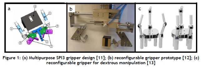
Molfino et al. [11] developed a low-cost reconfigurable gripper for assembly and disassembly tasks; the concept is presented in Figure 1a. The mechanism was specified to grasp both prismatic and cylindrical shapes. Two parallel fingers generated a planar grasp, while the third finger was fixed and allowed cylindrical geometries to be grasped. The gripper had three degrees of freedom. The parallel fingers were actuated by pneumatic cylinders. Ziesmer [12] developed a reconfigurable end-effector, shown in Figure 1b, for in-hand manipulation without finger gaiting or regrasping. The gripping mechanism made use of the concept of a part-finger interface. In this concept the interfaces are modelled as joints, implying that the end-effector and part form a closed-loop mechanism. As a result, the part-finger interface allowed reconfigurability between hard finger contacts and planar contacts. Actuation was provided by two two-position linear actuators.
Makris et al. [13] developed a reconfigurable gripper, shown in Figure 1c, for dextrous manipulation in flexible assembly applications. The aim of the research was to create a gripper that is capable of reconfiguration in order to achieve a wide range of grasping modes. The design consisted of three fingers, with a total of eight degrees of freedom, and was intended for high-speed applications. The gripper had a wide range of grasping modes, including the centripetal grasp, the parallel grasp, and the encompassing and pinching grasp. Each of the fingers was coupled to the output shaft of a driving motor. The fingertips were also motor-driven at the tendons.
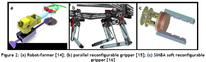
There are limited attempts to merge both cutting and gripping into a single system. Rahman et al. [14] provided an isolated example of a robot-farmer gripping system that also cuts crops; this concept is presented in Figure 2a. The design incorporated a cutter and a two-finger robotic manipulator. The cutter sub-assembly consisted of the cutting blade, blade holder, and gearbox mechanism that allowed the cutter to extend and retract linearly into and out of the holder. The robotic arm sub-assembly consisted of four parts. The two-finger gripper was actuated by a DC servomotor.
Riedel et al. [15] developed a reconfigurable robot that combined a parallel manipulator with an adjustable gripper. The robot was able to grasp objects of various shapes and sizes. It had multiple fingers that could move independently. The robot-object system formed a closed-loop mechanism; the mechanism assumed a kinematic structure similar to that of a parallel manipulator. The robot provided a cost-effective alternative to traditional industrial grippers and fixed architecture parallel manipulators; this concept is presented in Figure 2b. Dottore et al. [16] proposed a tendon-driven modular continuum arm with a soft reconfigurable gripper that was under-actuated, and consisted of four soft fingers linked to an independent actuation module. The gripper fingers were mounted on parallel discs at 180° intervals - i.e., two fingers per disc. The discs were concentric about a centre axis, and a geared DC motor was used to rotate the discs. The fingers were actuated by a tendon-driven mechanism; the cables were actuated by geared DC motors. The concept is presented in Figure 2c.
Cipra et al. [17] developed the HexaMorph, which is a reconfigurable and foldable hexapod robot inspired by the art of origami. The HexaMorph does not have a central body, making it different from most modular robotic systems, which have an open-chain or tree architecture. It has a closed-loop form that permits the robot to envelope itself seamlessly. Since there is no interconnection of modules, the robot reconfigures its orientation by actuating servomotors. The two main methods of reconfigurability for motion are self-deploying and locomotive squirming. The mechanism of reconfigurability can be applied to robot grippers. Locomotive squirming will allow a gripper to change orientation as well as to adapt to different grasp geometries.
2.2 Machine tool: Machining end-effectors
Bologa et al. [18] conducted an investigation using serial industrial robots in CNC milling processes. Point-to-point movements are easily attained by serial robots. Milling processes require accurate control of the entire path; every point on the trajectory must be reached with high accuracy. These intermediate points are calculated using linear and circular interpolation algorithms. Two issues with using serial robots for machining processes are the difficulty of path control and the low rigidity of common serial robotic structures.
Jie and Shu-Hui [19] performed a study on the design of a robotic drill end-effector that was developed to be used in conjunction with a six-axis serial manipulator. The drilling processes generated thrust forces that caused vibrations. The disadvantage of using a serial robot for drilling is its high mechanical compliance, which causes perturbations and deformations in machining applications. To minimise this problem, a mounting platform for the end-effector was developed. The clamping force should be greater than the thrust force in order to stabilise the system.
Karpiel and Petko [20] proposed a mechatronic design of a parallel manipulator for milling. A novel 3-RRPRR parallel manipulator capable of three translational degrees of freedom resulted in high payload capacity, large workspace, and higher speeds. The manipulator design amalgamated the advantages of the Steward-Gough platform and a Delta robot. The end-effector platform had an attachment point for the mounting of milling spindles. The maximum achievable milling force was greater than 100 N, which was sufficient to machine aluminium. The complex control required when machining with parallel manipulators is a challenge.
3 DESIGN OF A RECONFIGURABLE END-EFFECTOR
3.1 System architecture
The end-effector consists of three sub-systems: the machine-tool sub-system for metal cutting, the gripper for material handling, and the reconfiguration sub-system for switching between the functions. An overview of the system architecture is presented in Figure 3. There are five distinct levels of the design. The first level is the attachment surface to the robot through a bolted coupling. The second level is the main platform, upon which the reconfiguration sub-system and spindle sub-system are attached through a bolted coupling. The third level represents a moveable platform to which the gripper sub-system is attached. The gripper fingers are designed to be actuated from the base of each finger mount. The fourth level consists of the gripper fingers and the tendon-driven actuation mechanism. The fifth level represents the gripper palm, which simultaneously functions as a structural part of the reconfiguration mechanism and provides a contact surface for gripping operations.

3.2 Reconfiguration sub-system design
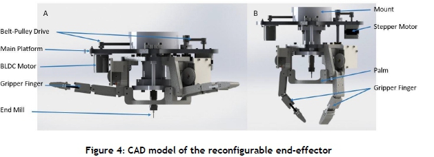
In this design, the spindle is statically mounted onto the main platform, providing maximum stiffness during machining. The machining configuration is shown in Figure 4a. Reconfiguring the end-effector is accomplished by a linear actuated platform that is driven by a lead screw and stepper motor system. The platform is extended toward the work surface, thereby moving the gripper over the spindle to deploy it. The grasping pose is shown in Figure 4b. Moving the gripper over the spindle, as illustrated, mitigates the possibility of the cutting tool damaging parts during handling. Furthermore, power to the machine spindle is disconnected during part handing, allowing for safe part handling. The reconfiguration time is approximately 1.6 seconds; this is the time it takes to deactivate the spindle, move the gripper platform to the grasp position, and activate the motors that drive the fingers. The gripper, linear actuator, and spindle systems were controlled with an Arduino Due microcontroller.
3.3 Machine spindle sub-system design
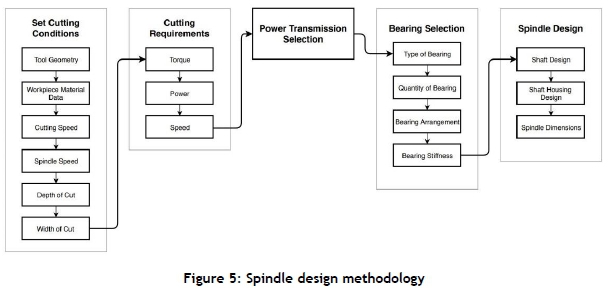
The spindle sub-system was designed for surface contouring and high-speed milling operations, including face, partial face, end, profile, and pocket milling. The compact spindle was designed to mill wood, plastics, and non-ferrous metals such as aluminium, copper, and bronze. Maeda's [21] expert spindle design system was used in conjunction with modal analysis and Finite Element Analysis (FEA) to develop the system. The methodology is presented in Figure 5. Initialisation of the problem yield required cutting conditions. Milling aluminium 6061-T6 with a Cleveland C76050 [22] end mill requires a minimum torque, power, and speed of 0.173 Nm, 219.71 watts, and 12127.61 RPM respectively. These parameters must be met by the designed machine tool. The selection of an angular contact ball bearing for the machine tool is followed by the mechanical design of the spindle shaft and housing.
The machining sub-system consists of a high-speed brushless DC motor, machine spindle, and pulley-belt drive coupling. The NTM Propdrive 3548 brushless DC motor was coupled to the spindle via a pulley-belt drive system. A single row angular contact bearing was placed at the front of the spindle shaft, and a double row angular contact bearing was placed at the rear. Figure 6 presents the components of the spindle design. The high-speed brushless motor was switched on/off and its speed controlled by an ESC and Arduino board.

The machine tool was designed for compatibility with ER11 metric collets. The collet holder is able to clamp an end mill with a maximum diameter of 7 mm. The end-effector can be mounted onto serial robots, parallel robots, and three-axis machines. The design of the unit permits easy adaption to different mounting configurations. Table 1 indicates the specifications of the spindle design.

3.4 Gripper sub-system design
The end-effector required a lightweight gripper mechanism to minimise the mass of the system. A heavy end-effector would compromise a robot's ability to position the end-effector accurately and repeatably. A multi-link tendon-pulley architecture, with an underactuated servomotor drive, was chosen for implementation. The multi-link fingers easily adapt to various geometries, the tendon-pully mechanism allow the design to be compact and lightweight, and the underactuated drive simplifies the control of the mechanism. The end-effector supports a minimum of two modular gripper fingers, which can be increased to a maximum of four fingers, allowing a wide variety of part geometries to be grasped. Tendons are actuated at the base link of each finger by a micro-servomotor and pulley system. A flexible rubber joint allows for the added compliance and dexterity of the gripper. Rouleau's [22] under-actuated gripper design method, presented in Figure 7, was used in this research. There are three design levels, decreasing in significance. The first level requires the input of object geometry and mass; with this data, the required grasp force and torque are determined. The selection of the electric actuator is achieved with gripping requirements. The second level defines the mechanism of actuation. Lastly, a low-level design describes the physical model of the gripper system.

Figure 8 provides a sectional view of a single finger sub-assembly. Each finger consists of three links, two revolute joints, and a flexible end joint. The underactuated design is defined by the double cable systems that are shown. The red cable represents the retraction system; this is coupled to a set of extension springs. The retracted pose of the gripper is a requirement for reconfiguration. The retraction system has five extension springs per finger. The blue cable represents the grasping system, which is coupled to a servomotor via a pulley, as indicated in Figure 8. The servomotor rotates 180 degrees in a clockwise direction, providing a tension force in the cable during a grasping operation. Table 2 indicates the specifications of the gripper sub-system.


4 DYNAMIC PERFORMANCE AND INTERACTIONS - SPINDLE SUB-SYSTEM
4.1 Sub-system integration - experimental cases
Metal cutting mechanics are influenced by tool geometry, the properties of the material being cut, cutter speeds, and feed rates. Spindle dynamics are influenced by the dynamic stiffness of the spindle shaft and its mountings. Reconfigurability further influences spindle dynamics, as additional mechanical elements are present that change the stiffness and mass of the overall system. The integration of machining and part handling into an end-effector required an investigation into the effect of combining these functions in a single device. The performance of the spindle sub-system was therefore investigated at various stages of integration with the reconfiguration and gripper sub-systems. Figure 9 a-d illustrates the cases that were investigated. The mounting of the end-effector must have a high rigidity to attain a fixed boundary condition [28]. The end-effector was therefore mounted onto a steel frame, as illustrated.
4.2 Experimental modal analysis of multistage end-effector assembly
The frequency response functions of the machine tool spindle were computed to determine whether the integration of the gripper sub-assembly and reconfiguration sub-assembly affected the structural dynamic characteristics of the machine tool. According to Grossi et al. [22], machine tool dynamics are usually represented by a frequency response function at the tooltip. The function is generated by conducting an impact test on the stationary tool. Doina [23] researched the dynamic properties of milling centers by experimentation. An impulse force caused excitation in the machine tool, and the vibration response was recorded. Accelerometers were positioned at the spindle head, the table, and the clamping device. The research allowed the determination of the critical frequencies, damping, and stiffness of the system. Shiak and Strinivas [24] investigated the modal characteristics of a spindle tool unit experimentally. Tooltip frequency response and stability lobe diagrams were obtained using the finite element method. The frequency response function of the endmill tool system was also determined experimentally by means of impact hammer testing with a triaxial accelerometer. Input and output signals were recorded, and Fourier transforms obtained the frequency response. The average tooth angle method was used to predict the stability lobes.
In this research, the National Instruments data acquisition device CDAQ-9171 and sound and vibration module NI-9234C were used in conjunction with a Bruel and Kjaer impulse hammer 8206-002 and a uniaxial accelerometer 4507B to perform experimental modal testing. National Instruments Signal Express software was used to compute the fast Fourier transform of the frequency response function. An accelerometer was placed at the tool-tip, and an impulse hammer was used to strike the tooltip.
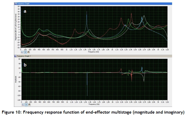
Figure 10 represents the acquired magnitude and imaginary frequency response signals of cases a-d; the white curves correspond to scenario a, the red curves to scenario b, the green curves to scenario c, and the blue curves to scenario d. The inverted peak at 2348.8 Hz from Figure 10.b corresponds to the critical frequency of the system. The natural frequencies of the system are represented by peaks in Figure 10.a. Five such frequencies may be identified. Modal analysis was conducted using the peak-picking method. The critical mode produced the largest amplitude, identified as 2348.8 Hz. A critical amplitude of -0.00138 g/N at this frequency was found from Figure 10.b. The experimental stiffness K_exp and Damping ratio ζ are 27510 N/m and 0.013171 respectively. The cutting stiffness or specific power was calculated using the cutting force coefficients for aluminium 6061-T6. The specific cutting stiffness coefficient K_s was found to be 907.055 N/mm2[26].
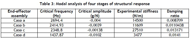
Table 3 summarises the results of the modal analysis. The critical frequency decreased and the damping ratio increased, with decreasing mass. The critical excitation of higher frequencies corresponds to higher critical speeds. This is in accordance with the Rayleigh-Ritz method of critical speed for rotating shafts [27]. Case a, which is the fully assembled end-effector, has the highest critical frequency; the corresponding critical speed is approximately 162 000 rpm. This speed is well above the operating range of the machine tool developed in this research.
4.3 Stability analysis of multistage end-effector assembly
Stable machining produces a high-quality surface finish on parts, and reduces tool wear by keeping vibrations to a minimum. In unstable machining, variations in the magnitude of cutting forces excite the spindle, causing vibrations that lead to changes in the chip thickness. There are many methods of prescribing stable operating conditions in material removal operations. Stability diagrams are used in milling operations; these diagrams take into consideration the properties of the work material and the cutting tool. These diagrams are computed for different tool-workpiece combinations. Stable milling on the reconfigurable end-effector is possible, provided that a stability diagram is used when selecting process parameters.
Many studies have contributed to the advancement of regenerative chatter theory; these include Altintas and Budak [28], Merritt [29], Tlusty [30], and Smith [31]. The theory relates spindle speed to the depth of cut or critical chip width. This generates a stability lobe diagram that allows the selection of the highest stable material removal rate. Tlusty proved that stability is dependent on both machine tool dynamics and cutting force coefficients [28]. Spindle speed affects both cutting force coefficients and the frequency response. The investigation of chatter prediction models has resulted in a chart called a stability lobe diagram (SLD); this chart was used to select stable machining parameters. High-speed milling benefits greatly from an accurate SLD at increased spindle speeds. A greater depth of cuts at faster spindle speeds increases productivity. In this research, cutting force coefficients were referenced from similar studies [28], [29], [30] and [31].
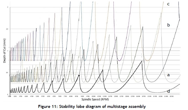
The SLD was generated by means of Altintas's [28] stability equations for multiple linear plots. Yue [31] proposed an iterative approach to the solution of the depth of cut and spindle speed as functions of milling parameters defined by Altintas and Budak's mechanistic force model. Figure 12 presents the SLD for cases a to d, as outlined in Section 4.1. The area under the curves represents the regions of chatter-free cutting conditions. The results show that the region of stability is affected by the additional components of the reconfigurable dual function end-effector.
Comparisons may be drawn, based on the following criteria: limiting depth of cut and horizontal distance between successive 'troughs' and 'crests'. Higher limiting depths of cut are characteristic of high material removal rates; therefore it is advantageous to attain a large value. The distance between successive lobe troughs or lobe crests is indicative of the contained area of the lobe. Larger lobe areas correspond to larger regions of stable cutting conditions, which is advantageous. The limiting depth of cut for case d is the least of the four configurations. The largest depth of cut is attained by assembly case c, as illustrated in Figure 9c. This is attributed to the stiffness of the tool assembly, as presented in Table 3. It is evident that limiting the depth of cut is approximately equivalent for cases a and b - that is, with the fully assembled system and with the gripper sub-system removed. The stable region of case a is larger than that of case b - that is, with the fully assembled system and with the gripper sub-system removed. The results indicate that cutting stability is influenced by the reconfigurable dual-function design; nevertheless, stable cutting is still possible.
5 DYNAMIC INTERACTION - GRIPPER SUB-SYSTEM
5.1 Experimental set-up
The dynamic response of the gripper system was investigated because vibrations were being transmitted from the spindle rotation and cutting process while the gripper was in a retracted state. The purpose of the investigation was to establish whether the dual-purpose end-effector's feasibility would be diminished by unwanted vibrations. The vibration response of the gripper unit was measured by placing one accelerometer on each gripper finger. The following sources of excitation were investigated:
1. Excitation from the free-running machining spindle at various speeds.
2. Excitation from a linear cut into aluminium 6061 at a feed rate of 0.73 mm/sec and a 0.42 mm depth of cut.
The first case provided insight into the idle condition vibrations exhibited by the gripper system, while the second case showed the vibrations exhibited during a typical machining operation. The chosen feed rate was selected, based on the recommended rates for end-milling aluminium 6061 with a two-flute end mill [32]. The maximum depth per pass was set at 0.42 mm, as the machine tool tends to chatter when the depth of cut is excessive. Figure 12a shows the aluminium sample being slot milled. Figure 12b illustrates the finished cut with chips.

5.2 Vibration response of gripper system - free rotating spindle
The machine-tool spindle was run at various speeds with no cutting engagement, and the average vibration response of each gripper finger's distal phalange was measured. The average acceleration-time response is shown in Figure 13.

In the event of an idle spindle, the gripper acceleration response increases with spindle speed, as expected. The maximum average acceleration experienced by the fingers occurs at 11559 RPM. The machine tool vibrated intensely at spindle speeds between 11500 RPM and 11600 RPM, induced by the oscillations created by the GT2 timing belt at these speeds. Spectral analysis was conducted to detect frequencies and amplitudes at various spindle speeds. The highest detected frequencies occurred at 2556 RPM; the average value of this frequency was 530.77 Hz. The largest detected amplitude was found at 14722 RPM, and phase occurred at a rotational speed of 4853 RPM. Noise and vibration levels were tolerable, and the noise level increased as the spindle speed increased. The main source of noise was the spindle belt drive.
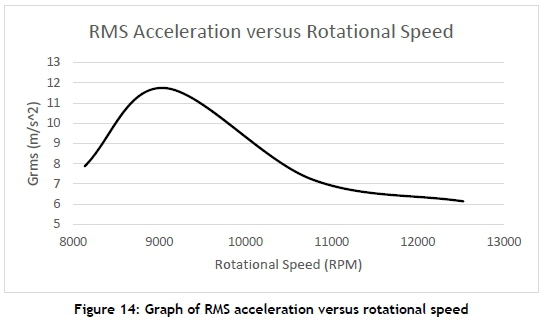
5.3 Vibration response of gripper system - linear cut
The average acceleration-time response for the gripper is shown in Figure 14. The average acceleration response was measured at the fingertip of each gripper finger. The end-milling process produced larger accelerations at lower spindle speeds. The maximum average acceleration experienced by each of the fingers occurred at 9057 RPM. Spectral analysis was conducted to determine the corresponding frequencies and amplitude of each spindle speed. The highest detected frequencies occurred at 12530 RPM; the average value of this frequency was 485.107 Hz. The largest detected amplitude and phase occurred at a rotational speed of 9057 RPM. The vibration characteristics of the disengaged tool and the engaged tool differed. In the first case, when the tool was disengaged, the machine tool maintained a fixed-free boundary condition. This is best described as a vertical cantilever beam, fixed at the top and free at the bottom. In the second case, when the tool was engaged in the workpiece, the machine tool had a transient fixed-fixed boundary condition. This was owing to the lateral support gained from the combined loading that occurred at the tool-tip. The milling forces prevented the free oscillation of the machine tool.
6 GRASP FORCE ANALYSIS
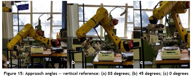
The grasp force of a robot gripper indicates its maximum holding force. The grasping force was determined experimentally at approach angles of 88 degrees, 45 degrees and 0 degrees, as illustrated in Figure 15.
End-effector servomotors were used at maximum torque output. A laboratory scale with a resolution of 0.1 g was used to measure the maximum load at these approach angles. A Fanuc M10IA serial robot was used to position the end-effector in three orientations. Figure 16 illustrates the relationship between the approach angle and the output load generated by the gripper finger. The results indicated that the force was a maximum at a 0° approach angle. As the approach angle increased, the finger force decreased. The force normalised at an approach angle of approximately 78°. The cable drive mechanism transmitted rotational torque from the servomotor output shaft to the proximal phalanx of each finger. Large approach angles decreased the tension force produced by the servomotor in the cable. The gripper produced a larger grasp force for smaller approach angles. Objects that required less angular travel of the gripper finger had a larger grasp force exerted on them. Lower grasp forces were available to objects with a smaller volume.

7 CONCLUSION
The high cost of a traditional CNC machining system has created interest in the use of robots for light machining applications in small- to medium-scale manufacturing enterprises. Industrial grippers are generally used for high repeatability single-purpose tasks. This research has developed a cost-effective compact reconfigurable end-effector that is able to perform both end-milling and part handling operations.
A prototype was designed, constructed, and tested to validate the feasibility and practicality of such an end-effector. The end-effector was a combination of machining, gripping, and reconfiguration sub-systems. To date, the literature has focused on machining stability and part handling as two separate fields of study. In this research, the extent of each sub-system's influence on the other was established, to determine whether the performance of the combined system was lower than that of the individual parts.
Machining produces vibrations during the material removal process. A comparative study was conducted to determine the stability of the machine-tool spindle with and without the gripper and reconfiguration subsystems. Impulse tests were performed to determine the frequency response functions of each assembly. Experimental modal analysis was conducted to determine the modal parameters of each assembly. The results showed that the critical frequency and critical operating speed of the end-effector are highest when the gripper and reconfiguration sub-systems are attached. The damping ratio of each sub-assembly stage indicates that the system is underdamped. The integration of all sub-systems was observed to have a significant effect on the chatter onset frequency.
Stability lobe diagrams were generated for each assembly. The stability lobe diagrams provided useful information about the selection of chatter-free cutting conditions for aluminium 6061-T6. The SLD presented stable cutting regions for each assembly of the end-effector. The results showed that the fully assembled end-effector yielded similar stability lobes to those of the end-effector with the gripper subsystem detached. An identical limiting depth of cut was observed for these two cases. However, the fully assembled reconfigurable end-effector has a broader range of stable depths of cut than when the gripper sub-system is removed. The findings show that the end-effector produced larger stable regions with the gripper sub-system attached. Therefore the stability of the end-effector is increased with the gripper subsystem.
The effect of the machine-tool on the gripper system was investigated. The end-milling operation of an aluminium 6061-T6 sample was conducted at various speeds to determine the average vibration response of the gripper. It was observed that the average vibration of the gripper decreased after 9057 RPM with increasing spindle speed. The results showed that noise and vibrations caused by the metal cutting operation had no significant effect on the gripper sub-system.
A grasp force analysis was conducted on the gripping system. The results showed that the maximum grasp force of each finger occurred at an approach angle of 0°. The maximum grasp force of the mechanism occurs when the finger is parallel to the surface of the geometry. Objects that require minimal angular travel of the gripper finger have an increased grasp force. Objects that require gripper fingers to extend to 88° have a decreased range of grasp force.
The findings that have been presented suggest that the reconfigurable dual-purpose end-effector has the potential to operate successfully. Future research directions include the integration of acceleration and sound sensors with real-time vibration and sound-analysing software. The aim of this signal monitoring system would be to detect the onset of chatter parameters based on the computed stability model. The system should throttle speeds and depths of cut to stable regions.
ACKNOWLEDGEMENTS
The authors would like to thank the National Research Foundation for supporting this research under grant TTK170421228180.
REFERENCES
[1] Bruning, J., Denkena, B., Dittrich, M.-A. & Park, H.-S. 2016. Simulation based planning of machining processes with industrial robots. Procedia Manufacturing, 6, pp. 17-24. [ Links ]
[2] Schneider, U., Poseida, J.R.D., Drust, M. & Verl, A. 2013. Position control of an industrial robot using an optical measurement system for machining purposes. In 11th International Conference on Manufacturing Research (ICMR2013), September 2013, Cranfield University, UK., pp. 307-312. [ Links ]
[3] Schneider, U., Poseida, J.R.D., Drust, M., Verl, A. & Van der Swaag, J. 2014. Combining holistic programming with kinematic parameter optimisation for robot machining. In 45th International Symposium on Robotics (ISR 2014), June 2014, Munich, Germany, pp. 524-530. [ Links ]
[4] Domroes, Rieger, M. & Kuhlenktter, B. 2014. Towards autonomous robot machining. In 45th International Symposium on Robotics (ISR 2014). June 2014. Munich, Germany. pp. 1-6. [ Links ]
[5] Poppeova, V., Uricek, J. & Bulej, V. 2011. Trends in the area of multitasking machine tools. In Katalenic, B., DAAAM International Scientific Book 2011, pp. 227-242. Vienna: DAAAM International. [ Links ]
[6] Olazagoitia, J.L. & Wyatt, S. 2007. New PKM Tricept T9000 and its application to flexible manufacturing at aerospace industry. SAE Technical Paper, 2007-01-3820. [ Links ]
[7] Braumann, J. & Brell-Cokcan, S. 2011. Parametric robot control: Integrated CAD/CAM for architectural design. In Proceedings of the 31st Annual Conference of the Association for Computer Aided Design in Architecture (ACADIA), October 2011. Banff, Alberta. pp. 242-251. [ Links ]
[8] Toolcraft, M. 2014. Milling takes another step away from the human operator, in ETMM, www.etmm-online.com/milling-takes-another-step-away-from-the-human-operator-a-435617/. Georgensgmünd, Germany. p. 60. Cited 10 August 2019. [ Links ]
[9] Yeung, B.H.B. 2000. Development of a 6 DOF reconfigurable gripper for flexible fixtureless assembly, in Graduate Department of Mechanical and Industustrial Engineering. Toronto, Canada: University of Toronto. Master's Theses (2000-). http://tspace.library.utoronto.ca/bitstream/1807/14353/1/MQ54117.pdf. [ Links ]
[10] Tao Zhang, G.S. & Goldberg, K. 1999. Compensatory grasping with the parallel jaw gripper. 4th Workshop on Algorithmic Foundations of Robotics, Oulu, Finland. [ Links ]
[11] Molfino, R., Razzoli, R.P. & Zoppi, M. 2006. A low-cost reconfigurable gripper for assembly and disassembly tasks in white industry, In IFAC Symposium on Robot Control Proceedings Volumes 39.15. Genova, Italy. pp. 498-505. [ Links ]
[12] Ziesmer, J.A. 2009. Reconfigurable end effector allowing for in-hand manipulation without finger gaiting or regrasping, in Faculty of the Graduate School. Milwaukee, Wisconsin: Marquette University. Master's Theses. Paper 2. http://epublications.marquette.edu/theses_open/2. [ Links ]
[13] Spiliotopoulos, J., Michalos, G. & Makris, S. 2018. A reconfigurable gripper for dexterous manipulation in flexible assembly. Inventions, 3(1), pp. 1-15. [ Links ]
[14] Tai, K., El-Sayed, A.-R., Shahriari, M., Biglarbegian, M. & Mahmud, S. 2016. State of the art robotic grippers and applications. MDPI Robotics, 5(2), pp. 1-20. [ Links ]
[15] Riedel, M., Nefzi, M., Hüsing, M. & Corves, B. 2008. An adjustable gripper as a reconfigurable robot with a parallel structure. In Second International Workshop on Fundamental Issues and Future Research Directions for Parallel Mechanisms and Manipulators. Montpellier, France. [ Links ]
[16] Mishra, A.K., Dottore, E.D., Sadeghi, A., Mondini, A. & Mazzolai, B. 2017. SIMBA: Tendon-driven modular continuum arm with soft reconfigurable gripper. Frontiers in Robotics and AI, 4(4), pp. 1-10. [ Links ]
[17] Wei Gao, K.H., Seehra, J.S., Ramani, K. & Cipra, R.J. 2014. Hexamorph: A reconfigurable and foldable hexapod robot inspired by origami. In IEEE/RSJ International Conference on Intelligent Robots and Systems. IEEE: Chicago, IL, USA. [ Links ]
[18] Breaz, R., Bologa, O., Chicea, A.L. & Racz, S.-G. 2015. Using serial industrial robots in cnc milling processes. In Buletinul Institutului Politehnic din lasi. Sectia Constructii de Masini, 61 (3). University of Sibiu, Engineering Faculty: ResearchGate. [ Links ]
[19] Jie, L. & Shu-Hui, J. 2016. The study of design method for robotic drill end effector. In 13th Global Congress on Manufacturing and Management, GCMM 2016. Procedia Engineering, pp. 206-210, Zhengzhou, China: Elsevier Ltd. [ Links ]
[20] Petko, M. & Karpiel, G. 2005. Mechatronic design of a parallel manipulator for milling. In International Conference on Advanced Intelligent Mechatronics. Monterey, California, USA: IEEE, pp. 759-764. [ Links ]
[21] Maeda, O., Cao, Y. & Altintas, Y. 2005. Expert spindle design system. International Journal of Machine Tools & Manufacture, 45, pp. 537-548. [ Links ]
[22] Zoro.com. 2019. Cleveland #C76050 Specifications; Available from: https://www.zoro.com/cleveland-square-end-mill-200mm-milling-dia-c76050/i/G2981373/#specifications. Cited 20 October 2019. [ Links ]
[23] NTM. 2019. NTM Propdrive 3548 characteristic curve. NPC Curve, Editor.http://rcmodelscout.com/Electric-Motors/NTM-Prop-Drive-35-42-Series-1100KV-700W/24367. Cited 15 October 2019. [ Links ]
[24] SDP. 2018 Minimum pulley diameters, M.P. Diameters, Editor.: sdp-si.com. http://sdp-si.com/products/Timing-Belt-Pulleys/index.php. Cited 12 October 2019. [ Links ]
[25] FEETECH. 2019. FEETECH FR0115M product datasheet.. Datasheet, Editor. mantech.co.za. Cited 15 September 2019. [ Links ]
[26] Rubeo, M.A. & Schmitz, T.L. 2016. Mechanistic force model coefficients: A comparison of linear regression and nonlinear optimization. Precision Engineering, 45, pp. 311-321. [ Links ]
[27] Akpobi, J. & Ovuworie, G.C. 2007. Computer-aided design of the critical speed of shafts. Journal of Applied Sciences and Environmental Management, 11(4). pp. 79-86. [ Links ]
[28] Budak, E. & Altintas, Y. 1995. Analytical prediction of stability lobes in milling. Annals of the CIRP, 44(1), pp. 357-362. [ Links ]
[29] Merritt, H.E. 1965. Theory of self-excited machine-tool chatter: Contribution to machine-tool chatter research-1 . Journal of Engineering for Industry, 87(4), pp. 447-454. [ Links ]
[30] Tlusty, J. 1963. The stability of the machine tool against self-excited vibration in machining. Proc. Int. Res. in Production Engineering, Pittsburgh, ASME, pp. 465-474. [ Links ]
[31] Yue, J. 2006. Creating a stability lobe diagram. In Proceedings of the 2006 IJME-INTERTECH Conference. pp. 301 - 350. [ Links ]
[32] Smith, G.T. 2008. Cutting tool technology. London: Springer-Verlag. [ Links ]
Submitted by authors 2 Dec 2019
Accepted for publication 7 Apr 2021
Available online 28 May 2021
* Corresponding author: majestic2020@live.com

