


Services on Demand
Article
 English (pdf)
 Article in xml format
 Article references
Indicators

Related links
-
 Cited by Google
 -
 Similars in Google
Share

 Permalink
South African Journal of Industrial Engineering
On-line version ISSN 2224-7890
Print version ISSN 1012-277X
S. Afr. J. Ind. Eng. vol.31 n.3 Pretoria Nov. 2020
http://dx.doi.org/10.7166/31-3-2449
SPECIAL EDITION
Influence of large artificial porosity on bending behaviour of Ti6Al4V ELI additively manufactured specimens subjected to typical loads during mastication
J.A. WesselsI, #; A. du PlessisII; I. YadroitsavaI; J. ElsIII; I. YadroitsevI
IDepartment of Mechanical and Mechatronic Engineering, Central University of Technology, Free state, South Africa
IIPhysics Department, Stellenbosch University, South Africa
IIICentre of Rapid Prototyping and Manufacturing, Central University of Technology, Free State, South Africa
ABSTRACT
Effective quality control of implants made using additive manufacturing is an important task for suppliers to comply fully with existing regulations and certifications. To study the influence of porosity on the mechanical behaviour of mandibular implants produced by additive manufacturing, preliminary tests with longitudinal flat samples were performed with 3D point bending tests. Ti6Al4V Extra Low Interstitial (ELI) specimens with artificial porosity were designed and subjected to typical loads during mastication. In this work, a finite element simulation was constructed to investigate the bending behaviour of samples, which was consistent with the experimental results. The work shows that even large artificial cavities (designed up to 0.42 mm) do not significantly affect the strength of additively manufactured 2.5 mm-thick Ti6Al4V ELI specimens under typical static loads of mandibular implants, in the considered loading conditions, and for samples subjected to appropriate surface finishing and annealing heat treatment.
OPSOMMING
Doeltreffende kwaliteitsbeheer van inplantate wat met behulp van vinnige prototipering vervaardig word, is belangrik vir verskaffers om die bestaande regulasies en sertifisering volledig na te kom. Om die invloed van porositeit op die meganiese eienskappe van mandibulêre inplantate wat deur prototipering vervaardig word, te bestudeer, is steekproef toetse met plat lengtemonsters deur gebruik van eksperimentele drie punt buig toetse uitgevoer. Ti6Al4V ekstra lae interstisiële monsters met kunsmatige porositeit is ontwerp en onderwerp aan beladings tipies aan die kou proses. Die oprig van numeriese simulasie word in hierdie werk gebruik om die buiggedrag van monsters te ondersoek. Die gedrag stem ooreen met die eksperimentele resultate. Die resultate toon dat groot, kunsmatige holtes (tot 0.42 mm) nie 'n noemenswaardige invloed op die sterkte van toevoegingsvervaardigde, 2.5 mm-dik Ti6Al4V monsters onder tipiese statiese ladings van mandibulêre inplantate, gehad het nie. Die resultate is vergelyk met die vertoning van monsters met behoorlike oppervlak-afwerkings en wat hittebehandelings ondergaan het.
1 INTRODUCTION
Each year millions of patients improve their quality of life through surgical procedures involving implanted medical devices. The benefits of additive manufacturing (AM) in bone reconstruction using metal alloys are unquestionable in terms of customisation of implants and production time, with the main advantage being the patient-specific design capabilities. Despite the enormous contribution that medical devices have made to public health, there is a fear of possible liability exposure in the event of device malfunction or failure. If any defects occur during manufacturing, implant strength will directly influence the part's mechanical properties and performance, leading to the redistribution of stress and changes in displacement, affecting the attached bone tissue and the mineral matrix of the bone, and resulting in implant failure. Based on a comprehensive analysis of the functional anatomy and biomechanics of the human mandible, Ti6Al4V ELI samples were designed and manufactured by Laser Powder Bed Fusion (LPBF). Experiments and numerical simulations of samples with different sizes and placements of artificial pores were done. This approach is a promising method of determining a critical pore-size-to-failure tolerance for AM implants with some defects.
1.1 Mandible biomechanics
The human face is filled with air cavities, soft tissue, arteries, and nerves, and individual variations that need to be considered. Anatomical factors influencing the stability of an implant and screws are bone characteristics (bone density, bone depth, cortical bone thickness), soft tissue, and the proximity of specific anatomical structures (nerves, roots, vessels, nasal cavities). Stress and strain distributions throughout the whole reconstructed implanted part will change; reconstructed implants will thus influence physiological loadings compared with normal situations. Each person's physique and bone structure differs from others, which means that the bite force can vary in both magnitude and direction [1]. Parameters to evaluate in the design are: the flexibility of the reconstructive implant - that is, its capability to absorb the chewing load; and the stress and strain distribution, ensuring that the maximum stresses developed are lower than the yield strength of Ti6AI4V ELI [2].
The human mandible is the only movable stress-bearing bone of the face, and disregarding the forces acting on the mandible can lead to reconstruction failure. The mandible also plays a major role in masticatory and phonetic functions, supporting the teeth, and defining the contour of the lower third of the face. The motion of the mandible during mastication is complex and three-dimensional, which has been described as having the shape of a teardrop [3].Therefore, mandibular discontinuity produces severe cosmetic and functional deformities, including loss of support for the suprahyoid muscles and subsequent airway reduction. Eliminating these severe defects is mandatory in restoring the patient's quality of life.
The mandible, located inferiorly in the facial skeleton, is the largest and strongest bone in the face. When the skull is observed purely as a bony structure, there is nothing anatomically holding the rest of the mandible and the skull together. Four different pairs of muscles on either side of the skull work in combination to pivot the lower jaw up and down, and to allow movement of the jaw from side to side. Loading at different angles are factors that determine mandibular bone structure, since they play an important role in the modelling and remodelling of bone. During biting and mastication, a combination of sagittal bending, corpus rotation, and transverse bending occurs [4]. It is helpful to evaluate the serviceability, performance, and long-term clinical success of biomaterials.
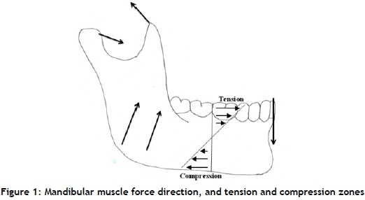
The energy that moves the mandible and allows the functioning of the masticatory system is provided by muscles. Forces applied to the mandible cause various zones of tension and compression (Figure 1), depending on the region where the bite force is applied. The superior portion (top half) of the mandible is designated as the tension zone, and the inferior portion (bottom half) is designated as the compression zone. Loading and contact boundary conditions are described by three main muscular forces during chewing: masseter, medial pterygoid, and temporalis. The mandible is a hoop of bone that deforms with movement, based on the origin and insertion of the muscles of mastication [5]. As indicated by Ledogar et al. [6], the average maximum sustainable biting force that is generated by mastication is about 496-756 N. Model tests of the mastication organ are very often conducted on flat specimens. By reducing the spatial structure to a flat sample, one can assume a symmetrical mandible load with muscle activity and reactions in temporomandibular joints and occlusion force [7].
1.2 Laser powder bed fusion components' porosity
Defects in laser powder bed fusion (LPBF) include unintended porosity, rough surfaces, and deviations from the design, which can have different root causes and can vary significantly between samples. These different types of pore typically have different sizes, shapes, and 3d distributions. All these types of defect affect the mechanical properties of a final part. Random porosity, high surface roughness, and deformation during processing are currently the main drawbacks in LPBF parts. Predicting the defective samples' mechanical properties with numerical simulations is highly important to understanding the effect of these defects. Quality control in metal-based AM is extremely important for the effective control of dimensional inaccuracy, porosity, and other defects that arise during the process [8]. Porosity is a dominant and physical defect; its presence affects the performance of as-built parts, and it is particularly detrimental to mechanical strength and fatigue performance [9]. Lack-of-fusion defects are irregularly shaped, whereas gas entrapment porosity is very spherical. Generally, the average porosity in a part built with good specifications is >99.5 per cent dense, which means 0.5 per cent porosity or less [10-11].
The use of X-ray tomography to visualise porosity in parts - non-destructively and prior to mechanical testing - allows in-depth understanding of the effect on the mechanical properties' capability of the part. This provides the possibility to distinguish critical defects from harmless pores, thus building confidence in AM processes. Knowing the priorities for a part's strength, surface finish, and minimising support material can help to determine the best possible orientation.
2 METHODOLOGY
Finite element simulations were conducted as a frictionless action, although in experimental testing some form of movement between the sample and supports did occur which, in reality, can cause small variations in the deflection and stresses obtained from the numerical simulations and experimental results. The Finite Element Analysis (FEA) loop begins with mesh, loads, boundary conditions, and material properties, which resembled experimental models as closely as possible. Failure location prediction through the numerical simulation of complex geometric shapes serves as a tool for optimising the design of mandibular implants. For numerical simulations of Ti6Al4V, an elastic modulus of 114 GPa was used [12].
Analysis of the porosity and mechanical properties of samples with defects will be compared with standard tested specimen samples and numerical simulations. Experimental data and evaluation by numerical simulation on loading permits the mechanical consequences of defects for manufactured customised mandible implants to be established. ANSYS software was used to construct a virtual simulation of static loading for a three-point bending static-load simulation in order to verify the experimental results.
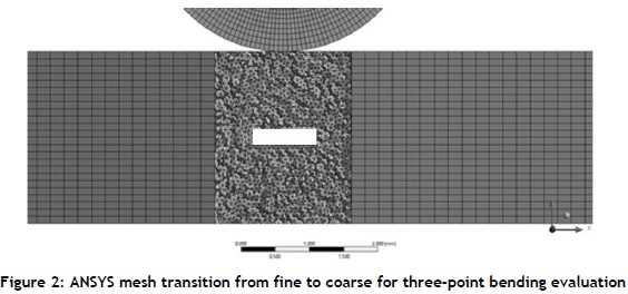
Numerical simulation is extremely important in the validation of experimental results; therefore a fine mesh is recommended that is at least 10 times smaller than the designed pore for optimal result validation. When a geometric part is meshed, it is decomposed (breaks down) into a series of finite elements. It is important that the elements of the mesh conform well to the geometry of the part, thus representing a good approximation of the part's geometry. Tetrahedral meshing is highly automated, and is good at predicting stresses with sufficient mesh refinement [13]. A coarse mesh requires fewer computational resources to solve and, while it may give very inaccurate solutions, it can be used as a rough verification. Using mid-side nodes as the default setting, the stresses at the boundary of a hole/defect are more accurately resolved. This meshing strategy will still re-mesh the entire model with the objective of reducing the error in the region of interest. Adaptive mesh refinement could be generated in regions where the geometry requires a finer mesh in order to represent the defect accurately, which will provide a more accurate solution. The mesh transitions from a fine tetrahedral mesh size 70 urn around the designed artificial defects to a coarse hex dominant mesh of 200 um for the rest of the remaining sample (Figure 2).
Since the 3D distribution, size, and shape of all defects are known from micro-CT scans, it is useful to predict the effect of the observed pores on the mechanical properties of the part [14-15]. Spatial pore distribution and high stress bearing points were examined and incorporated into samples of Ti6Al4V ELI for review. Previous research [16] found that a defect of 200 μm had no significant effect on the tensile properties of the LPBF Ti6Al4V ELI samples under quasi-static loading. It was also shown that a layer-induced defect of 180 μm thickness had partial areas fused together [12]. Therefore, in the present study, artificial defect thickness was increased to 210 μm and 420 μm respectively.
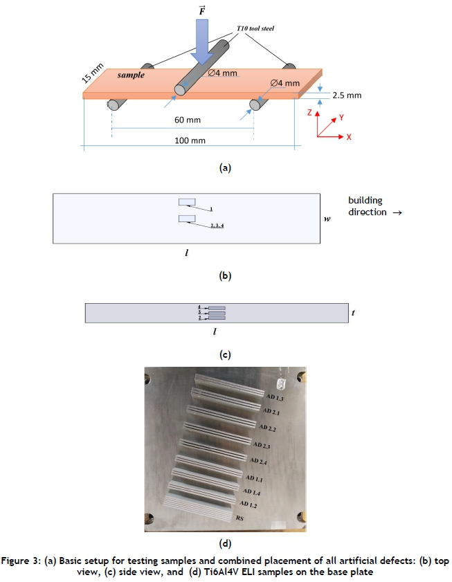
Three-point bending (TPB) is one of the most common material testing methods to study the mechanical performance of materials with structural applications. For this flexural loading, all three fundamental stresses are present (tensile, compressive, and shear). Bending tests were done perpendicular to the specimen, simulating a vertical downwards bite force. Three-point bending is preferred to allow the sample to move freely at the supports when loaded; this method is used to simulate a mandibular implant. The tool and support radii were 2 mm (Figure 3a). The contact area of the tool radius was enough to keep sharp edges from creating a fracture within the samples, and large enough to simulate an area of mandibular teeth biting down. For the experimental bending force, relative span length (supports), sample area, and the punch radius were kept constant for all samples. Based on the anatomy literature, a suitable sample size of 100 mm x 15 mm x 2.5 mm (Figures 3a,b) was used with a maximum simulated bite force of 1 kN and an experimental load force of 800 N - 1.5 kN. The induced artificial defects (AD) were fabricated by leaving cavities in the CAD file. The artificial defects in the sample thickness were set in the centre, 2 mm from the side and 500 μm from the top and bottom respectively, representing the four independent cases shown in Figures 3b and c, and in Table 1. The artificial defects were much larger than typical random LPBF object porosity. The designed defect size was 1000 μm x 300 μm x 210 μm (set AD1 ), and 1000 μm x 500 μm x 420 μm (set AD2) to ensure that results were obtained for a worst case scenario LPBF mandibular implant. Samples from set A were subjected to 900 N loading, set B to 1.5 kN, and set C to 800 N (see Table 1 ).
Reference solid samples (RS) and samples with defects were manufactured by EOSINT M280 at 30 |im layer thickness, as prescribed by EOS optimal process parameters. The samples were manufactured vertically, along a 15 mm side (15 mm build height) (Figures 3b, d).
The LPBF Ti6Al4V samples were stress relieved in a vacuum atmosphere for three hours at 650°C and furnace cooled, then annealed at 941 °C for two hours and furnace cooled. For certified implants, post-printing treatment is incredibly important. The annealing stage alters the physical, and sometimes the chemical, properties of a material to increase ductility and to reduce its hardening, allowing for a long-lasting implant.
The as-built samples were rough because the tested surface was created in layers, since they were manufactured in the vertical direction (Figure 3d). The as-built samples had a roughness of Ra=18±2.0 μm and Rz=102±9.6 μm. Surface finishing was done by shot peening in a blast cabinet with a 6 mm diameter blasting nozzle and stainless steel beads that were accelerated under a pressure of 3.7 bar. Shot peening was applied for about 10 minutes per surface. The size of the stainless steel beads was near 500 μm. After shot peening, the surface roughness had been improved: Ra = 5±0.8 μm and Rz = 34±4.8 μm. As expected, the shot peening reduced the surface roughness significantly.
The samples from Set A (900 N loading) were CT scanned at the University of Stellenbosch CT scanner facility using a General Electric Nanotom S system set to optimum parameters. Nano-CT scan settings of 150 kV, 130 μA, with a 0.5 mm beam filter were used, with image acquisition of 500 ms per image and 3 000 step positions in a full 360° rotation. At each step position, the first image was discarded, and the two subsequent images were averaged. The samples were scanned at 10 urn. Visualisation and analysis were performed by Volume Graphics VGStudioMax 3.3 software [8].
3 RESULTS
Von Mises stress was used to predict the yielding of the materials under complex loading. If the sample is to remain elastic under loading, then the maximum value of the Von Mises stress from the FEA model needs to remain below the yield value. Figure 4 shows the maximum Von Mises stress obtained from simulations of samples with artificial defects (AD) and the reference sample (RS). Artificial defects 0.5 mm from the surface showed the highest stress (AD1.4 and AD2.4). At some location along the thickness of the beam, the stress was minimal; this location was the centroid or neutral axis of the cross-section.
FEA analysis showed that, when a load of 1 kN was applied, the maximum Von Mises stress exceeded the point of yield stress for all the samples (Figure 4a) - that is, 800-880 MPa in annealed LPBF Ti6Al4V material [16] (Figure 4a). There was minimal Von Mises stress in the solid sample, and a maximal value was found in samples with pores closer to the top surface (sets AD1.4 and AD2.4). Sharp corners in designed voids had an additional detrimental effect on the mechanical performance of the parts, as can be seen in Figure 4b, where a high stress area is indicated by a black arrow.
3.1 Porosity analysis
The reference sample showed 99.99 per cent density by X-ray tomography. Careful micro-CT analysis showed that most of the estimated pores had elongated shapes, and the pores were small and randomly distributed in the sample (Figure 5). The largest pore - 135 μm in diameter - was elongated parallel with the building direction owing to a possible lack of fusion. Therefore <0.01 per cent porosity was calculated before bending. After bending, the biggest pore was 171 μm in diameter. The defect volume ratio was 0.0015 per cent before bending and 0.0019 per cent after bending. The number of pores was found to be near 500 in both cases, indicating that no new defects were noted by the CT scanning after the bending tests had been conducted (Figure 5). It is becoming increasingly clear that small pores will always be present in LPBF parts, varying in distribution and morphology depending on the system used, the powder used, and the process parameter. Very often smaller pores have no influence on the mechanical properties of a part. Larger pores, on the other hand, start to play a significant role, affecting the mechanical properties and leading to premature failure.
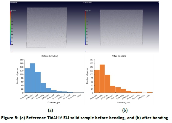
Analysing the samples pre- and post-bending, similar results were obtained. One remark that arose from the sample's integrity is that smaller defects form around the artificial defects. Pores along the top and bottom surfaces (from the loading direction) after bending were noted, but the distribution of the pores by size looked very similar before and after bending.
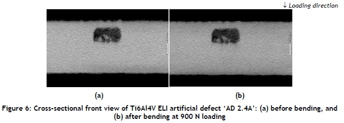
Sintered Ti6Al4V ELI powder was visible inside the artificial pores after heat treatment (Figure 6). During annealing, the loose powder fused together, causing necking. Pores were fairly irregularly shaped compared with the sharp rectangular edges in the designed and simulated defects. The CT scans did not reveal deformation, cracks, or changes in the pores' shape after loading at 900 N - i.e., in set A (Figure 6). Optical microscope photos of etched cross-sectioning of samples from set B also did not show any cracks around the artificial defects (Figure 7), nor at the surrounding material. Samples from set C tested at 800 N did not show any plastic deformations.
3.2 Experimental stress and strain behaviour
In three-point bending tests, fractures are assumed to occur at the midpoint between the supports, which may not be exactly true [17]. This statement may depend on any internal or external defects that create notches that alter the mechanical integrity of the specimen so causing more stresses to focus on this area. The major concern is whether fracture could occur at the interface between the stacked layers around the artificial defect. In the bending test, the loading head pressed against the top surface. The experimental results of the Ti6Al4V samples were plotted on load-crosshead graphs indicating failure when subjected to different loading forces and different internal geometric anomalies. This verification method allows the simulation of defects in a controlled environment, and answering related questions about whether a certain size defect will impact the performance of a mandibular implant. Experimental tests were used as a baseline, and to validate the correctness of FEA. It was found that, with an increase in punch radius, the elastic modulus, peak load, and contact length also increased [18]. Note that only the crosshead motion was taken into account for the stress-strain calculations. As recommended in the literature, the strains determined using the crosshead displacement need to be considered, and should only be used for qualitative purposes [19]. Owing to the mastication force (756 N), an over-estimation of experimental loading (800 N, 900 N, and 1.5 kN) for the samples showed exceptional results, even when the area of the artificial defects was higher than most literature experiments conducted in the past. Looking at the integrity of the reference samples, they should be produced so that all data to any required point should be identical, with no delamination observed before reaching the required load. The experimental results show that the samples had similar stress-strain behaviour in bending tests up to 800 N loading for sets A, B, and C, and up to 900 N for samples from sets A and B. Up to a load of 900 N, no difference in stress-strain behaviour was noted for all samples from sets A and B, whether or not they had artificial defects (Figure 8).
Samples from Set B and the reference sample were tested until plastic deformation. This was used as a guide, or to superimpose samples with internal artificial defects leading to non-uniform curvature. It was noted that samples with internal defects closer to the point of contact experienced'higher stresses. It was also noted that samples with an artificial defect size 1000 μm x 500 μm x 420 u.m close to the loading surface (AD2) revealed the same result within the elastic range when subjected to a 900 N and a 1.5 kN force. Set B samples subjected to a 1.5 kN force showed no visible fractures or failure; they were plastically deformed.
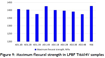
On closer inspection, the samples tested at 1.5 kN loading force indicated yielding up to 950 N loading (Figure 8). The curve was divided into a first region, linear in appearance, which explained the elastic deformation of the material. The deformation also represented whether the displacement of the indenter was affected in the upper surface, owing to the presence of some imperfections on the surface of the laminate. The second region after the load reached a peak value, gradually decreasing in load and increasing in displacement, owing to its reaching the material's yield point. No sudden drop in load indicated zero fractures, and eventually led to complete sample failure. A maximal flexural strength of 1375 MPa to 1425 MPa (Figure 9) was found. The lowest values were found in sample AD 2.4, as predicted by FEA. Samples with big pores were filled with sintered powder owing to annealing, giving additional strength to the tested samples.
4 CONCLUSION
Complex shape production in LPBF often results in porosity near critical load-bearing sections; careful anatomical inputs were thus included in both experimental and numerical assessments for future encounters with implants having possible defects. Artificial defects were designed and induced in Ti6Al4V ELI LPBF samples. Ti6Al4V ELI sintered powder was found inside designed voids owing to annealing heat treatment. Pores were fairly rounded in shape, compared with the sharp rectangular edges in the simulated defects. The results indicated that defects of 1000 μm x 300 μm x 210 μm and 1000 μm x 500 μm x 420 μm at various depths to the neutral axis had no significant outcome on the mechanical performance of the samples with a thickness of 2.5 mm when tested statically in three-point bending. Most importantly, they could all reach the maximum predicted mandibular bite force without failure. It must be mentioned that cyclic loading tests are also required in future work, as fatigue failure is often initiated at the pores, which requires further investigation.
ACKNOWLEDGMENT
This work was supported by the South African Research Chairs Initiative of the Department of Science and Technology and the National Research Foundation of South Africa (Grant Ne97994) and the Collaborative Programme in Additive Manufacturing (Contract N?CSIR-NLC-CPAM-15-MOA-CUT-01).
ORCID® identifiers
J.A. Wessels: https://orcid.org/0000-0002-7274-1428
A. du Plessis: https://orcid.org/0000-0002-4370-8661
I. Yadroitsava: https://orcid.org/0000-0003-3132-5724
J. Els: https://orcid.org/0000-0002-4837-8892
I. Yadroitsev1: https://orcid.org/0000-0002-7556-8675
REFERENCES
[1] Baek, S.H., Cha, H.S., Cha, J.Y. & Moon, Y.S. 2012. Three-dimensional finite element analysis of the deformation of the human mandible: A preliminary study from the perspective of orthodontic mini-implant stability. Korean Journal of Orthodontics, 42(4), pp. 159-168. [ Links ]
[2] Al-Ahmari, A., Nasr, E.A., Moiduddin, K., Anwar, S., Al Kindi, M. & Kamrani, A. 2015. A comparative study on the customized design of mandibular reconstruction plates using finite element method. Advances in Mechanical Engineering, 7(7), pp. 1-11. [ Links ]
[3] Koolstra, J.H. 2002. Dynamics of the human masticatory system. Critical Reviews in Oral Biology & Medicine, 13(4), pp. 366-376. [ Links ]
[4] Levrini, L., Paracchini, L., Mangano, C., Pisani, L. & Caprioglio, A. 2015. Evaluation of biomechanical effects of interocclusal surfaces on the mandible. South European Journal of Orthodontics and Dentofacial Research, 2(2), pp. 27-34. [ Links ]
[5] Markad, N. 2014. Mandible fractures. Available at: https://www.slideshare.net/nsavenature/mandible-fracture-symposium-march13. Accessed: 30 Nov 2018. [ Links ]
[6] Ledogar, J.A., Dechow, P.C., Wang, Q., Gharpure, P.H., Gordon, A.D., Baab, K.L., Smith, A.L., Weber, G.W., Grosse, I.R., Ross, C.F., Richmond, B.G., Wright, B.W., Byron, C., Wroe, S. & Strait, D.S. 2016. Human feeding biomechanics: Performance, variation, and functional constraints. PeerJ., 4, e2242. doi:10.7717/peerj.2242. [ Links ]
[7] Kijak, E., Margielewicz, J., Gaska, D., Lietz-Kijak, D. & Wiçckiewicz, W. 2015. Identification of mastication organ muscle forces in the biocybernetic perspective. Biomed. Res. Int., 2015(436595). doi:10.1155/2015/436595. [ Links ]
[8] Du Plessis, A., Le Roux, S.G., Booysen, G. & Els, J. 2016. Quality control of a laser additive manufactured medical implant by X-ray tomography. 3D Printing and Additive Manufacturing, 3(3), pp. 175-182. [ Links ]
[9] Wycisk, E., Solbach, A., Siddique, S., Herzog, D., Walther, F. & Emmelmann, C. 2014. Effects of defects in laser additive manufactured Ti-6Al-4V on fatigue properties. Physics Procedia, 56, pp. 371-378. [ Links ]
[10] Vandenbroucke, B. & Kruth, J.P. 2007. Selective laser melting of biocompatible metals for rapid manufacturing of medical parts. Rapid Prototyping Journal, 13(4), pp. 96-203. [ Links ]
[11] Du Plessis, A., Le Roux, S.G., Booysen, G. & Els, J. 2016. Directionality of cavities and porosity formation in powder-bed laser additive manufacturing of metal components investigated using X-ray tomography. 3D Printing and Additive Manufacturing, 3(1), pp. 48-55. [ Links ]
[12] MatWeb. n.d. Titanium Ti-6Al-4V ELI (Grade 23), annealed. Available online: www.matweb.com. Accessed: 30 Nov. 2019. [ Links ]
[13] Srinivas, K. 2017. Abaqus - Tips and tricks Vol 1. Available at: https://www.advanses.com/abaqus-tips-and-tricks-vol-1. Accessed: 30 Nov 2019. [ Links ]
[14] Du Plessis, A., Yadroitsava, I., Le Roux, S.G., Yadroitsev, I., Fieres, J., Reinhart, C.H. & Rossouw, P. 2017. Prediction of mechanical performance of Ti6Al4V cast alloy based on microCT-based load simulation. Journal of Alloys and Compounds, 724, pp. 267-274. [ Links ]
[15] Weiler, J.P., Wood, J.T., Klassen, R.J., Maire, E., Berkmortel, R. & Wang, G. 2005. Relationship between internal porosity and fracture strength of die-cast magnesium AM60B 333 alloy. Materials Science and Engineering: A, 395(1), pp. 315-322. [ Links ]
[16] Yadroitsev, I., Krakhmalev, P., Yadroitsava, I. & Du Plessis, A. 2018. Qualification of Ti6Al4V ELI alloy produced by laser powder bed fusion for biomedical applications. The Journal of the Minerals, Metals & Materials Society (TMS), 70(3), pp. 372-377. [ Links ]
[17] Albert, C., Jameson, J.R. & Harris, G.F. 2012. Design and validation of bending test method for characterization of miniature pediatric cortical bone specimens. Journal of Engineering in Medicine, 227(2), pp. 105-113. [ Links ]
[18] Hou, P., Zhao, H., Ma, Z., Zhang, S., Li, J., Dong, X., Sun, Y. & Zhu, Z. 2016. Influence of punch radius on elastic modulus of three-point bending tests. Advances in Mechanical Engineering, 8(5), pp. 1-8. [ Links ]
[19] Broughton, W. 2012. Testing the mechanical, thermal and chemical properties of adhesives for marine environments. In: Weitzenböck, J. (ed.), Adhesives in marine engineering. Cambridge: Woodhead Publishing, pp. 99-154. [ Links ]
# The author was enrolled for an MEng degree in the Department of Mechanical and Mechatronic Engineering, Central University of Technology, Free State, South Africa
* Corresponding author: johanadriaanwessels@gmail.com

