


Services on Demand
Article
 English (pdf)
 Article in xml format
 Article references
Indicators

Related links
-
 Cited by Google
 -
 Similars in Google
Share

 Permalink
South African Journal of Industrial Engineering
On-line version ISSN 2224-7890
Print version ISSN 1012-277X
S. Afr. J. Ind. Eng. vol.31 n.3 Pretoria Nov. 2020
http://dx.doi.org/10.7166/31-3-2448
SPECIAL EDITION
System development for the five-axis extrusion of a photopolymer
D.M. KirkmanI, #; A.F. van der MerweI, *; R.I. CampbellII
IDepartment of Industrial Engineering, Stellenbosch University, South Africa
IISchool of Design and Creative Arts, Loughborough University, United Kingdom
ABSTRACT
The development of a novel method of additive manufacturing involving the support-free extrusion of a photopolymer is discussed. The objectives of the paper are the presentation of mechanical and electrical hardware developments for a freeform additive manufacturing system, a discussion of the process developments that have taken place, and the presentation of the results from tests used to validate improvements to the system. Developments include the replacement of the UV light source with lasers, and the implementation of collision avoidance algorithms. The results include a significant increase in the speed of the extrusion process, and an improved toolpath viability achieved by the implementation of the collision avoidance algorithms.
OPSOMMING
Die ontwikkeling van 'n nuwe toevoegingsvervaardigingmetode vir die ondersteuninglose ekstrusie van 'n fotopolimeer word bespreek. Die doel is om die meganiese en elektroniese hardeware vir die vormvrye toevoegingsvervaardigingstelsel aan te bied, om die ontwikkeling daarvan te bespreek, en om toetsresultate, wat die verbeteringe valideer, voor te hou. Die ontwikkeling sluit die vervanging van die ultravioletligbron met lasers, en die skepping van algoritmes om botsings te vermy, in. Die resultate dui op n noemenswaardige toename in die spoed van die uitpersingsproses en n verbeterde werktuigroete deur die toepassing van die botsingvermyding algoritme.
1 INTRODUCTION
Methods of additive manufacturing (AM) allow for far greater geometric complexity than conventional manufacturing methods such as injection moulding [1], [2]. However, the layer-based nature of most AM processes exhibits several innate drawbacks. These include long manufacturing times as a result of the time-consuming process of depositing successive layers [3]; mechanical anisotropy resulting from weaknesses in the bonding of material between successive layers [4]; and the need for support structures, which further increases manufacturing time [5] and results in increased material use and cost [6], [7]. These drawbacks, among others, limit the application of polymer AM for the production of end-use parts in a manufacturing environment [8], [9].
This paper presents developments in previous research [10]. By examining the extrusion of material in 3D space without the need for support structures, the study aims to prove that the freeform extrusion of a photopolymer could be developed as an alternative to layer-based AM processes for the manufacture of load-bearing components. The three objectives for this paper are as follows:
1. Presentation of mechanical hardware developments in the extrusion system.
2. Discussion of process developments, with a focus on toolpath planning algorithms.
3. Presentation and discussion of tests performed to validate the above-mentioned system developments.
The section that follows provides the background to the study, after which details relating to the above three objectives are discussed. Finally, a discussion is presented based on the results of the testing, and conclusions are drawn by comparing the outcomes of testing with the aim of the study.
2 BACKGROUND
Several studies involving the freeform AM of polymers are discussed as the background to the study.
A 2014 study conducted by the Joris Laarman Laboratory developed a method for the freeform extrusion of a two-part thermosetting plastic using five-axis toolpaths implemented with a robotic arm [11]. Although the extrusion process was relatively slow with a maximum deposition speed of 3.3 mm/s, the project successfully demonstrated the freeform extrusion of a polymer without the need for support material. The use of 'inclination control' in relaxing the nozzle tangency constraint was found to be useful in avoiding collisions and in reducing the dexterity required of the robotic arm in executing complex toolpaths.
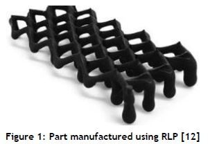
Another approach to support-free AM is the method of rapid liquid printing (RLP) developed by the MIT self-assembly laboratory during 2017 [12]. RLP makes use of a gel as a supporting medium, into which material is extruded using a peristaltic pump. Three-axis toolpaths are executed using a robotic arm. A wide range of materials has been used successfully in manufacturing freeform geometries, including urethane rubbers, acrylics, and epoxies. This process offers significant advantages over the process developed by Laarman et al. [11], both in terms of speed (deposition speeds reached 1 m/s) and the fact that no build platform is required. The successful execution of freeform toolpaths using only three axes would also result in significantly simpler toolpath generation procedures than those required in the study by Laarman et al. [11]. Figure 1 shows a part manufactured using RLP.
Chen, Zhou and Lao [13] developed a process of selectively curing a photosensitive resin in a vat using a UV light source as the curing tool. A five-axis computer numerical control machine was used in executing the toolpaths. Although freeform toolpaths were successfully implemented, support structures were required as a result of the forces generated by the adhesion of the curing tool to the cured resin in the vat.
Several processes have been developed for the AM of freeform microstructures for applications in micro-electromechanical systems. Solvent-cast direct-write (SC-DW) 3D printing involves the extrusion of a polymer dissolved in a volatile solvent. Guo et al [14] used PLA dissolved in dichloromethane, with freeform toolpaths implemented using a three-axis robot. Extensive experimentation on geometric retention of the material after extrusion indicated that freeform extrusions could only be achieved when using nozzle diameters below 150 um [15]. A similar study by Farahani, Lebel and Therriault [16] investigated the process parameters required for the UV-assisted 3D microprinting of a photocurable gel. A high-viscosity gel with shear-thinning behaviour was used. Shear thinning of the gel enabled extrusion at relatively low pressures, and resulted in increased geometric retention on exiting the extruder nozzle and before being cured. UV LEDs were used as the curing light source, and a three-axis robot was used to implement the toolpaths. A nozzle diameter of 150 um was used. Figure 2 shows helical samples manufactured using this method.

Several concepts from the above studies were used in the development of a freeform photopolymer extrusion method, which is discussed in depth below.
3 SYSTEM DEVELOPMENT
An overview of the system first presented by Kirkman et al. [10] is required before discussing further developments.
The system that was developed by Kirkman et al. [10] consisted of a stationary extruder mounted in the vertical orientation. An extrusion bed was mounted on a Motoman SDA-10D six-axis robotic arm for the execution of five-axis toolpaths. The stationary extruder configuration was chosen to limit sagging of the extruded segment owing to gravity before curing could occur. A UV-curable gel was selected as a material, which allowed for rapid and controllable curing using UV LEDs mounted on the extruder. The material consisted of a standard stereolithography resin with fumed silica added in a mass ratio of about five per cent, resulting in a gel that exhibited shear-thinning behaviour. Instead of using pneumatic-based extruders as implemented by Guo et al. [14] and Farahani et al. [16], a mechanical syringe-based extruder was designed, using a stepper motor to power a linear actuator, which allowed for accurate control of the gel flow rate. The extruder was controlled by using an Arduino Uno, where the extrusion flow rate and activation of the UV LEDs was determined by the state of universal outputs set by the Motoman robot controller. Figure 3 below shows the extrusion of a straight-line segment.

MATLAB was used to generate the toolpaths; the geometry point data for each extrusion path was imported from an Excel file and converted to a series of tool definitions defined by the position of each successive geometry point relative to the extrusion bed, and by the posture of a line joining each point to the next point. 'Start tools' and 'end tools' were used in defining moves between the toolpaths of individual segments. By incrementally redefining the tool definition and specifying the move of each new tool to the nozzle exit point, complex calculations to define the pose of the robot end-effector at each step in the extrusion process were circumvented. Tool definitions were used to write job files (in the form of JBI text files) to be uploaded to the robot controller. The job files included extruder control commands using the robot universal outputs to synchronise the robot and the extruder control.
The first iteration of the extrusion system successfully demonstrated the freeform extrusion of a photopolymer using a nozzle diameter of 3 mm. However, several issues and limitations were observed, as summarised below:
1. The extrusion process was relatively slow, with a maximum speed of 1.5 mm/s being demonstrated.
2. A plastic nozzle tip, as seen in Figure 3, had to be attached to the nozzle to shadow the nozzle exit to prevent nozzle blockage owing to resin curing at the nozzle tip. This plastic tip drastically increased the collision potential of the nozzle.
3. Extrusions were of a constant diameter equal to the nozzle diameter.
4. The reflectivity of the melamine extrusion bed resulted in frequent nozzle blockages owing to resin curing in the nozzle from the UV light reflected off the extrusion bed.
5. The simultaneous extrusion and curing of resin for horizontal extrusions on the extrusion bed was not possible, again owing to nozzle blockages.
6. Collision avoidance was lacking, both in the mechanical design and in the toolpath planning. Collisions of the extruder LED mounting with the extruder bed, and of the extruder nozzle with previously extruded segments, were observed.
The hardware developments and the development of the extrusion process that were undertaken to address the above issues are presented in the following sections.
3.1 Hardware development
The first two issues above were mitigated by replacing the UV LEDs with laser diodes, which provided a more focused and intense light source. This resulted in an increase in the curing rate of the gel, which facilitated higher extrusion speeds. Also, the plastic nozzle tip mentioned above could be removed, since the lasers could be focused in the region directly below the nozzle exit without causing incidental UV radiation on the nozzle itself.
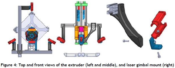
Three 5 mW lasers with a wavelength of 405 nm were used. The lasers were mounted on the extruder frame using gimbal mountings, as shown in Figure 4 below. The laser spot size could be adjusted using the screw-mounted aperture on each laser. Since minimal spreading of light from the laser diodes was observed, the lasers could be mounted further from the nozzle than was the case for the UV LEDs. This position adjustment, along with the removal of the nozzle tip, helped to mitigate issue 6 above from a mechanical perspective, since collisions of the extrusion bed with the light source were avoided, and the chance of collisions of the nozzle with previously extruded segments was reduced. The improvements in extrusion speed, which were facilitated by the implementation of lasers, are discussed in the experimentation section.
Issue 4 above was solved by replacing the extrusion bed surface with sand-blasted glass. This material was chosen owing to its high diffractivity. Testing confirmed that nozzle blockage when the nozzle and bed were in close proximity was no longer observed.
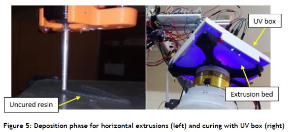
Issue 5 was solved by using a UV box for the separate curing of horizontal segments. In this case, gel would be deposited by the extruder without activating the UV lasers. The bed would then be moved to the UV box where curing was performed using LEDs. Nozzle blockage during horizontal extrusion was completely avoided using this strategy; and the UV box could also be used for the post-curing of extruded parts. Figure 5 below shows the extruder with the UV box attached.
3.2 Extrusion process development
Concurrent with the implementation of hardware upgrades, improvements were made to the MATLAB toolpath planning and generation algorithms to increase the functionality of the system and the range of viable toolpaths. These improvements are discussed below.
3.2.1 Improvements in single-segment extrusions
Several changes were implemented to improve the quality of the single-segment extrusions. The extrusion of each segment was divided into three phases: initiation, extrusion, and termination. As discussed previously by Kirkman et al. [10], initiation consisted of priming and 'lights-off' extrusion. Parameters for determining the priming distance and the height above which the lasers would be activated were retained. Passive inclination control for limiting bed tilt during the extrusion phase was also retained. For the termination phase, retraction of the extruder had not previously been implemented, and this resulted in the gel oozing after the extruder had been deactivated. A retraction distance, or distance of extrusion with diameter equal to the nozzle diameter, was introduced as a new parameter that was implemented by activating the extruder in reverse until the specified distance had been traversed by the linear actuator. Minor hardware adjustments were required to allow for the effective retraction of the extruder, and several tests were performed to determine a suitable retraction distance. Retraction resulted in a significant improvement in the termination phase for each segment, and also improved the quality of horizontal segments. The priming distance for each segment subsequent to the implementation of retraction took into account the retraction distance that had to be re-traced by the linear actuator before priming could begin.
Issue 3 above was addressed by making small control adjustments to the system. Initially the extrusion diameter was kept equal to the nozzle diameter by matching the extrusion flow rate with the robot tool speed, where the tool speed specified the speed of the segment being extruded at the point where the segment met the nozzle exit. The restriction to constant diameters limited the geometric freedom offered by the system. To extrude variable diameters, one of two approaches could be used: either the tool speed could be changed while keeping the extruder flow rate constant; or the extruder flow rate could be adjusted while keeping the tool speed constant. The first option was selected, as this made it possible to maintain control over the gel curing rate, and simplified the control of the extruder, since the extrusion flow rate would remain constant while extruding a range of diameters. For each geometry point used as input to the MATLAB toolpath generation algorithm, a diameter tag was added. The equation below was used to determine the tool speed for each move, by equating the extruder flow rate within and outside the nozzle.

In Equation 1 above, vgelcorresponds to the flow velocity of the gel within the nozzle. Dtoolis the diameter of the extrusion outside the nozzle exit, and vtoolis the necessary robot tool speed to ensure that the desired diameter was obtained while using a constant extruder flow rate. Figure 6 below illustrates the above variables, and shows examples of samples extruded using the above approach.
The range of feasible diameters that were demonstrated during testing is discussed in the experimentation section.
3.2.2 Toolpath planning for multiple-segment extrusions
Toolpath planning became necessary when the toolpath generation algorithm was expanded to allow for the extrusion of multiple segments within a single build. Path planning was divided into two levels. Level 1 dealt with the order in which segments would be extruded, both to minimise the chance of collisions and to ensure that segments that formed the initiation point for other segments would be extruded first. Level 2 path planning then dealt with the determination of nozzle posture during the extrusion of each segment to minimise the chance of collision between the nozzle and previously extruded segments.
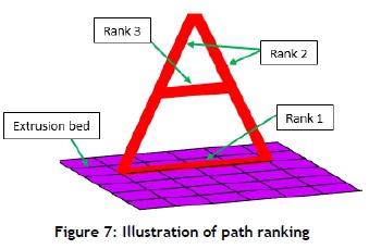
Level 1 path planning made use of a ranking system, with the ranks being allocated as follows:
Rank 1: Segment is horizontal and extruded onto the extrusion platform.
Rank 2: Segment starts on the platform and is not horizontal.
Rank 3: Extrusion starts from another segment (above the extrusion platform).
The ranking system assumed that each non-horizontal segment was either monotonically increasing or decreasing; segments with a turning point were sub-divided into two segments at the turning point. An illustration of the path ranking is shown in Figure 7 below.
Segments were ordered in increasing rank. Once all horizontal segments had been extruded (without activation of the lasers), the bed would be moved to the UV box for curing, and ranks 2 or 3 would then be extruded. If two or more segments had the same rank, the order of execution would be determined by the order of the placement of the respective geometry data sets in the Excel data file imported by the MATLAB toolpath planning code. Although this ranking system was very primitive, it laid the foundation for the automatic ordering of toolpaths for more complex builds.
Level 2 path planning required a more complex approach to ensure that each path was collision-free. This level was further sub-divided into three phases, based on the portion of the toolpath being executed. The approach phase consisted of the toolpath moves required to move the bed into position beneath the nozzle before beginning the extrusion. The extrusion phase consisted of all the toolpath moves during which the extruder was activated. Finally, the bed retraction phase consisted of the moves in which the extrusion was moved away from the nozzle after the termination of the segment. Initially, the focus of the collision avoidance algorithms lay on the extrusion phase, since the chance of collision during the approach and bed retraction phases was considered to be low.
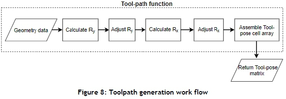
Prior to the development of approaches for collision avoidance, it was necessary to develop an intuitive method of adjusting the angle of the nozzle relative to the extrusion bed and relative to the segment being extruded. Initially, the 'current' and 'next' points of the toolpath data set were used to define the posture of each tool, where each successive tool would line up with the nozzle during extrusion. Two angles were used in defining the posture of each tool: Ryand Rx. These angles defined the intrinsic rotations of the bed coordinate system required to line up with the tool coordinate system, and were used by the robot controller in determining tool posture. These angles were initially used to implement the passive inclination control by reducing their values to relax the tangency constraints of the extrusion with the nozzle, as discussed in Kirkman et al. [10] and illustrated in Figure 8 below. However, the intrinsic nature of these angles made it difficult to develop an intuitive approach to directly manipulate the angle of the nozzle relative to the extrusion.
An alternative approach was thus developed, as it would be more intuitive to consider a system in which the extrusion bed is stationary and the nozzle executes the toolpath, instead of directly manipulating the bed tilt in an effort to avoid collisions. Using this approach, the position of the nozzle relative to the bed was calculated, and adjusted if necessary, using a path planning algorithm prior to the calculation of the toolpaths.
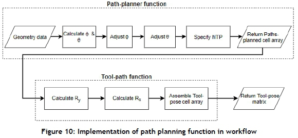
First, spherical coordinates were used to define the position of each point x + 1 in the geometry data set relative to point x. The line joining these two points would define the posture of the nozzle relative to the bed, if tangency between the nozzle and extrusion were maintained. This posture was defined using the <p and 6 angles, as shown in Figure 9. These angles could be adjusted, resulting in φ and 0 , thus providing an intuitive way of adjusting the position of the nozzle relative to the bed. The position of the adjusted nozzle top point (NTP) relative to the tool centre point (TCP) would then be used in the calculation of the Ryand Rxangles for each tool definition.

The adjustment of the NTP position using the < and 6 angles was used in the collision avoidance algorithms that were implemented in the path planning function, resulting in an adjusted work-flow, as shown in Figure 10.
Once the above work-flow was established, it was possible to develop collision avoidance algorithms. Toolpath moves were regarded as moves of the nozzle relative to a horizontal bed as a result of the approach discussed above.
As a starting point for collision avoidance in the extrusion phase, only collisions between the extruder nozzle and previously extruded segments at joins between the current segment and previous segments were considered. It was anticipated that this approach would deal with the larger portion of collisions during the extrusion phase while being computationally economical. An algorithm to identify possible collisions was then developed. This algorithm simply checked the location of all the endpoints of previously extruded segments of ranks 2 or 3, and compared these locations with the locations of all geometry data points along the current segment. If any of the measured distances were less than a threshold distance, a collision point would be recorded. The algorithm developed to avoid collisions between the nozzle and the identified collision points is presented below. Initially, only the φ angle has been used in manipulating the nozzle posture, with the manipulation of 0 being left for further study.
1. Specify a minimum allowable clearance distance dclearancebetween the nozzle centreline and a collision point.
2. Specify a lower limit φlimon the value that the angle φ may assume in orienting the nozzle away from a collision point.
3. Specify a value φ;ncremen£that defines the amount by which φ is incremented at each iteration of the inclination control algorithm.
4. Start with the first geometry point, x = 1.
5. Calculate the shortest distance dcoUfrom the nozzle centreline to the collision point(s) along the extrusion path.
6. If dcoll < dclearanceand cf> > φllm, then the nozzle centreline is too close to a collision point and should be moved towards the vertical. Set φ = φ - φncrement, calculate the location of the adjusted NTP, and return to step 5. Else proceed to step 7.
7. The nozzle centreline is either sufficiently far from the collision point(s) or the value of φ has reached φiim. Collision avoidance has been completed for point x. If x is less than the total number of points in the path, set x = x + 1 and return to step 5. Else proceed to step 8.
8. Return the adjusted NTP coordinates for each point along the current path.
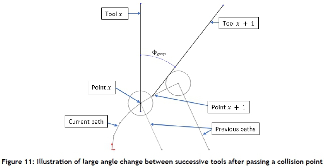
The above algorithm essentially increased the angle of the nozzle relative to the extrusion platform, ensuring that the nozzle cleared any endpoints of previous extrusions. Once the nozzle entered the clearance zone defined by dclearance, its posture was fixed by φlimto avoid excessively large angles between the nozzle and the current segment. A 'relaxation' algorithm was then implemented for the toolpath moves immediately following a collision point, to ensure a smooth transition between tool postures and to avoid a large angle change between successive tools, as illustrated in Figure 11.
In order to test the collision avoidance algorithms offline, an animation function was developed using MATLAB. This function enabled the visualisation of the nozzle trajectories. Each category of toolpath move was recorded using a different color, allowing for a quick analysis of toolpaths prior to execution using the extrusion system. The output of the animation function is illustrated in Figure 12 below.

4 EXPERIMENTATION
Testing to validate developments in the system is ongoing, with the results of tests being used to develop a process parameter map and to validate the collision avoidance algorithms presented below.
4.1 Development of process parameter map
The two critical variables for the extrusion of simple segments were identified as speed and diameter. Speed was specified as the flow velocity of resin within the nozzle, and hence reflected the gel flow rate, which in turn indicated the rate of exposure per unit volume of the gel to the light source. The speed specification was thus important in determining the rate of the curing and geometric retention of the resin. Diameter also had an effect on the degree of curing, since larger diameters would require larger UV penetration depths for complete curing to occur.
A series of tests was set up to determine suitable diameter and extrusion speed parameters for the system. Test samples consisted of straight-line segments of 25 mm length, which were extruded vertically. Diameters were adjusted up and down from the nozzle diameter of 3.0 mm in increments of 0.5 mm, and speed was increased in increments of 1 mm/s starting from 0.5 mm/s. Test samples were analysed for the degree of curing at the surface of the extrusion before post-curing (assessed by touch), uniformity of diameter along the test sample, and the average diameter of the sample compared with the desired diameter. A map indicating the degree of surface curing is shown in Figure 13. The degree of surface curing was theorised to indicate not only the geometry retention, which should improve for more complete curing, but also the strength of subsequent joins to segments, where joins made on segments with more uncured material were thought to be stronger owing to improved cross-linking between segments. The latter theory relating to oxygen-inhibition and joint strength is yet to be tested.
Samples with a diameter below 1.5 mm could not be extruded at the desired diameters, and samples above 5.0 mm in diameter were significantly deformed when considering both cross-section and average diameter. As the extrusion speed increased, it was observed that the degree of curing of the inner portion of the cross-section of samples decreased progressively, resulting in a cylindrical shell of cured resin surrounding the uncured interior. However, samples of acceptable quality could still be extruded and post-cured, even if only thin side-walls formed. As the speed was increased beyond 17.5 mm/s, the thinning side-walls began to rupture, resulting in the uncured resin leaking from the interior.
Diameter measurements showed that the resulting diameter of the samples was within five per cent of the desired diameter for all cases. The uniformity of cross-sections decreased below speeds of 1.5 mm/s, with the cross-sectional shape tending to be triangular - presumably as a result of using three lasers for curing. Extrusion speeds exceeding 1.5 mm/s were thus selected in future tests. However, speeds exceeding 3.5 mm/s were not practical when implementing complex toolpaths, since the rotational speed limits of the robot joints would be reached. The robotic system was thus identified as the limiting factor affecting extrusion speed, except for extrusions requiring exceptional geometric retention and thus low extrusion speeds to ensure maximum curing.
4.2 Assessment of nozzle tangency relaxation on extrusion quality
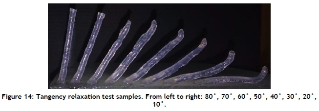
Collision avoidance required that the tangency constraint of the nozzle relative to the extrusion be relaxed. A series of tests was performed to assess the effect of this tangency relaxation on extrusion quality. Samples were prepared with angles ranging from 80° to 10° relative to the extrusion bed, and were extruded with the bed horizontal (perpendicular to the nozzle centreline). The 80° case would be equivalent to a deviation angle of 10° between the vertical nozzle and the extrusion. Samples extruded at a speed of 3.5 mm/s are shown below.
The 50° and 40° samples above showed finning on the upper edges, presumably owing to the edge of the extrusion passing out of the laser focal area, which was located directly beneath the nozzle exit. The remainder of the samples showed finning on the lower edge. Sagging of the segments was first noticeable for the 50° samples, and became progressively worse as the angle of overhang increased. Owing to both the finning and the sagging observations, it was noted that the angle of the extrusion relative to the nozzle should not exceed 30° if geometric accuracy was to be preserved.
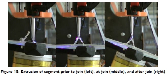
4.3 Execution of toolpaths requiring collision avoidance
Finally, a set of tests was done to assess the collision avoidance algorithms discussed above. A simple test part was prepared that would require the avoidance of a single collision and relaxation after the collision. Figure 15 shows the collision-free joining process.
5 DISCUSSION
The mechanical adjustments to the system resulted in significant improvements in speed and in the ability to extrude horizontal segments. The collision potential of the extrusion head was also reduced by the replacement of UV LEDs with lasers as the curing light source. The issue of nozzle blockage, frequently encountered when using LEDs as a light source, was not encountered when using suitably focused lasers.
The implementation of lasers significantly increased the speed at which segments could be extruded, and speed testing indicated that the robotic system was the limiting factor in determining build speeds, owing to rotational speed limitations observed for more complex extrusions. However, the relationship between geometric retention and extrusion speed for more freeform structures that require a greater degree of geometric retention, such as a helix, has not yet been tested.
Process parameter tests successfully validated the extrusion of segments with diameters deviating from the nozzle diameter. During these tests it was observed that it would be more practical to extrude diameters only equal to or larger than the nozzle diameter from a collision avoidance perspective. Extruding diameters lower than the nozzle diameter would increase the chance of interference between the nozzle and the existing segments.
The joint test shown in Figure 15 successfully validated the collision avoidance algorithms discussed in Section 3.2.2, with a collision-free join being created between two segments. A potential issue observed in this and similar experiments is the blockage of one or more of the lasers by existing segments, which could result in incomplete laser coverage of the segment being extruded.
6 CONCLUSIONS AND FUTURE WORK
Mechanical and process improvements to the system first introduced by Kirkman et al. [10] were presented. These improvements resulted in an increased extrusion speed, diameter range, and reliability of the system. Path planning and collision avoidance algorithms also improved the range of viable toolpaths, with the collision-free extrusion of two individual segments being demonstrated.
Future work includes further experimentation with light sources to improve the uniformity of light coverage, as well as testing the extrusion speed and diameter for freeform structures such as a helix. Smaller nozzle diameters will be tested, as well as approaches for extruding parallel bonded segments. The collision avoidance algorithms will also be developed further to allow for more complex builds.
ORCID® identifiers
D.M. Kirkman: https://orcid.org/0000-0002-2359-8821
A.F. van der Merwe: https://orcid.org/0000-0002-0688-1254
R.I. Campbell: https://orcid.org/0000-0001-6622-673X
REFERENCES
[1] Ngo, T.D., Kashani, A., Imbalzano, G., Nguyen, K.T.Q. & Hui, D. 2018. Additive manufacturing (3D printing): A review of materials, methods, applications and challenges. Compos. Part B Eng., 143, pp. 172-196. https://doi.org/10.1016/j.compositesb.2018.02.012. [ Links ]
[2] Chacón, J.M., Caminero, M.A., García-Plaza, E. & Núhez, P.J. 2017. Additive manufacturing of PLA structures using fused deposition modelling: Effect of process parameters on mechanical properties and their optimal selection. Mater. Des., 124, pp. 143-157. https://doi.org/10.1016/j.matdes.2017.03.065. [ Links ]
[3] Janusziewicz, R., Rolland, J.P., Tumbleston, J.R., Ermoshkin, N., Kelly, D., Johnson, A.R., Pinschmidt, R., Shirvanyants, D., Ermoshkin, A., DeSimone, J.M., Chen, K. & Samulski, E.T. 2015. Continuous liquid interface production of 3D objects. Science, 347(6228), pp. 1349-1352. https://doi.org/10.1126/science.aaa2397. [ Links ]
[4] Dizon, J.R.C., Espera, A.H., Chen, Q. & Advincula, R.C. 2018. Mechanical characterization of 3D-printed polymers. Addit. Manuf., 20, pp. 44-67. https://doi.org/10.1016/j.addma.2017.12.002. [ Links ]
[5] Wulle, F., Coupek, D., Schaffner, F., Verl, A., Oberhofer, F. & Maier, T. 2017. Workpiece and machine design in additive manufacturing for multi-axis fused deposition modeling. Procedia CIRP, 60, pp. 229-234. https://doi.org/10.1016/j.procir.2017.01.046. [ Links ]
[6] Jiang, J., Xu, X. & Stringer, J. 2018. Support structures for additive manufacturing: A review. J. Manuf. Mater. Process., 2(64). https://doi.org/10.3390/jmmp2040064. [ Links ]
[7] Vanek, J., Galicia, J.A.G. & Benes, B. 2014. Clever support: Efficient support structure generation for digital fabrication. Computer Graphics Forum: Segmentation and Structure, 33(5), pp. 117-125. https://doi.org/10.1111/cgf.12437. [ Links ]
[8] Rankouhi, B., Javadpour, S., Delfanian, F. & Letcher, T. 2016. Failure analysis and mechanical characterization of 3D printed ABS with respect to layer thickness and orientation. J. Fail. Anal. Prev., 16, pp. 467-481. https://doi.org/10.1007/s11668-016-0113-2. [ Links ]
[9] Zeltmann, S.E., Gupta, N., Tsoutsos, N.G., Maniatakos, M., Rajendran, J. & Karri, R. 2016. Manufacturing and security challenges in 3D printing. JOM., 68, pp. 1872-1881. https://doi.org/10.1007/s11837-016-1937-7. [ Links ]
[10] Kirkman, D.M., Van der Merwe, A.F. & Campbell, R.I. 2019. Development of a method of additive manufacturing by material extrusion along three-dimensional curves. South African J. Ind. Eng., 30, pp. 9-20. https://doi.org/10.7166/30-3-2264. [ Links ]
[11] Laarman, J., Jokic, S., Novikov, P., Fraguada, L.E. & Markopoulo, A. 2014. Anti-gravity additive manufacturing. In Fabricate 2014: Negotiating Design & Making, UCL Press, pp. 191-197. [ Links ]
[12] Hajash, K., Sparrman, B., Guberan, C., Laucks, J. & Tibbits, S. 2017. Large-scale rapid liquid printing. 3D Print. Addit. Manuf., 4, pp. 123-131. https://doi.org/10.1089/3dp.2017.0037. [ Links ]
[13] Chen, Y., Zhou, C. & Lao, J. 2011. A layerless additive manufacturing process based on CNC accumulation. Rapid Prototyp. J., 3, pp. 218-227. https://doi.org/10.1108/13552541111124806. [ Links ]
[14] Guo, S.Z., Gosselin, F., Guerin, N., Lanouette, A.M., Heuzey, M.C. & Therriault, D. 2013. Solvent-cast three-dimensional printing of multifunctional microsystems. Small, 9(24), pp. 4118-4122. https://doi.org/10.1002/smll.201300975. [ Links ]
[15] Guo, S.Z., Heuzey, M.C. & Therriault, D. 2014. Properties of polylactide inks for solvent-cast printing of three-dimensional freeform microstructures. Langmuir, 30, pp. 1142-1150. https://doi.org/10.1021/la4036425. [ Links ]
[16] Farahani, R.D., Lebel, L.L. & Therriault, D. 2014. Processing parameters investigation for the fabrication of self-supported and freeform polymeric microstructures using ultraviolet-assisted three-dimensional printing. Journal of Micromechanics and Microengineering, 24(5), pp. 1-12. https://doi.org/10.1088/0960-1317/24/5Z055020. [ Links ]
# The author was enrolled for an M Eng (Industrial) degree in the Department of Industrial Engineering, Stellenbosch University, South Africa
* Corresponding author: andrevdm@sun.ac.za

