


Services on Demand
Article
 English (pdf)
 Article in xml format
 Article references
Indicators

Related links
-
 Cited by Google
 -
 Similars in Google
Share

 Permalink
South African Journal of Industrial Engineering
On-line version ISSN 2224-7890
Print version ISSN 1012-277X
S. Afr. J. Ind. Eng. vol.30 n.3 Pretoria Nov. 2019
http://dx.doi.org/10.7166/30-3-2263
SPECIAL EDITION
Cost-effectiveness of Direct Metal Laser Sintered Maraging Steel Inserts for Plastic Injection Moulding Process
J. Combrinck*; B. van As; G.J. Booysen; D.J. de Beer
Department of Mechanical & Mechatronic Engineering, Central University of Technology, Free State, South Africa
ABSTRACT
This paper describes an investigation into the possible heat transfer benefits of conformal cooling channels using maraging steel MS1 inserts, which could result in a reduction of cycle times and cost per product, and improve part quality by eliminating defects such as warpage and heat sinks. A manufacturing cost and lead-time comparison showed that a conventionally manufactured insert reached its break-even point after fewer injection moulding cycles than an additive manufactured insert, due to its lower manufacturing costs. During high-volume production, the additive manufactured insert becomes more profitable to use, due to its shorter cycle times.
OPSOMMING
Hierdie artikel beskryf 'n ondersoek na die moontlike hitteoordrag voordele van vormgetroue verkoelingskanale in martensities-verouderde MS1 insetsels. Dit kan lei tot 'n vermindering in die siklusstye en koste per produk, asook 'n verbetering in die kwaliteit van die vervaardigde komponente deur defekte soos kromtrekking en hitteputte te voorkom. 'n Vergelyking tussen die vervaardigings-koste en -tyd het getoon dat 'n konvensionele vervaardigde insetsel die gelykbreekpunt bereik het na minder spuitgietsiklusse in vergelyking met 'n laag vervaardigde invoegsel vanweë die laer vervaardigingskoste. Tydens hoë volume produksie word die laag-vervaardigde insetsel egter meer winsgewend om te gebruik as gevolg van 'n korter spuitgietsiklus.
1 INTRODUCTION
Product development is the process of designing, creating, and marketing new products for potential customers. The complete process of developing new products is filled with uncertainties, and the risks involved are substantial; but a quick response to market demand is vital to remain competitive [1]. As the lifecycles of modern products decrease, it is important to introduce new products quicker and more efficiently to the market.
Nearly all mass-produced plastic products are formed using dies and moulds [2]. The injection moulding process is one of the most popular methods used to produce complex products in large quantities [3]. Manufacturing injection moulds (IM) can be a time-consuming and extremely expensive process [4]. By increasing the complexity of an IM, mould-manufacturing lead times and costs increase, resulting in many plastic product developments not being commercialised due to the high associated costs. The rate at which IM products can be produced is determined by the rate at which the thermoplastic material can be solidified inside the IM [5]. The time needed to cool down and solidify the product can take up to 70 per cent of the total time needed to produce the product. If the heat transfer efficiency is increased in the IM process, then the rate of production will increase, and thus reduce the product manufacturing costs [6]. The more efficiently heat is transferred from the molten plastic to the cooling medium of the mould, the more efficient the IM cycle becomes [7].
The introduction of additive manufacturing (AM) technologies that are suitable for tooling applications, such as rapid tooling (RT) technologies, gives mould designers more freedom. Traditional tool manufacturing methods can occur in parallel with RT techniques to reduce tooling manufacturing costs and lead-times. RT using AM technologies can produce IM inserts with complex geometries that are difficult, or even impossible, to manufacture with conventional tooling methods. This can be done in parallel with conventional tooling methods that are used to manufacture less complex geometries of the mould. Through AM inserts, conformal cooling channels can be manufactured that conform to the product geometry, which can reduce the cycle time in an IM process while simultaneously increasing part quality by eliminating warpage and other defects by means of a uniform heat transfer from the product [8, 9].
AM technologies and materials have improved during the last few years, and it is now possible to produce IM inserts that are suitable for high-volume injection moulding applications. Maraging steel MS1 by Electro Optical Systems (EOS) is an example of a recent powder development that is suitable to produce tooling inserts for high-volume IM applications [10]. The mechanical properties of maraging steel MS1, combined with the advantages that the direct metal laser sintering (DMLS) process offers, result in mould inserts that are suitable for high-volume production applications for the IM process [5]. While this technique makes it possible to perform high volume production runs, the DMLS process is still considered expensive [11].
Some of the material properties of maraging steel MS1 are summarised in Table 1.
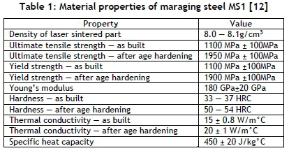
This paper investigates the possible heat transfer benefits of conformal cooling channels using maraging steel MS1 and whether a DMLS insert with conformal cooling channels justifies the higher cost, compared with a conventionally manufactured insert, using computer aided engineering (CAE) and computational flow dynamics (CFD) simulation software.
2 METHODOLOGY
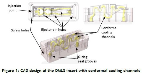
AM inserts with conformal cooling channels and conventionally manufactured inserts with conventional cooling channels were designed for an industrial application. The AM inserts with conformal cooling channels shown in Figure 1 were manufactured through the DMLS process using maraging steel MS1 material.
A conventionally manufactured insert, shown in Figure 2, was designed, considering the limitations of conventional manufacturing techniques, such as straight-line drilling and slotting.
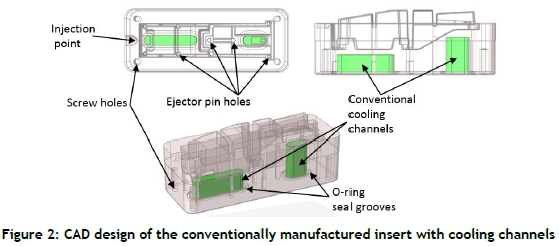
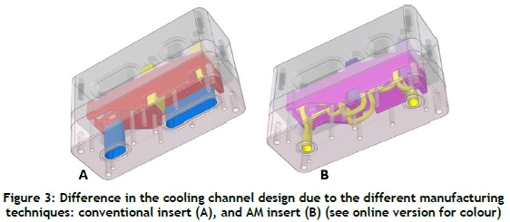
Figure 3 shows the influence of the different manufacturing techniques on the design of the cooling channels. Features such as ejector pins and screw holes influenced the cooling channel design of the conventional insert, whereas the design freedom of AM allowed the cooling channels of the AM insert to follow the contours of the product more closely.
Both cooling channel designs (conformal and conventional) were compared using simulation software ANSYS® and SIGMASOFT®. The mould temperature, water temperature, and water turbulence kinetic energy were simulated with ANSYS® CFD using a steady-state simulation with a constant part wall temperature of 250°C, while SIGMASOFT® mould flow simulation software was used to simulate the IM process.
3 RESULTS AND DISCUSSION
3.1 Heat transfer and flow comparisons
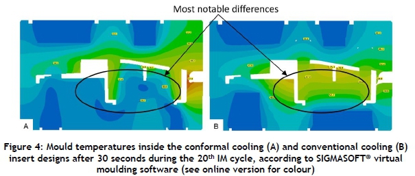
Figure 4 below shows centre-section views of both designs during the IM process indicating how the heat was transferred from the injected molten plastic through the inserts to the cooling medium. The encircled regions of Figure 4 indicate a noticeable temperature difference inside the conformal and conventional cooling channel inserts after 30 seconds into the 20th IM cycle.
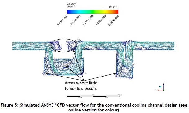
Figure 5 shows a centre-section view of the conventional cooling channel design with flow vectors inside the cooling channels indicating the flow direction and velocity of the cooling water through the channel. Areas where there is no flow are shown in dark blue, while areas with higher flow are shown in yellow and red.
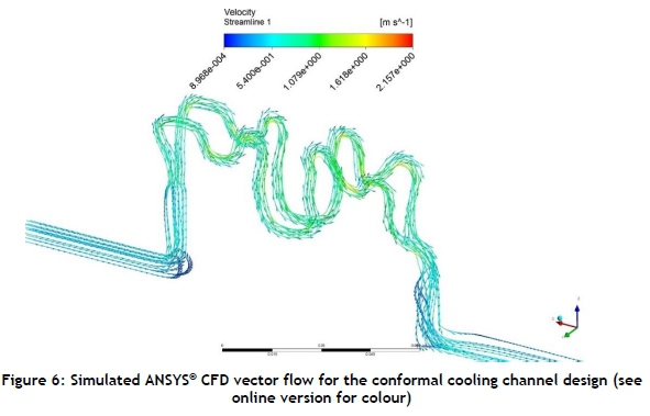
Figure 6 shows a centre-section view of the conformal cooling channel design. The flow vectors have higher velocities and improved directed flow through the channels, as shown by the green and yellow vectors.
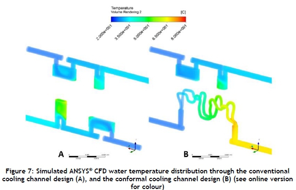
Figure 7 shows the simulated water temperature distribution through the cooling channels of the conventional and conformal cooling channel inserts.
It is evident that the conformal cooling channel, shown in Figure 7 (B), had a larger water temperature difference from the inlet to the outlet, compared with the conventional cooling channel design (A). Thus the rate of heat transferred from the plastic melt through the insert to the cooling medium was greater in the conformal cooling channel design, compared with the conventional cooling channel design, resulting in a faster production rate.
3.1.1 Discussion of results
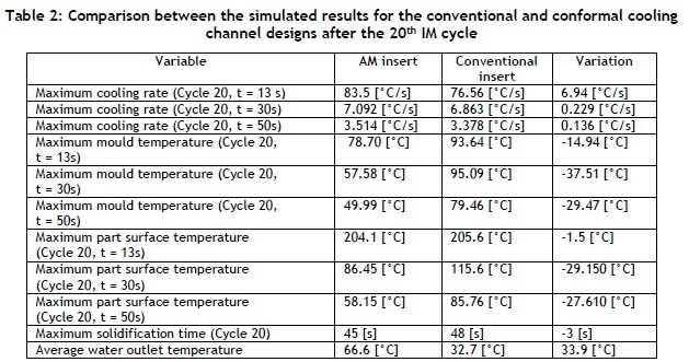
The simulated results shown in Table 2 compared the 20th IM cycle of the conformal and the conventional cooling channel designs, after the mould inserts had reached a quasi-equilibrium thermal state. Three intervals (13, 30, and 50 seconds) throughout the 20th IM cycle were used to record the data below.
From Table 2, it can be concluded that the conformal cooling channel design improved the cooling rate and reduced the mould temperatures, especially in regions that conventional cooling channels cannot reach, as shown by the maximum part surface temperature differences (29.15°C during the 20th IM cycle after 30 seconds into the cycle). This local area cooling resulted in a decrease in the overall cycle time by three seconds, due to the shorter solidification time of the product produced from the AM insert.
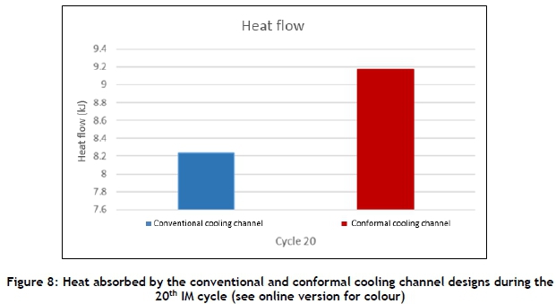
From the simulation results, it was evident that there were regions in the conventional cooling channel design where no flow occurred, resulting in a reduction of heat transfer. The conformal cooling channel design caused a forced directional flow that did not result in stationary water inside the channels. Due to the forced directional flow, the heat transfer rate for the conformal cooling channels was greater than for the conventional cooling channels, as shown in Figure 8.
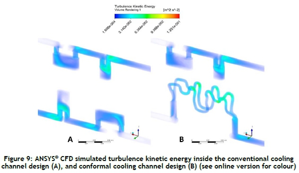
Figure 9 shows that the turbulence kinetic energy inside the conformal cooling channel design was higher around corners, compared with the flow in the conventional cooling channels. In some regions, the flow inside the conformal cooling channel was less turbulent than in certain regions in the conventional cooling channels. This was due to the discontinued curve inside the conventional cooling channel design from the sudden changes in flow direction. The discontinued curve of the conventional cooling channel also resulted in areas of the cooling channel where little to no flow occurred. This was less effective in removing heat from the mould than the continuous curve of the conformal cooling channel. While the continuous curve of the conformal cooling channel also induces turbulent flow, it did not have any regions where low velocities in the flow occurred. It is also evident that the turbulence in the conformal cooling channel was achieved throughout most of the channel, and not only in local regions, as simulated in the conventional cooling channel.
There was a significant difference between the simulated water outlet temperature of the conventional and conformal cooling channel designs. The average outlet temperature for the conventional cooling channel was 32.7°C, compared with 66.7°C for the conformal cooling channel, using a constant heat source during the ANSYS® CFD flow simulation. In practice, these temperature differences would be smaller because the molten polymer cools down due to the heat absorbed by the mould and cooling channels. But the simulation still illustrates the difference between the heat absorption of the conventional and conformal cooling channel designs. The cycle time recorded during actual IM trials was 40 seconds, compared with the 44 seconds simulated by SIGMASOFT®. The difference in the cycle times could be because the IM machine setter was able to optimise the IM process, whereas the results of the simulation were dependent on assumptions and theory that could not account for all 'real world' scenarios.
3.2 Manufacturing cost and lead-time comparison
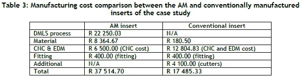
A manufacturing cost and lead-time comparison was conducted between the AM and conventional manufactured inserts. Table 3 shows the comparison between the manufacturing costs of the AM and the conventionally manufactured inserts for the case study described in Section 2.
The manufacturing time for the conventional insert, from design to the finished insert, ready for production, was five days. This included computer numerical-controlled (CNC) programming, CNC machine setup, electric discharge machining (EDM), CNC machining, and fitting the insert into the IM. The total manufacturing time for the AM insert was eight days. This included machine setup, DMLS time, post-processing time (EDM and CNC machining), and fitting into the IM. Although the AM process has a longer manufacturing lead-time, it could be manufactured concurrently with the conventional mould manufacturing processes.
3.2.1 Production costs of IM inserts and break-even analysis
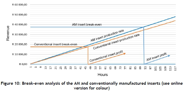
The simulation software measured a difference of three seconds in cycle time between the AM and conventional inserts. The effect of the reduction in cycle time during production was analysed, and is shown in Figure 10 below.
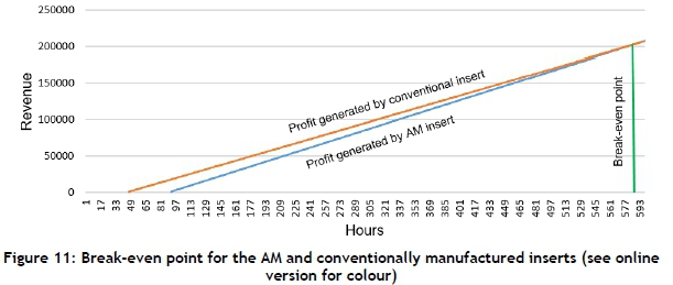
Break-even points and profit generated were calculated to obtain an indication of when it is viable to use DMLS inserts. With an assumed selling profit of R5 per product, a cycle-time saving of three seconds per cycle results in R375 profit per hour for the conventionally manufactured insert, compared with the R409.09 profit per hour for the conformal cooling channel insert. The difference in the profit that could be generated equates to R34.09 per hour. Figure 11 below shows the faster production rate of the AM insert (R34.09 per hour) with a steeper slope, compared with the conventional insert's production rate.
After 92 hours of production, the cost of the AM insert was recovered and it started to generate a return in profit. During this time, the conventional insert had already recovered its investment cost (after 47 hours) and generated a profit of R17 250.00. After 586 hours of production, the increased production rate of the AM insert exceeded that of the conventional insert's production. From this time on during production, one can capitalise using the AM insert.
3.2.2 Floor tile manufacturing costs and lead-times
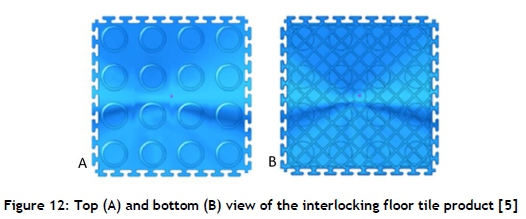
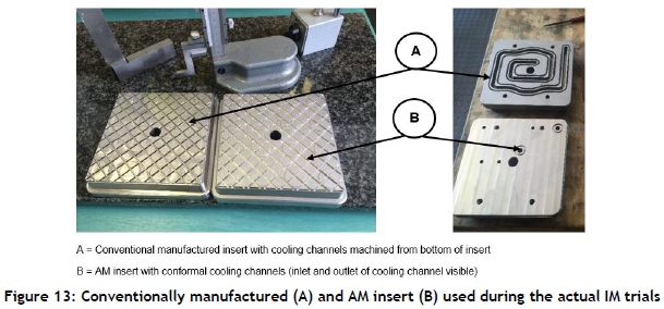
A manufacturing cost and lead-time comparison was also conducted for an AM and a conventionally manufactured insert for an interlocking floor tile product, shown in Figure 12, with outer dimensions of 150 mm x 150 mm x 4 mm.
The conventionally manufactured insert for the floor tile product was designed with cooling channels, considering mould constraints and manufacturing limitations, such as straight line drilling, screw and ejector pin holes. An AM insert for the floor tile product was manufactured through the DMLS process from maraging steel MS1, as shown in Figure 13.
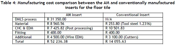
Table 4 shows the cost comparison between the AM and the conventionally manufactured inserts for the interlocking floor tile.
The total manufacturing time for the conventionally manufactured insert, from design to the completed insert, ready for production, was five days. This included CNC programming, CNC machine setup, CNC machining, and fitting the insert into the IM. The total manufacturing time for the AM insert was eight days, which included machine setup, DMLS time, post-processing time (EDM and CNC machining), and fitting into the IM. Although the manufacturing time of the AM insert took longer than the conventional insert, the AM process could occur concurrently with the conventional mould manufacturing processes. During this case study a considerable amount of CNC machining (post-processing) was required on the DMLS insert to obtain the required geometry and surface finish, increasing the manufacturing time of the AM insert.
3.2.3 Production costs of floor tile inserts and break-even analysis
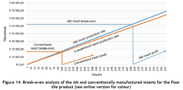
Figure 14 shows the production rates and break-even points for the AM and the conventionally manufactured inserts of the floor tile product. The conventionally manufactured insert's cost of R14 055.63 could be recovered after 88 hours of production - after which it could start to generate a profit - compared with 303 hours required for the AM insert to recover the manufacturing cost of R52 236.38. The AM insert could generate a profit at a faster rate than the conventional manufactured insert due to the reduction in cycle time - but it also had a larger non-recurring cost than the conventionally manufactured insert.
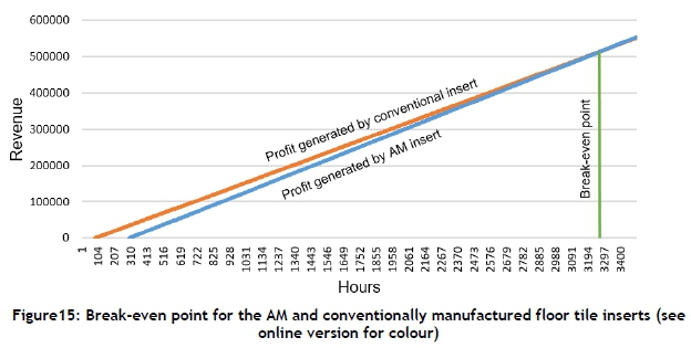
After 103 hours of production, the conventional manufactured insert had already generated a profit after its manufacturing costs had been recovered. The AM insert only recovered its manufacturing cost 303 hours into production. After 3 287 hours of production (400 970 products), the AM insert became more profitable than the conventionally manufactured insert, as shown in Figure 15 below.
For the interlocking floor tile, it would be worth investing in an AM insert with a higher non-recurring cost, if the demand for the product is more than 473 328 products (9 466 m2 of floor tiling).
4 CONCLUSION
From the simulated results in Table 2, it was evident that the AM insert was able to remove heat more effectively than the conventionally manufactured insert. This resulted in a reduced mould temperature of about 30°C in the AM insert during the 20th IM cycle compared with the conventionally manufactured insert after 20 IM cycles. More turbulence was induced inside the conformal cooling channel than inside the conventional cooling channel, resulting in a higher water outlet temperature, as shown in Table 2. These factors resulted in a three-second shorter cycle time for the AM insert. From these results, the benefits of using an AM insert to manufacture the product were clearly shown.
Tables 3 and 4 showed that an AM insert's manufacturing cost is about two to three times more than an insert manufactured using conventional manufacturing techniques. These higher costs could be due to its size and the time required to manufacture the AM insert. An important factor that can also influence the cost of DMLS AM inserts is the Euro to Rand exchange rate and importation costs, as well as post-processing operations such as wire EDM required to remove the insert from the build platform. Although the AM insert's manufacturing costs are higher than the conventionally manufactured insert, it can produce products at a faster rate and generate a profit faster after the break-even point has been reached, as shown in Figure 10 and Figure 14. For the interlocking tile product, using an AM insert with conformal cooling channels would be more profitable if more than 473 328 products (3 287 production hours) were required, as shown in Figure 15. A similar comparison was done for the case study product, and it was found that 47 945 products (586 production hours) were required before the AM inserts with conformal cooling channels would be more profitable, as shown in Figure 11.
From these results it can be concluded that, for certain products, AM inserts with conformal cooling channels will only be beneficial to, or have an influence on, the profitability of a product to be manufactured in high-volume production runs, which are required to recover the higher manufacturing costs of an AM insert. The selection criteria to determine when to use AM inserts for IM applications should be well-defined, where important factors such as part geometry, complexity, and the life cycle of the product to be produced should be considered when making a decision about mould manufacturing techniques. To assist the designer, CAE and CFD simulation software can be used to evaluate and compare different insert and cooling channel designs during the IM process, to gain insight into how the inserts would perform during the IM process.
5 ACKNOWLEDGEMENTS
Financial support from the National Research Foundation (NRF) and the Collaborative Programme in Additive Manufacturing (Contract Ns CSIR-NLC-CPAM-15-MOA-CUT-01) is gratefully acknowledged. Thanks also to the Centre of Rapid Prototyping and Manufacturing (CRPM) for technical and financial support, as well as Mr M. Zwemstra from Ametex for his assistance during the ANSYS® and SIGMaSOFT® simulations.
REFERENCES
[1] Malloy, R.A. 2010. Plastic part design for injection molding. Hanser Gardner Publications, Cincinnati. [ Links ]
[2] Combrinck, J., van der Walt, J.G., Booysen, G.J. & de Beer, D.J. 2018. Evaluating the suitability of Alumide® tooling for injection moulding of different polymers. South African Journal of Industrial Engineering, 29(3), pp. 271-283. [ Links ]
[3] Jahan, S.A. & El-Mounayri, H. 2016. Optimal conformal cooling channels in 3D printed dies for plastic injection molding. Procedia Manufacturing, 5, pp. 888-900. [ Links ]
[4] Wu, T., Jahan, S.A., Zhang, Y., Zhang, J., Elmounayri, H. & Tovar, A. 2017. Design optimization of plastic injection tooling for additive manufacturing. Procedia Manufacturing, 10, pp. 923-934. [ Links ]
[5] Van As, B., Combrinck, J., Booysen, G.J. & de Beer, D.J. 2017. Direct metal laser sintering, using conformal cooling, for high volume production tooling. South African Journal of Industrial Engineering, 28(4), pp. 170-182. [ Links ]
[6] Fu, J. & Ma, Y. 2019. A method to predict early-ejected plastic part air-cooling behavior towards quality mold design and less molding cycle time. Robotics and Computer Integrated Manufacturing, 56, pp. 66-74. [ Links ]
[7] Masakazu, S., Ring, J., Young, C., Oda, Y. & Mori, M. 2017. Manufacturing technology innovative grid molding and cooling using an additive and subtractive hybrid CNC machine tool. CIRP Annals - Manufacturing Technology, 66(1), pp. 401 -404. [ Links ]
[8] Moayyedian, M., Abhary, K. & Marian, R. 2018. Optimization of injection molding process based on fuzzy quality evaluation and Taguchi experimental design. CIRP Journal of Manufacturing Science and Technology, 21, pp. 150-160. [ Links ]
[9] Gurjeet Singh, G., Pradhan, M.K. & Verma, A. 2018. Multi response optimization of injection moulding process parameters to reduce cycle time and warpage. Materials Today: Proceedings, 5, pp. 8398-8405. [ Links ]
[10] EOSINT. Maraging steel MS1: High-performance steel for tooling and mechanical engineering. EOS. Available from: https://www.eos.info/material-m [Accessed on: 01 July 2019]. [ Links ]
[11] Wu, T., Jahan, S.A., Kumaar, P., Tovar, A., El-Mounayri, H., Zhang, Y., Zhang, J., Acheson, D., Brand, K. & Nalim, R. 2015. A framework for optimizing the design of injection molds with conformal cooling for additive manufacturing. Procedia Manufacturing, 1, pp. 404-415. [ Links ]
[12] EOS. Maraging steel MS1 200W. EOS. Available from: https://www.eos.info/material-m [Accessed on: 01 July 2019]. [ Links ]
* Corresponding author: jcombrinck@cut.ac.za

