


Services on Demand
Article
 English (pdf)
 Article in xml format
 Article references
Indicators

Related links
-
 Cited by Google
 -
 Similars in Google
Share

 Permalink
South African Journal of Industrial Engineering
On-line version ISSN 2224-7890
Print version ISSN 1012-277X
S. Afr. J. Ind. Eng. vol.30 n.3 Pretoria Nov. 2019
http://dx.doi.org/10.7166/30-3-2264
SPECIAL EDITION
Development of a Method of Additive Manufacturing by Material Extrusion Along Three-dimensional Curves
D.M. KirkmanI, *; A.F. van der MerweI; R.I. CampbellII
IDepartment of Industrial Engineering, Stellenbosch University, South Africa
IILoughborough Design School, Loughborough University, United Kingdom
ABSTRACT
A method of additive manufacturing (AM) for the extrusion of material along three-dimensional curves is proposed as an alternative to conventional methods of layer-based AM for the manufacture of components designed using topology optimisation. The objectives of the study are to formulate a toolpath-generation algorithm for the extrusion process, to design the testing apparatus and methods for the validation of the proposed extrusion process, and to generate feedback based on the results obtained during testing and validation for possible implementation in topology optimisation software. The outcome of the study is a process by which toolpaths can be generated for simple geometries, and implemented using a mounted extruder serving on to a serial robot-mounted build platform.
OPSOMMING
Die ekstrusie van materiaal langs driedimensionele krommes deur middel van toevoegingsvervaardiging word voorgehou as 'n alternatief vir konvensionele, topologie-optimeerde, laag-gebaseerde toevoegingsvervaardiging. Die doelstellings van hierdie navorsing is om 'n gereedskapstuk trajek algoritme vir die ekstrusie proses te formuleer, om die toetsapparaat en validasie-metodes vir die voorgestelde proses te ontwerp en om terugvoer te gee aan die hand van die resultate. Die einddoel is om die benadering in te sluit in topologie-optimering sagteware. Die resultaat van hierdie studie is n proses waarvolgens gereedskapstuk trajekte genereer kan word vir eenvoudige geometrieë en geïmplementeer kan word deur die gebruik van 'n matrys op 'n serie, robot-gemonteerde bouplatform.
1 INTRODUCTION
The emergence of structural topology optimisation as a design method in which stress analysis is used as a basis for the generation of optimal geometries has created a need for manufacturing processes by which complex geometries can be manufactured with minimum design constraints, and in which there is a clear link between material allocation based on stress distributions to the resulting mechanical properties of the manufactured component [1], [2]. The deposition of material by extrusion directly along three-dimensional load paths in order to optimise mechanical properties is thus an avenue of research that has potential application as a method of manufacturing reliable, load-bearing components with optimised geometries [3].
The aim of the study is to develop and test a method of additive manufacturing (AM) by which material is extruded along three-dimensional curves, for potential application in the manufacture of parts designed using topology optimisation methods. The study has three objectives. The first is the development of a toolpath-generation algorithm for facilitating a method of AM by the extrusion of material along three-dimensional curves. The second is the design and configuration of hardware and test-pieces for the production of simple geometric shapes to benchmark the process with conventional material extrusion 3D printing processes. Finally, based on the limitations in the machine and extrusion parameters observed during toolpath generation and testing, feedback for topology optimisation algorithms is to be formulated.
This study forms part of the 'directional composites through manufacturing innovation' (DiCoMI) project, the main aim of which is to combine various methods of manufacture in the development of a hybrid method by which composite material components can be manufactured with optimised fibre directionality, based on applied loads [4].
2 BACKGROUND
An overview of topology optimisation and the existing methods and limitations of additive manufacturing was performed to assess technology readiness levels for the extrusion of material along 3D curves.
2.1 Topology optimisation and AM
Advancements in (additive) manufacturing methods have enabled the physical realisation of the complex geometries that may result from the application of topology optimisation algorithms [5]. For structural optimisation, the objective function to be minimised is commonly compliance (resulting in a maximisation of structural stiffness), with a specified mass target [6]. Topology optimisations result in the allocation of material to regions of a design space that exhibit the greatest stiffness (or are subject to the highest stresses) under given loading conditions. Stiffness or stress contours correspond to load paths, and hence topology optimisation can be said to allocate material along load paths [7], which can consist of a combination of tensile, compressive, and shear stresses [8].
2.2 Limitations of '2.5D' printing
Fused deposition modelling (FDM) is a method of AM that can be used for the manufacture of components that are designed using topology optimisation, with the addition of fibre reinforcement as a possible method of improving mechanical properties. Conventional FDM printing can be described as a '2.5D' process, since the final structure consists of planar lamina deposited successively in a two-dimensional process. The low inter-layer strength relative to the intra-layer strength of FDM components is well established. A study by Perez, Roberson, and Wicker [9] indicates that tensile strength in the build direction of FDM components printed using ABS could be as low as 50 per cent of the strength when loaded parallel to the layer orientation. An observation made by Zeltmann et al. [10] is that ABS samples loaded perpendicular to the layer orientation failed because of brittle fracture, with no plastic deformation being observed before failure. This is in contrast to significant plastic deformation for samples loaded parallel to the layer orientation [10].
A study by Alaimo, Marconi, Costato, and Auricchio [11] investigated the effect of raster orientation on the intra-layer strength and stiffness properties of ABS samples printed using an FDM 3D printer. Test samples were designed according to the ASTM D3039 standard, and were printed using 100 per cent infill so that the effect of raster angle on tensile strength could be assessed [11]. Samples with a raster orientation perpendicular to the load direction exhibited a tensile strength that was as much as 40 per cent lower than the samples loaded along the raster direction [11]. A similar study by Ziemian, Sharma, and Ziemian [12] observed that the ultimate tensile strength (UTS) obtained for samples loaded along the raster direction reached 94.8 per cent of the UTS for identical injection moulded ABS test specimens, while the strength of samples loaded perpendicular to raster orientation (with no loading across layers) was reported to be 53.7 per cent of the strength of the injection moulded samples [12].
The results of the studies mentioned above indicate highly anisotropic properties for FDM components, even when loaded parallel to layer planes. These studies did not consider the effect of infill type and density on mechanical strength, since 100 per cent infill was used, which is seldom the case in practice [13]. The numerous manufacturing parameters involved in FDM printing, and the effect of these parameters on mechanical properties, thus make the strength and reliability of FDM 3D printed parts difficult to predict.
Fibre reinforcement can be incorporated in the FDM 3D printing process in order to improve mechanical properties. Fibres can either be discrete or continuous, and are laid down along with a polymer base material, generally in planar layers. Error! Reference source not found. below shows the results of a review by Van de Werken et al. [14] showing a tensile strength vs stiffness graph for various materials available for commercial AM. The study reported that the use of continuous fibres led to a significant increase in both tensile strength and modulus for samples loaded in a direction parallel to the plane of fibre deposition, while the use of discontinuous fibres showed a much smaller improvement in strength and stiffness [14]. Van de Werken et al. [14] reported that the mechanical properties of continuous fibre-reinforced FDM composites can be comparable to those of 3D printed metals when normalised by density.

A significant limitation of the use of continuous fibre reinforcement for FDM 3D prints is that fibres cannot be used to address the strength limitations mentioned in the previous paragraphs. Inter-layer strength is not significantly improved as fibres are deposited in layers along with the base material [15]. A study by Yang et al. reported an interlaminar shear strength for 10 weight per cent continuous carbon fibre reinforced ABS samples of 11.7 per cent of the shear strength of identical injection moulded ABS specimens [16]. In addition, Van de Werken et al. [14] state that the interfacial strength for fibre-reinforced thermosets is superior to that of the fibre-reinforced thermoplastics conventionally used for FDM printing. Thus the application of continuous fibre-reinforced FDM composites is limited to simple geometries or load cases where interlaminar shear stresses are kept to a minimum.
2.3 AM process chain
A limitation that can be observed in the conventional method of designing and 3D printing of load-bearing components is the process chain that is conventionally followed. Zeltmann et al. described the AM process chain, as seen in Figure 2 below [10].

CAD software is used to design a component, and a finite element analysis (FEA) may be performed to evaluate the mechanical integrity of the part under the predicted loads. Because the FEA software and slicing software are separate entities, 3D printing process parameters that are implemented using the slicing software (after any FEAs have been performed) may not be taken into account in the stress analysis process. This presents a discontinuity in the design process, since manufacturing parameters are applied after strength predictions are made, implying that stress analyses are unreliable unless the numerous parameters applied in the slicing and toolpath generation phase have been considered upstream in the stress-analysis phase [17]. The gap in the process chain between stress analysis and the assignment of manufacturing parameters is a factor that significantly limits the reliability of (particularly) FDM 3D printing methods for the production of end-use components [18]. A method of AM where toolpaths are generated directly based on stress analysis could, to a large extent, remove this discontinuity.
2.4 Methods of additive manufacture for improvement of properties
Several methods have been developed with the potential to improve the mechanical properties of 3D printed components, and to deposit materials according to stress distributions.
Curved layer fused deposition modelling (CLFDM), also referred to as active-Z printing, is a method of non-planar FDM printing that can be used to improve the mechanical properties of FDM components by the reduction of stair-stepping effects and the orientation of layers according to principal stress trajectories [19], [20]. A paper by Khurana, Simpson, and Frecker presented a method of 3D layer generation for active-Z printing, based on the direction of principal stress trajectories obtained through stress-analysis of a simple beam structure subjected to a point load. Flexural testing of manufactured specimens indicated an increase of 12.3 per cent in flexural strength and 22.8 per cent in flexural modulus for layers oriented according to tensile principal stress trajectories, relative to samples printed using planar layers [21]. Path planning for collision avoidance is an aspect of CLFDM that significantly complicates the process, compared with planar FDM printing [22].
A study by Tam, Mueller, Coleman, and Fine developed a method called stress-line additive manufacturing (SLAM) in which shell structures could be manufactured by adding material along principal stress trajectories [23]. Form finding software was used to generate a shell geometry, where it could be established that there were no out-of-plane shear stresses on the shell when loaded. Based on finite element analyses, 'stress lines' were identified and selected, from which toolpaths were generated. A six-axis serial robot was used for manipulation of a print-head over a contoured surface. Samples printed using this method showed a failure load approaching double that of FDM control samples of equivalent mass [23]. Figure 3 below shows a SLAM sample.

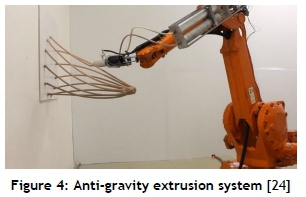
The authors of an article titled 'Anti-gravity 3D printing' developed a method of AM in which material could be extruded along 3D paths without requiring support material. A static mixing nozzle was used, with a two-part acrylic resin supplied by two separate piston-cylinder assemblies that were actuated using a linear screw. The extrusion speed was identified as a critical parameter in determining the success of the process, since a curing rate that is too rapid would result in the nozzle blocking, while a slow curing rate would result in deformation of the extruded strand. In this study, a 'curing point', at which the plastic was considered to be 'set', was made to be 1mm from the nozzle by adjusting the extrusion speed [24]. Heaters were mounted to the extruder nozzle to accelerate the thermoset curing process. A maximum extrusion speed of 20cm/min was obtained.
Extrusion thickness was changed by adjusting the extrusion speed relative to the speed of the robotic arm along its trajectory, so that it was possible to obtain a range of continuously changing diameters of extrusion. This was accomplished without a change in diameter of the extruder nozzle. A potential challenge in robot control was collision avoidance, particularly for extrusion paths in close proximity to each other. However, it was found that the extrusion quality was not significantly affected if the nozzle was not kept tangent to the extrusion path. Hence, 'inclination control' was used to prevent collisions by adjusting the pose of the robot end effector, allowing the nozzle to be oriented at an angle to the segment being extruded. Collisions with the base plate, or with segments that had already been extruded, were thus avoided. The use of inclination control is illustrated in Figure 5 below. No mechanical testing was performed on the extruded components, as the study was architecturally oriented.

An AM method that combines advantages from both FDM and stereolithography (SLA) 3D printing is the method of photopolymer extrusion (PPE). The MASSIVit 3D printer makes use of a UV-curable gel, which is pumped through an extruder using a peristaltic pump. The gel is cured as it exits the nozzle using UV LEDs and, due to the rapid setting of the material, roof geometries can be printed without requiring support material [25]. The use of a photopolymer instead of a thermoplastic improves the intra-layer shear strength, since polymerisation reactions occur between layers as successive layers are added. According to Stansbury and Idacavage, the mechanical properties of SLA 3D printed components are nearly isotropic, due to the chemical bonding (polymerisation reaction) that takes place both within and between the layers [26]. No studies on the mechanical properties of components manufactured using the MASSIVit machine were found; however, due to the material used, the inter-layer bonding process is expected to be similar to that of standard SLA 3D printing.
The methods of AM discussed above illustrate that technology exists for the extrusion of material along three-dimensional paths without requiring support material, and that methods of allocating material based on stress distributions have been established. However, technology incorporating the two approaches above to a combined method of design and (additive) manufacturing apparently does not exist.
3 METHODOLOGY
Based on the observed limitations of '2.5D printing', and the identified means of additive manufacture to improve mechanical properties, a methodology for the development of a method of additive manufacture by the extrusion of material along 3D curves is presented. First, material selection is discussed, followed by an overview of extruder design, the toolpath generation process, and a description of robot and extruder control.
3.1 Material selection
A UV-curable photopolymer gel was selected as a material for testing the extrusion method, for the following reasons:
• The extrusion process can be stopped at any time without the resin hardening in the extrusion nozzle, since no two-part mixer is required. This is a significant advantage over the use of two-part thermosets, which would require continuous extrusion to prevent the resin setting in the nozzle.
• Bonding between adjacent segments does not require significant pressure to facilitate bonding at a join, as would be required for a thermoplastic [27].
• The curing process can be manipulated by adjusting the focal point and intensity of the UV light source being used, thus altering the rate of cure of the photopolymer.
• Photopolymers can have a rapid curing rate, depending on the particular resin and the intensity of UV light used. The MASSIVit 3D printer is capable of nozzle speeds of up to 300mm/s [28].
• As demonstrated by the near-isotropic properties of SLA prints, bonding between extruded segments is expected to be stronger than if a thermoplastic or a two-part thermoset were used, since cross-linking occurs between joined segments even if these segments are not individually cured at the same time [26].
For experimentation purposes, a standard SLA resin was used. This was thickened using fumed silica in a mass ratio of about five per cent in order to produce a thixotropic gel with a sufficiently high viscosity to prevent the gel running before setting. Bubbles introduced during mixing were removed using a vacuum chamber.
3.2 Extruder design
Two options exist for the extruder configuration: an end-effector mounted extruder feeding on to a stationary base, or a fixed extruder feeding on to an end-effector mounted base. In an effort to minimise sagging of the extruded segment after extrusion and before curing, the stationary extruder configuration was selected. The extruder nozzle faces vertically downwards to ensure that no sagging effects occur due to gravity. Figure 6 below shows the extruder configuration.
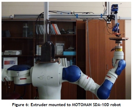
A stepper motor controlled using an Arduino Uno micro-controller with CNC shield is used to power a linear guide system. The photosensitive gel is contained in a syringe, the plunger of which is pushed or retracted using the linear guide system. The syringe is encased in an opaque cylinder to prevent curing due to exposure to sunlight.
UV lights with a narrow (15°) viewing angle are mounted in a circular arrangement around the extruder nozzle. The number and brightness of the LEDs can be changed to adjust the curing rate of the resin. The focal region of the LEDs is adjusted by increasing or decreasing the nozzle tip distance relative to the LED position. An aluminium nozzle with an exit diameter of 3mm was manufactured, so that the nozzle could be fitted to a Luer-lock syringe tip. A 3D printed ring was mounted at the nozzle tip to create a shadow at the nozzle exit, thus preventing the cured resin from adhering to the nozzle.

3.3 Toolpath generation
Toolpaths are generated from simplified 3D CAD geometry by extracting points along 3D curves. MATLAB is then used to calculate the necessary end effector pose for the robot, and to generate a job file for the robot and extruder control. The sections that follow cover the toolpath generation process.
3.3.1 Geometry generation and extraction of points from CAD data
SOLIDWORKS is used to generate CAD geometry. Geometry features are restricted to swept features with a round cross-section of constant diameter. Features can thus be manufactured directly, without requiring simplification.
Points are created along the curves used for swept features, with the linear point density set manually by specifying the number of points along each line segment. A macro is then used for the conversion of these points into an Excel file format. Figure 8 illustrates this process.

3.3.2 Toolpath generation using MATLAB
MATLAB is used to generate toolpaths and to write job files to be read by the robot. By making use of a feature in the INFORM programming language of MOTOMAN that allows for the adjustment of a tool definition within a job, it is possible to generate toolpaths with minimal calculation. The toolpath generation process is presented below:
1. Import the geometry points or 'extrusion points' from an Excel file. The coordinates are relative to the bed mounted on the robot end-effector.
2. Check the order of the points. Reverse the order if necessary to ensure that each extrusion starts at its lowest point relative to the build platform.
3. Consider each point along the curve as a tool centre point (TCP). The position of the TCP relative to the extrusion bed is obtained, using the coordinates of the corresponding extrusion point. Calculate the posture of the 'tool' using a line joining the current extrusion point to the next point. The DX100 controller being used requires that tool posture is specified in the order Rz, Ry, Rx, where the rotation angles specified are the angles about which the end-effector flange coordinates must be rotated sequentially in order to line up with the tool coordinates. Rzis assumed to be zero, and Ryand Rxare calculated using projections of the line mentioned above on to the x-z and y-z planes of the flange coordinate axes respectively.
4. Calculate or calibrate the tool definition of the centre point on the extrusion bed, and use this as a reference tool. Because the end-effector flange and the extrusion bed are in parallel planes, it is not necessary to calculate rotation angles between the reference tool and each extrusion tool. The tool definition for each extrusion point, relative to the end-effector flange, is thus calculated simply by adding the position coordinates of the TCP calculated above to the coordinates of the reference tool. The rotation angles calculated above are used without adjustment.
5. Use an array to store each new tool definition for both its position and its posture.
6. Define extra 'tools' for before and after extrusion takes place, to control the approach and withdrawal of the extrusion bed.
7. Record the coordinate position of the extrusion bed when its centre point is in contact with the extruder nozzle. This point is the point to which each new tool moves during the extrusion process.
8. Use MATLAB to generate a text file to execute the toolpath using the robot. This process converts tool definitions to INFORM commands, and defines the outputs required for the extruder control. For each point in the extrusion process, a new tool is defined by adjusting the definition of the current tool. A linear move command is then used to move the new TCP to the desired pose at the nozzle exit.
By using the method of adjusting tool definition, it is not necessary to calculate the required posture of the end effector, which simplifies the calculations for the 3D toolpaths. In addition, the speed at which each new tool moves to the nozzle reference point is equal to the extrusion speed, leading to simple speed control of the extrusion bed.
3.3.3 Robot and extruder control
A MOTOMAN SDA-10D robot is used for the implementation of toolpaths. Jobs are uploaded as .JBI files using a USB. The extruder controller is programmed so that the UV lights and stepper motor can be controlled using universal 'dry relay' outputs on the robot controller. Five relay outputs are used: three for speed control of the extruder, one for switching of the UV lights, and one for an interrupt signal attached to a hardware interrupt on the Arduino. The Arduino is programmed with set motor speeds, and these are selected based on the state of the relay outputs. The state of the interrupt output determines when the Arduino reads the state of each of the universal outputs of the robot controller. By controlling the stepper motor and UV lights separately, the extruder can be controlled for each different job without re-programming the Arduino between jobs.
4 PROCESS DEVELOPMENT AND PRELIMINARY TESTING
Testing and process development is in progress, with the preliminary and expected results presented below.
4.1 Development of extrusion process
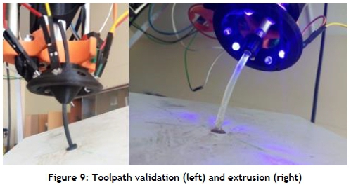
FDM prints of simple curves, mounted on the extrusion bed in the orientation that they would be extruded, were made to validate the calculated toolpaths. The syringe was removed from the extruder, and a dummy nozzle was mounted so that the FDM test part could pass through the nozzle. The extrusion job was then run, and visual examination of the position and tangency of the test part relative to the extruder nozzle confirmed, for multiple parts, that the toolpath being executed by the robot matched the desired extrusion geometry. Once the suitability of the toolpath had been confirmed, the extruder was loaded, and various parameters were adjusted until an extrusion of satisfactory quality was obtained. Figure 9 below shows the toolpath validation process and the extrusion of an arc.
During process development, several parameters were introduced to improve extrusion quality. These are summarised below.
• Priming distance. An extrusion distance was specified for priming to ensure that there is enough gel to stick to the extrusion bed as extrusion begins. This is executed by means of a delay between the extruder motor starting and the start of bed motion.
• 'No-lights' distance. A distance of about 3mm along the extrusion path was set between the beginning of extrusion and the point at which the lights are turned on. This ensures that no resin sticks to the nozzle tip due to the reflection of UV light from the bed when the nozzle and bed are in close proximity.
• An extrusion distance past the end of the extruded part was set to compensate for the distance of about 1.5mm between the nozzle tip and the 'setting point' of the resin.
• A delay between stopping the bed motion and turning the UV lights off was introduced to ensure hardening of the resin at the end of the extrusion.
• Parameters for the horizontal extrusion of segments on the extrusion bed were identified. For this case, the nozzle and bed are kept perpendicular, and a segment is deposited on to the bed, without curing, using the UV LEDs. Once the segment is complete, the bed is lowered slightly and the segment is passed under the nozzle with the LEDs turned on. The segment can thus be cured without causing nozzle blockages as a result of reflection.
• Inclination control was introduced to reduce bed tilt when the tangency of the extrusion with the nozzle would require large angles of bed tilt. A piece-wise equation was generated so that inclination control is only applied to the Ryand Rxangles when the required tilt angles exceed 20°. A maximum tilt angle for Ryand Rxwas set at 40°. Figure 10 below shows the adjustment of inclination angles based on the input angle. A third-order polynomial equation was selected using Excel curve-fitting to describe the desired relationship between input and output angles.

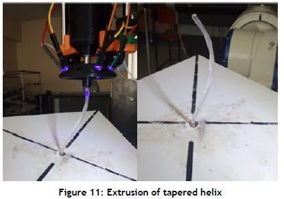
The parameters above are included in the MATLAB code, and implemented using delays and the universal outputs on the robot controller to control the speed and the switching of lights on the extruder. The extrusion of fully 3D curves has been demonstrated, as seen in Figure 11 below, where a tapered helix geometry has been extruded with inclination control to reduce bed tilt.
Further development of the process includes the expansion of the toolpath algorithm to extrude multiple joined segments. The extrusion parameters required for the successful joining of two segments will be investigated, as well as hardware adjustments for the extrusion head to reduce the chance of the UV light bracket and nozzle tip colliding with segments that have already been extruded.
4.2 Proposed testing
Testing will be performed to ascertain both the geometrical accuracy and the surface quality of the extrusions, and to generate a set of guidelines for suitable extrusion speeds, nozzle diameters, and limitations for the maximum curvature that can be obtained while still producing an extrusion of suitable quality. The application of inclination control, as mentioned by Laarman [24], and its effect on extrusion quality, will be further investigated as a way to generate realisable toolpaths for complex geometries.
Mechanical testing will also be performed on the extruded gel, and the results will be compared with those of identical FDM test parts printed with various orientations. Tensile testing on joined extrusions will be performed to assess the mechanical strength between joined segments.
5 EXPECTED RESULTS AND DISCUSSION
Due to the absence of layers in the extrusion process, it is expected that the properties of extruded segments will be significantly less anisotropic than those of FMD 3D printed materials. Based on the strength of the joins between segments relative to the strength of the bulk material, conclusions will be drawn about the suitability of the process for manufacturing load-bearing parts designed using topology optimisation. Due to the use of a photopolymer, the strength of these joins is expected to approach that of the base material. If this is the case, the suitability of the process to manufacture end-use parts lies in the toolpaths that can be obtained. UV-curable resins are typically stiffer and more brittle than the thermoplastics used for FDM 3D printing; thus extruded parts are expected to exhibit brittle failure mechanisms.
It is anticipated that obtaining varying diameters using a single nozzle is feasible, and that the angle at which two segments can be joined is limited by the nozzle thickness, and the possibility of collision with the UV LED mount. The position of the LEDs thus influences the toolpaths that can be obtained, as well as the rate of curing of the photopolymer and the size of the focal region on the extrusion. Increasing the height of the LEDs relative to the nozzle tip reduces the chance of collision, while also reducing the intensity of the UV light and increasing the size of the focal region on the extrusion. The position and intensity of the UV light source is thus critical to determining the range of allowable toolpaths while still allowing for acceptable extrusion speed and quality.
Guidelines for applying the extrusion process to manufacture parts designed using topology optimisation are to be suggested, using the results from the toolpath and mechanical testing. These guidelines include allowable extrusion speeds and diameters, as well as feasible toolpaths - specifically for joining extruded segments.
A significant improvement that could be made to the extrusion process is to implement an offline simulation to assess the feasibility of toolpaths before being implemented on the robot. The use of inclination control, where necessary, to avoid singularity would result in fewer restrictions on toolpaths, and in toolpaths that are known to be achievable before a job commences.
6 CONCLUSION
A method of additive manufacturing by the extrusion of a photopolymer along three-dimensional curves is proposed. Toolpaths are generated for simple swept features, and implemented using linear move commands between the extrusion points on a Motoman SDA-10D serial robot. A stationary extruder, powered using a stepper motor and controlled using an Arduino micro-controller, is used to extrude an SLA resin with fumed silica additive on to a base plate mounted to the robot end-effector. UV LEDs are used as a radiation source to cure the photopolymer. The process has been validated for single, simple extruded segments, with developments of the toolpath algorithm proposed for more complex geometries.
Testing is to be performed to determine the allowable toolpaths of the system, as well as the mechanical properties of the extruded components. It is expected that components will have properties that are more isotropic than those of FDM components, with the range of allowable toolpaths being largely dependent on the extruder geometry and the implementation of inclination control.
The results of the testing will lead to conclusions about the applicability of the proposed method for the manufacture of components designed using topology optimisation, where material is extruded directly along principal load paths. A future avenue of research is the inclusion of chopped or continuous fibres in the extrusions to improve the mechanical properties.
REFERENCES
[1] Guessasma, S., Zhang, W., Zhu, J., Belhabib, S. & Nouri, H. 2015. Challenges of additive manufacturing technologies from an optimisation perspective. Int. J. Simul. Multidiscip. Des. Optim., 6(1), p. A9. [ Links ]
[2] Langelaar, M. 2016. Topology optimization of 3D self-supporting structures for additive manufacturing. Addit. Manuf., 12, pp. 60-70. [ Links ]
[3] Pei, E., Campbell, R.I. & de Beer, D. 2014. Entry-level RP machines: How well can they cope with geometric complexity? Assem. Autom., 31(2), pp. 153-160. [ Links ]
[4] DiCoMI. 2017. Research and innovation staff exchange (RISE) call: H2020-MSCA-RISE-2017, PART B Project Title: Directional Composites through Manufacturing Innovation. [ Links ]
[5] Munk, D.J., Vio, G.A. & Steven, G.P. 2015. Topology and shape optimization methods using evolutionary algorithms: A review. Struct. Multidiscip. Optim., 52(3), pp. 613-631. [ Links ]
[6] Larsson, R. 2016. Methodology for topology and shape optimization: Application to a rear lower control arm. Masters Thesis. Department of Applied Mechanics, Chalmers University of Technology, Gothenburg, Sweden. [ Links ]
[7] Bastien, C., Christensen, J., Blundell, M.V. & Kurakins, J. 2012. Lightweight body in white design using topology-, shape and size optimisation. World Electr. Veh. J., 5(1), pp. 137-148. [ Links ]
[8] Kelly,D.W. 2000. Interpreting load paths and stress trajectories in elasticity. Eng. Comput., 17(2), pp. 117135. [ Links ]
[9] Torrado Perez, A.R., Roberson, D.A. & Wicker, R.B. 2014. Fracture surface analysis of 3D-printed tensile specimens of novel ABS-based materials. J. Fail. Anal. Prev., 14(3), pp. 343-353. [ Links ]
[10] Zeltmann, S.E., Gupta, N., Tsoutsos, N.G., Maniatakos, M., Rajendran, J. & Karri, R. 2016. Manufacturing and security challenges in 3D printing. JOM, 68(7), pp. 1872-1881. [ Links ]
[11] Alaimo, G., Marconi, S., Costato, L. & Auricchio, F. 2017. Influence of meso-structure and chemical composition on FDM 3D-printed parts. Compos. Part B: Eng., 113, pp. 371-380. [ Links ]
[12] Ziemian, C., Sharma, M. & Ziemian, S. 2012. Anisotropic mechanical properties of ABS parts fabricated by fused deposition modelling. In Mechanical Engineering, Turkey: IntechOpen, pp. 159-179. [ Links ]
[13] Fernandez-Vicente, M., Calle, W., Ferrandiz, S. & Conejero, A. 2016. Effect of infill parameters on tensile mechanical behavior in desktop 3D printing. 3D Print. Addit. Manuf., 3(3), pp. 183-192. [ Links ]
[14] Van de Werken, N., Hurley, J., Khanbolouki, P., Sarvestani, A.N., Tamijani, A.Y. & Tehrani, M. 2019. Design considerations and modeling of fiber reinforced 3D printed parts. Compos. Part B: Eng., 160(December 2018), pp. 684-692. [ Links ]
[15] Caminero, M.A., Chacón, J.M., García-Moreno, I. & Reverte, J.M. 2018. Interlaminar bonding performance of 3D printed continuous fibre reinforced thermoplastic composites using fused deposition modelling. Polym. Test., 68(March), pp. 415-423. [ Links ]
[16] Yang, C., Tian, X., Liu, T., Cao, Y. & Li, D. 2017. 3D printing for continuous fiber reinforced thermoplastic composites: Mechanism and performance. Rapid Prototyp. J., 23(1), pp. 209-215. [ Links ]
[17] Liu, J. & To, A.C. 2017. Deposition path planning-integrated structural topology optimization for 3D additive manufacturing subject to self-support constraint. CAD Comput. Aided Des., 91, pp. 27-45. [ Links ]
[18] Kele§, 0., Blevins, C.W. & Bowman, K.J. 2017. Effect of build orientation on the mechanical reliability of 3D printed ABS. Rapid Prototyp. J., 23(2), pp. 320-328. [ Links ]
[19] Chakraborty, D., Aneesh, R.B. & Choudhury, R.A. 2008. Extruder path generation for curved layer fused deposition modelling. CAD Comput. Aided Des., 40(2), pp. 235-243. [ Links ]
[20] Khurana, J.B., Dinda, S. & Simpson, T.W. 2017. Active-Z printing: A new approach to increasing 3D printed part strength. Solid Free. Fabr. Symp, Austin, Texas, pp. 1627-1644. [ Links ]
[21] Khurana, J.B., Simpson, T.W. and Frecker, M. 2018. Structurally intelligent 3D layer generation for active-Z printing. Solid, Free. Fabr. Symp, Austin, Texas, pp. 2413-2426. [ Links ]
[22] Ahlers, D. 3D printing of nonplanar layers for smooth surface generation. [ Links ]
[23] Tam, K.-M.M., Mueller, K.T., Coleman, J.R. & Fine, N.W. 2016. Stress line additive manufacturing (SLAM) for 2.5-D shells. J. Int. Assoc. Shell Spat. Struct., 57(4), pp. 249-259. [ Links ]
[24] Laarman, J., Jokic, S., Novikov, P., Fraguada, L.E. & Markopoulo, A. 2014. Anti-gravity additive manufacturing. In Fabricate 2014: Negotiating design & making, Zurich: UCL Press, pp. 191-197. [ Links ]
[25] Molitch-Hou, M. 2016. Massivit 3D brings large-scale 3D printing to the world of marketing. [Online]. Available: https://www.engineering.com/3DPrinting/3DPrintingArticles/ArticleID/13242/Massivit-3D-Brings-Large-Scale-3D-Printing-to-the-World-of-Marketing.aspx. [Accessed 05-Jul-2019]. [ Links ]
[26] Stansbury, J. & Idacavage, M.J. 2016. 3D printing with polymers: Challenges among expanding options and opportunities. Dental Mat., 32(1), pp.54-64. [ Links ]
[27] Rodríguez-Panes, A., Claver, J. & Camacho, A.M. 2018. The influence of manufacturing parameters on the mechanical behaviour of PLA and ABS pieces manufactured by FDM: A comparative analysis. Materials (Basel), 11(8), pp. 1333-1354. [ Links ]
[28] MASSIVit 3D. 2015. MASSIVit 3D. [Online]. Available: https://massivit3d.com/solutions/3d-printers/. [Accessed: 08-Jul-2019]. [ Links ]
* Corresponding author: 23320214@sun.ac.za

