


Services on Demand
Article
 English (pdf)
 Article in xml format
 Article references
Indicators

Related links
-
 Cited by Google
 -
 Similars in Google
Share

 Permalink
South African Journal of Industrial Engineering
On-line version ISSN 2224-7890
Print version ISSN 1012-277X
S. Afr. J. Ind. Eng. vol.30 n.2 Pretoria Aug. 2019
http://dx.doi.org/10.7166/30-2-2032
GENERAL ARTICLES
An integrated system for process-fixture layout design optimisation for cubical parts
A.A. Khan*; G. Moeenuddin; A.H. Kazim; M.S. Kamran; M. Asim
Mechanical Engineering Department, University of Engineering & Technology Lahore, Pakistan
ABSTRACT
In this article, an integrated computer-assisted process-planning and computer-assisted fixture layout planning system is presented for the automatic generation of process and fixture maps. The part feature model is created using various algorithms and the geometric reasoning approach. The feature-based methodology based on the machining database is then applied for the generation of process maps. The setup scheme algorithm allocates each feature to a definite setup based on its location. The part geometric database and setup plan aids the fixture layout planning process. During fixture layout planning, the standard fixture rules are applied to determine the locating arrangement and feasible datum along with the suitable positions using a fixture database for initial fixture layout planning data. Visual C++ is used to implement the proposed methodology because it interacts with current computer-aided design software. Then a case study is presented to develop an initial fixture layout. Afterwards, the ANSYS parametric design language optimisation tool is applied to automatically optimise locator and clamp positions that yield minimum workpiece deformation. At the end, finite element analysis results depicting deformation magnitudes are presented.
OPSOMMING
'n Geïntegreerde, rekenaargesteunde prosesbeplanning en rekenaargesteunde hegstuk-uitleg beplanningstelsel vir die outomatiese generasie van proses- en hegtingskaarte word voorgehou. Die onderdeel kenmerkmodel is gegenereer met verskeie algoritmes en die geometriese beredeneringsbenadering. Die kenmerk gebaseerde metodologie, wat op die masjineringsdata-basis gebaseer is, is dan toegepas vir die generasies van proseskaarte. Die opstellingskema algoritme ken elke kenmerk toe aan 'n bepaalde opstelling gebaseer op sy ligging. Die onderdeel geometriese databasis en opstellingsplan dra by tot die hegtingsuitleg beplanningsproses. Tydens hegstuk-uitlegbeplanning word die standaard hegstuk reëls toegepas om die ligging en haalbare verwysingspunt te bepaal saam met geskikte posisies deur middel van 'n hegstukdatabasis as vertrekpunt. Visual C++ is gebruik om die voorgestelde metodologie te implementeer omdat dit met bestaande rekenaargesteunde ontwerpspakkette kan koppel. 'n Gevallestudie word dan ter illustrasie voorgehou. Daarna word ANSYS se optimiseringsfunksie toegepas om die optimale klamp-posisies, wat werkstuk deformasie minimeer, te bepaal. Laastens word 'n eindige element analise wat deformasie-groothede aandui voorgehou.
1 INTRODUCTION
A critical aspect in recent manufacturing facilities is to produce a variety of products in short period of time. Subsequently, adaptable manufacturing methods are emerging rapidly to compete with international markets. The process of computer-aided design (CAD) and computer-aided manufacturing (CAM) assisted the achievement of very advanced levels of automation in manufacturing methods that was not conceivable earlier. CAD/CAM packages are devised to merge CAD, Computer Aided Process Planning and CAM in a hardware conformation; this helps the client to perceive, design, anticipate, and govern the product manufacturing with the automation of as many actions as possible [1,2].
A number of factors contribute to organisational capacity, one of them being the use of fixtures to increase the pace of production. A fixture is a mechanism because it eliminates individual registration, placing, and frequent checking before the commencement of the real operation. It's the need for time to devise the systematic methodologies that integrate layout design in an automatic way rather than designing the actual fixture itself [3].
With the advent of CAPP software, the demand for skilled workers and the assurance of consistent production plans is reduced due to the elimination of duplicated work and clashes that arise in intricate designs [3]. Facilitating the design engineer in the conceptual stage needs an efficient feature recognition technique that operates in an interval matter of minutes, and is capable of handling diverse CAD formats. Several feature extraction/recognition methods are developed. Joshi and Chang [4] developed the attribute adjacency graph (AAG) to extract the form features of a workpiece. The node in this graph symbolises the workpiece face, and the arc represents edges in boundary representation (B-rep). Lockett and Guenoy [5] proposed a mid-surface-based feature recognition methodology for molded parts. Emad S. Abouel Nasr [6] proposed an approach for the extraction of manufacturing features using the initial graphics exchange specification (IGES) format of a CAD file, and decoded the data into manufacturing information. Zhou [7] made use of an object-oriented method for the provision of an interface with computer-aided drawings that extracted the part data file automatically into a neutral file. Amaitic and Kilic [8,9] employed the concepts of STEP feature-based modelling and hybrid intelligent techniques such as neural network and fuzzy logic to develop a computerised system to integrate design and process planning. Locating a scheme is determined by fixture planning and the feasible locating and clamping area in each setup plan in the final fixture assembly. Liu and Wang [10] established a hybrid method, including knowledge-built rules and geometry-based approaches, in which the machining priority is decided on the basis of knowledge, and the sequence of features is determined by geometric rationalisation. Tseng [11] described a feature-based model for the development of a modular fixture by producing an intermediate workpiece after a feature is machined. Nee et al. [12] described an expert system based upon rules for designing fixtures automatically in which locating and clamping surfaces and points were recognised by applying rules along with mathematical analysis. Boerma and Kals [13] presented a computer-aided system that can automatically generate fixture set-ups and design prismatic parts. The selection process is based on the topologyof and the geometric associations among different part features. Fuhet al. [14] established a unified system that allows for the inception of manufacturing procedures after the completion of a part design. They used the CADLOG system to comprehend the interface between the graphics system and the planning sections. Babu et al. [15] established software for planning the fixture layout automatically from 2-D drawing data. The methodology emphasised the determination of the most feasible locating and clamping positions in agreement with the 3-2-1 locating scheme, while taking into consideration the geometrical and dimensional limitations. Auto LISP was used to develop the system.
The reviewed literature shows that both process planning and fixture layout planning tasks are handled either as separate problems or within a CAD environment. Therefore, there is a need to link the CAPP and CAFLP functions in an independent environment. This paper proposes an independent object-oriented methodology for the generation of process and fixture maps.
2 MATERIALS &METHOD
The proposed methodology generates the CAPP and CAFLP using an object-oriented approach. The generative CAPP method is applied because of its ability to provide detailed information on the acquired process strategies for the selected manufacturing parts. The proposed methodology is based on the modularity concept that is incorporated in the fixture planning phase to avoid the need for dedicated fixtures. The developed application automatically generates the CAPP and CAFLP for 3-D prismatic (milling) parts. The STEP AP-203 file is used as an input to the system. The CAPP program uses a CATIA V5-generated 3-D solid model. The file having geometric data was created by the extraction of the pertinent data from a STEP file using the developed object-oriented technique. The developed algorithms were used to recognise and assemble form feature faces and to establish their geometrical properties. The technical features contained in the part were extracted and recognised by using developed logical rules based upon geometric reasoning. The machining database contains the machine operation, cutting tool, machine, and tool access direction, created on the basis of extracted feature data. The setup strategy algorithm allocates all recognised feature(s) to a specific setup based on feature location. A rule base is established, based on process plan data, to determine the suitable locating arrangement and feasible positions for locators and clamps for the modular fixture assembly. The fixture rules are then expressed to determine the suitable positions of location and clamping, based on the part's geometric constraints and the modular fixture database.
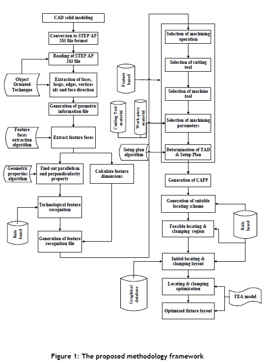
In the optimisation phase of locator and clamp positioning, the geometry of the workpiece is imported into ANSYS APDL and the meshing of workpiece geometry is performed. Afterwards, the boundary conditions - i.e., the initial layout of the locators and clamps are applied and the model is placed under clamping forces. The forces model is then solved, and subsequently the looping is performed against the limits prescribed for the design variables in order to obtain the optimised fixture layout at which the workpiece exhibits minimum deflection. The developed methodology is illustrated in Figure 1.
2.1 Computer-aided process planning
Fixture and setup planning are vital in the CAPP system. Both kinds of planning are performed by (1) combining features or operations into setups; (2) finding appropriate locating surfaces for all setups; (3) ordering the setups; and (4) ordering the processes in every setup [16].
The CAPP system presented in this methodology extracts the geometric data from STEP, performs feature recognition, plans the setup, and generates the process plans. The CAFP system uses CAPP data to find feasible locating and clamping regions, based on the modular fixture assembly.
2.1.1 Geometric data extraction from STEP AP 203
STEP AP 203 is a customary format to convert CAD files to an object-oriented data structure. By using the standard format of STEP AP 203, a number of CAD systems such as Pro-E, Uni-Graphics (UG), CATIA, and Solid Works can be used. Geometrical and topological information in the STEP file data is embodied in the form of individual units. These STEP entities (Closed_Shell, Advanced_Face, Face_Outer_Bound, Edge_Loop, Axis2placement 3D, etc.) are mapped in C++ classes to extract the geometrical and topological data from STEP AP 203. The next step is to generate an output data extraction file by redefining these STEP entities into a new object-oriented data structure. Each face, edge, and vertex has been assigned its own distinct identification to aid the feature recognition process. Moreover, external loops, internal loop, and line, circular, and conical edges are identified, as shown in Figure 2.

2.1.2 Feature recognition
The next step is to locate and recognise the manufacturing features in the geometrical file of the workpiece. For this purpose, algorithms are developed for the identification, extraction, and grouping of feature faces along with their dimensions contained in the part. Moreover, the geometric properties such as parallelism, perpendicularity, concavity, and convexity are established. The logical rules are then created to recognise these technical features, along with their dimensions.
2.1.2.1 Feature faces extraction and dimensional algorithm
The generated output file contains the geometric information of the part (Figure 2). The next step is to identify and extract feature faces and their dimensions. The extraction process is defined below:
1. Read all faces of part geometrical file.
2. Extract x,y,z values for all edges/vertices.
3. Generate min X < all x values, max X > all x values, min Y< all y values, max Y> all y values, min Z< all z values, max Z> all z values.
4. Extract x,y,z values of all edge loops of the faces.
5. Filter the faces that have the same coordinate (x,y,z) values all through the edge loop, such that this value is equal to either the min or the max X,Y,Z value of the workpiece (boundary faces in grey colour, as shown in Figure 3).

6. Filter the faces that have the same coordinate (x,y,z) values all through the edge loop, such that this value is greater than the min and less the than max X,Y,Z value of the workpiece (plane or semi-circular feature faces in white colour).
7. Filter the faces that have no constant coordinate (x,y,z) values all through the edge loop, but either one or two coordinate values are greater than the min and less than the max X,Y,Z value of the workpiece (inclined or quarter cylindrical feature faces).
8. Extract all the faces found in steps 6 and 7.
9. Check connectivity between the faces by edge number.
10. Group all faces as one unit on the basis of their connectivity.
11. Establish the feature unit location as XY, YZ, or ZX.
12. Dimensions are calculated from the start and end of vertices by using a distance formula.
12.1. The length, width, and height are marked according to unit location.
12.2. The radius value is extracted directly from each circular edge of the geometric extraction file.
After extracting the feature faces and their dimensions, the next step is to establish their geometric properties, such as parallelism and perpendicularity, concavity and convexity, etc. These properties will be established by applying the following steps:
2.1.2.2 Parallelism and perpendicularity
[1] Extract the vector direction of each face in the data extraction file.
[2] Find the angle between two faces by using the dot product formula.
[3] If the angle between the two faces is either 0 or 180 degrees, the faces are parallel.
[4] If the angle between the two faces is either 90 or 270 degrees, the faces are perpendicular.
2.1.2.3 Concavity/convexity
[1] Extract the vector direction of each edge in the data extraction file.
[2] Calculate the angle between two edges by using the dot product formula.
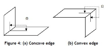
[3] If the angle between the two edges is < 180degrees, the edges are concave (Figure 4a).
[4] If the angle between the two edges is> 180 degrees, the edges are convex (Figure 4b).
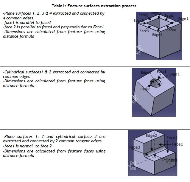
The required feature faces are now extracted and assembled by applying the above-mentioned algorithms. Moreover, parallelism/perpendicularity between the faces and concavity/convexity between the edges are established. The output data obtained from these algorithms are listed in Table 1.
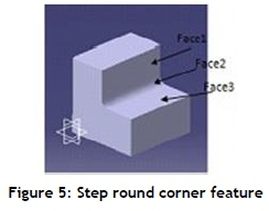
2.1.2.4 Recognition algorithm (production rules)
The logical rules are now constructed, based on the feature extraction procedure, to identify all of the manufacturing features contained in the developed feature library (Figure 5). Every feature has been assigned an exclusive ID. The sample rule is described here:
2.1.3 Process and setup plan generation
A machining database is developed to assign manufacturing process, machine tool, and process parameters for all types of extracted features. Afterwards, the following algorithm is established to generate the automated setup plan.
1. Define the workpiece coordinate system and possible tool access direction (TAD) for a cubical workpiece machined on a milling centre, as shown in Figure 6.

TAD-1 Vector Point = (1, 0, 0) represents +X direction
TAD-2 Vector Point = (-1, 0, 0) represents -X direction
TAD-3 Vector Point = (0, 1, 0) represents +Y direction
TAD-4 Vector Point = (0, -1, 0) represents -Y direction
TAD-5 Vector Point = (0, 0, 1) represents +Z direction
TAD-6 Vector Point = (0, 0, -1) represents -Z direction
2. Allocate a specific tool access direction to each feature in order to assign it to a definite setup.
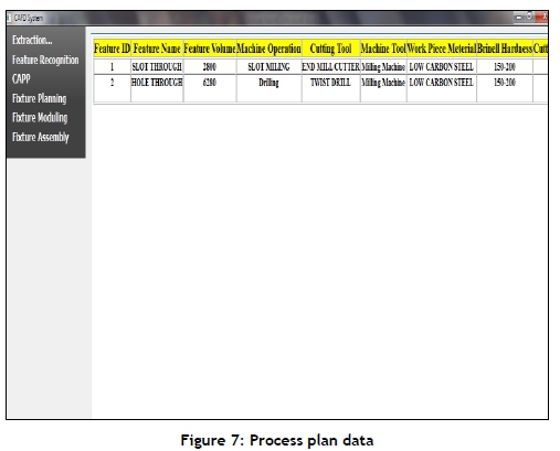
The fraction of a sample CAPP file for the part containing two simple features is presented as a screenshot in Figure 7.
2.2 Computer-aided fixture layout planning (CAFLP)
CAFLP includes the fixture planning and layout planning phases. Fixture planning helps to determine the locating arrangement and candidate faces for locating and clamping, based on the CAPP data. The aim of fixture planning is to constrain all the part's degrees of freedom and to select feasible locating and clamping faces. The computer-aided fixture layout planning activity is triggered after fixture planning to figure out the appropriate locating and clamping regions/points for the modular fixture layout generation, built on the fixture database.
2.2.1 Locating scheme
In setup planning, it is essential to constrain some degrees of freedom so that the technical feature surfaces can be located and oriented in accordance with the TAD. For cubical-shaped workpieces, usually 3-2-1, base 2-1 and 4-2-1 locating schemes are used to restrict the required degrees of freedom.
2.2.2 Locating and clamping surfaces
The prospective locating surfaces must be directed along three mutually perpendicular surfaces. Clamps should be placed in such a way that the clamping force is directed and supports the workpiece. Top and side clamps are two usual clamping types. The top clamp exerts a force that is normal to the base plate, while the side clamp exerts a force in parallel to the fixture plate. As top clamping is given preference over side clamps, a fixture layout with a top clamping arrangement will be given preference [17] (Figure 8).

The datum plane is the primary locating plane of the part. It depends on the part's positioning against the machine tool. For the selection of the edge-locating surface, the suitable edge-locating side with a bigger area are taken as the secondary locating surface, and two locators are positioned there; and the smaller available side is the tertiary locating surface, and one locator is placed on it (3-2-1 rule). Four input parameters are considered for the selection of the possible locating and clamping datum. These are the primary datum surface, the boundary surfaces, the orientation with respect to the primary locating surface, and the face surface area.
2.2.3 Modular fixture database
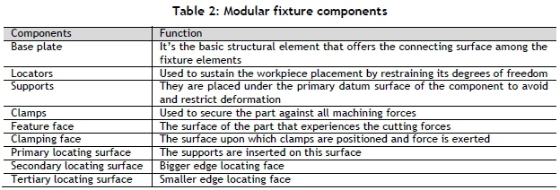
Generally, the fixture can be constructed from many elements such as supporting pins, locators, and clamping devices. The modular fixture elements and their associated part surface are briefly represented in Table 2.
The fixture element structured database will consist of the modular elements for the fixtures. A fixture element can be classified into either a single basic element or a composite element. Any element can perform only one task, such as supporting, locating, or clamping.
2.2.4 Initial edge locating area
The edge locating points are on the suitable area of the secondary and tertiary faces of the part. The suitable area/region is defined in Figure 9 as:

Feasible edge locating area = Total area of locating face-feature area
The locating points are placed within this area on the extreme ends to offer better locating accuracy. The arrow indicates the search direction for feasible edge locating points. The height of the locators should be around the centre of the locating face for maximum stability during machining operation.
2.2.5 Initial supporting area
The supports should be placed on the primary datum surface of the workpiece, as shown in Figure 10. The following points should be considered while placing the supporting elements.
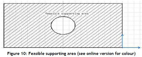
1. The supports must make contact with the part and the base plate to provide rigid support.
2. Supports should be positioned as far as possible to guarantee workpiece stability against the cutting forces. For the 3-2-1 locating scheme, the triangle formed by the supporting points with the largest area is selected.
3. The centre of mass of the workpiece should be within the region that is formed by the base locating /supporting elements.
2.2.6 Initial clamping region
The customary restraints that must be achieved before the actual arrangement of the supports and clamps are given below for a top clamping arrangement.
The physical requisites to be fulfilled to certify that the positions of the supports and clamps are the most appropriate are given below:
1. The clamps should be positioned as far apart as possible to guarantee workpiece stability.
2. The feasible top clamping region must be inside the closed region made by the supporting components to nullify the overturn of the workpiece, as shown in Figure 11 (hatched area).

3. To minimise workpiece deformation, the clamps are applied on the non-machined surface of the workpiece.
The clamps should be placed in such a way that the clamping force is directed on to the tough reinforced portion of the workpiece. The clamping force should always be directed towards the locators so that it forces the workpiece to be in contact with all locators. The selection rules prioritise the use of top clamps over side clamps, and the appropriate element size can be determined for all the clamping positions.
The accessible clamping positions are found so that machining crash is avoided by inspecting all clamping holes around the workpiece. The fixture layout points that are not within the top clamping area are left out. The scheme is laid out in the steps given below:
1. Obtain contender clamping points individually for all sides of the workpiece.
2. Determine the external edge loop(s) of face(s) for the clamping surface.
3. Obtain all the edges of the selected clamping surface(s) to define the feasible top clamping array.
4. Compare each contender clamping coordinate value with the feasible top clamping array.
5. Eliminate each location from the record of contender clamping points that is outside the clamping array.
7. Extract all face_bounds (internal features) of the top clamping face(s).
8. Define the face_bound(s) range from the extracted edge curve points.
9. Compare each face_bound range with the clamping points that lie inside this range.
10. Eliminate clamping points that are inside the face_bound range from the candidate list.
11. Feasible clamping points are also compared with the selected triangle made by the supporting components.
12. Feasible top clamping points should be within the triangular area made by the supporting components.
The appropriate locating and clamping points are thus determined using these fixture rules.
3 IMPLEMENTATION AND LAYOUT OPTIMISATION
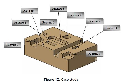
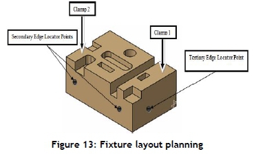
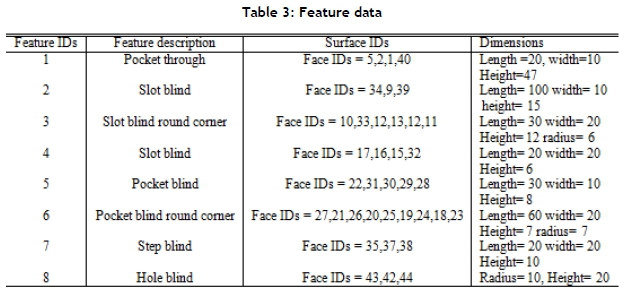
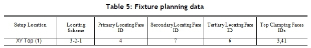
The suggested approach is tested and endorsed using a case study. CATIA V5 is used to create the solid model, as presented in Figure 12. The part contains eight manufacturing features. The geometric information file extracted 44 faces. Fourteen feature faces are recognised and grouped, as shown in Table 3. The process parameters are defined for every feature, along with the setup plan, as represented in Table 4.The output of fixture planning represents the locating arrangement and locating/clamping faces shown in Table 5. Therefore, the allowable limits of the locating and clamping regions are defined by the edges of these faces. The fixture layout planning rule base then determines the appropriate locator and clamp fixing points, as illustrated in Figure 13 and listed in Table 6. The two secondary edge locators are placed adjacent to the secondary locating face on the two holes of the base plate that are furthest apart. The third edge locator is positioned at the hole near the middle of the tertiary locating face. Three supports and two clamps are positioned at furthest apart holes ensure that the clamping arm is inside the supporting triangle area and outside the feature area (Figure 11).

3.1 Automatic fixture layout optimisation
The boundary conditions - i.e., the support and clamp locations - of the selected workpiece need to be optimised to minimise workpiece deformation and maximise locating accuracy. The primary aim of optimisation is to maximise machining accuracy and minimise workpiece deformation. The locator actually fulfils two practical purposes: (1) it locates and stabilises the workpiece, and (2) it helps to minimise part displacements. The optimisation study tries to fulfil both requirements, using only one design parameter: the locator positioning on the surface of the workpiece.
There are three optimisation variables with which we deal in this process: design variables (DVs), state variables (SVs), and the objective function. The operator should fully understand these parameters.
The optimisation is performed in ANSYS using the sub-problem approximation method. A STEP file of the part is imported into ANSYS for that purpose. The ANSYS analysis file consists of the whole analysis sequence - i.e., preprocessing, solution, and post-processing that is to be followed during looping. It contains a parametrically defined model that represents all inputs and outputs as parameters and the objective function. The loop file exists in the operational directory, and is used by the control file to form the model. The control file prepares the design variables; describes the viable design space, optimisation method, and looping controls; and performs the optimisation.
A loop is one pass through the analysis cycle. The output from the final performed loop is saved. The optimisation might consist of one or more loops; these loops provide new design outcomes. The optimisation database contains the optimisation variable definitions, the parameters, all of the optimisation conditions, and the collected design sets.
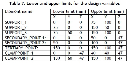
The optimum design is attained by varying the DVs that are autonomous quantities. Upper and lower limits are defined for the design variables, which act as restraints. In our case, the design variables are the positions of the locator and clamp; their limits are provided in Table 7. The SVs are dependent measures that control the design. A state variable can have both a single and a double-sided limit. In our case, the state variable is the Von Mises stress, and its value should be less than the yield strength of our workpiece material. The objective function is the dependent variable that we are trying to minimise. It must be a function of the DVs - i.e., a change in the value of the DVs should also bring about a change in the objective function. In our case, the objective function is the maximum displacement of the part.
A design set is an exclusive set of parameter values that symbolise a specific model configuration. Usually, a design set is categorised by the optimisation variable values; however, it includes all the parameters that are not identified as optimisation variables as well. A viable design is one that fulfils all the specified constraints on the SVs and DVs.
As we have to attain minimum workpiece deformation against an optimised fixture layout, we assume the clamping forces to be 5000N for both top clamps. The deformation of the preloaded model increases only slightly when it is fully loaded, which indicates that the clamping forces are major contributors to deformation [22]; so we only considered them in this study. The material properties for the workpiece and fixturing elements are given in Table 8.

Table 9 lists all of the optimisation variables involved in this research.

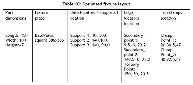
After the completion of the optimisation analysis, the results are retrieved and used to find out the corresponding deformation for both fixture layouts using finite element analysis. The optimised positions of the locators and clamps are given in Table 10.
The maximum displacement in the preloaded workpiece model in the initial and optimised fixture layouts is shown in Figure 14 (a & b). The displacement was 0.0577mm in the initial configuration, and was reduced to 0.0368mm after optimisation.

4 CONCLUSION
The article has presented an integrated methodology for CAPP-CAFLP, based on an object-oriented technique. The suggested methodology was carried out using C++ together with current CAD software. The suggested approach was successfully applied to the selected cubical part. The relevant geometrical information contained in the STEP AP 203 file was extracted in the form of faces, edges, and vertices data, along with their IDs. The advantage of geometric data extraction is that it determines the feasible region during fixture planning. The integrated recognition algorithms and the rule-based systems were applied to identify and recognise the technical features contained in the CAD part. The feature database was used to determine the process and setup plans. Sensible rules were set up to establish the locating arrangement and possible locating and clamping surfaces during fixture planning. The feasible region limits the selection and assembly of modular fixture components. Various algorithms were developed and applied, based on the fixture rules, the modular fixture database, and the part geometrical constraint to establish the suitable locating and clamping points for the final fixture layout planning.
The initial fixture configuration was developed using some generic fixture design knowledge and rules, while considering the constraints of base plate hole spacing. Afterwards, an automatic approach was adapted to optimise the locating and clamping locations in order to obtain minimum workpiece deformation. This approach is based on the sub-problem approximation method offered by the ANSYS package. This technique can achieve both the minimisation of the maximum displacement and an assessment of workpiece stability. In the event of workpiece instability, the ANSYS will indicate a rigid body motion and will not provide a solution.
REFERENCES
[1] Javorick, L., Cabadaj, J. & Chvojka, D. 1990. Aspects of computer-aided fixture design. CIMS, 3(2), pp. 111-114. [ Links ]
[2] Kurian, K.T., Gary, W. & Fischer, U. 1996. Integrating CAD/CAM software for process planning applications. Journal of Materials Processing Technology, 61, pp. 87-92. [ Links ]
[3] Nee, A.Y.C., Tao, Z.J. & Senthil Kumar, A. 2004. An advanced treatise on fixture design and planning. London: World Scientific Publishing Co. [ Links ]
[4] Joshi, S. & Chang, T.C. 1988. Graph based heuristics for recognition of machined features from 3D solid model. Computer-Aided Design, 20, pp. 58-66. [ Links ]
[5] Lockett, H.L. & Guenov, M.D. 2005. Graph-based feature recognition for injection moulding based on amid-surface approach. J. Computer-aided Design, 37(2), pp. 251-262. [ Links ]
[6] Abouel Nasr, E.S. 2006. A new methodology for extracting manufacturing features from CAD system. Computers & Industrial Engineering, 51, pp. 389-415. [ Links ]
[7] Zhou, F.B.S. 1996. Form feature and tolerance transfer from a three-dimensional solid model to set up a planning system. Master's thesis, The Texas Tech University. [ Links ]
[8] Amaitik, S. & Kilic, E. 2004. STEP feature-based intelligent system planning process for prismatic parts. The 11th International Conference on Machine Design and Production, Antalya, Turkey, pp. 243-252. [ Links ]
[9] Amaitik, S. & Kilic, E. 2007.An intelligent process planning system for prismatic parts using STEP features. Int. J. Adv. Manuf. Technol., 31, pp. 978-993. [ Links ]
[10] Liu, Z. & Wang, L. 2007. Sequencing of interacting prismatic machining features for process planning. Computers in Industry, 58, pp. 295-303. [ Links ]
[11] Tseng, T.S. 1999. Fixturing design analysis for successive feature-based machining. Computers in Industry, 38, pp. 249-262. [ Links ]
[12] Nee, A.Y.C. & Kumar, A.S. 1999.A framework for an object/rule-based automated fixture design system. Annals of the CIRP, 40(1), pp. 147-151. [ Links ]
[13] Boerma, J.R. & Kals, H.J.J. 1988. Fixture design with FIXES: The automatic selection of positioning, clamping and support features for prismatic parts. CIRP Annals, 38(1), pp. 399-402. [ Links ]
[14] Fuh, J.Y.H., Chang, C.H. & Melkanoff, M.A. 1995. The development of an integrated and intelligent CAD/CAPP/CAFP environment using logic-based reasoning. Computer Aided Design, 28(3), pp. 217-232. [ Links ]
[15] Babu, B.S., Valli, P.M., Kumar, A.V.A. & Rao, D.N. 2005. Automatic modular fixture generation in computer-aided process planning systems. Proc. IMechE, J. Mechanical Engineering Science, 219(10), pp. 1147-1152. [ Links ]
[16] Sun, X., Chu, X., Xue, D., Su, Y.& Tang, C. 2012. An integrated setup/fixture planning approach for machining prismatic parts. Int. J. Prod. Research, 50(4), pp. 1009-10027. [ Links ]
[17] Jeng, Y.C. & Gill, K.F. 1997. A CAD-based approach to the design of fixtures for prismatic parts. Proceedings of the Institution of Mechanical Engineers, Part B: Journal of Engineering Manufacture,2(11), p. 523 [ Links ]
[18] Amaitik, S. "Development of a STEP feature-based intelligent process planning system for prismatic parts." The Graduate School of Natural and Applied Science of Middle East Technical University. [ Links ]
[19] Tsoukalas, L.H. & Uhrig, R.E. 1997. Fuzzy and neural approaches in engineering. New York: John Wiley & Sons. [ Links ]
[20] Fu, L. 1994. Neural networks in computer intelligence. New York: McGraw-Hill. [ Links ]
[21] Vemuri, V.R. 1992. Artificial neural networks: concepts and control applications. Los Alamitos, CA: IEEE Computer Society Press,| c1992. [ Links ]
[22] Amaral, N.,Rencis, J.J. & Rong,Y. 2005. Development of a finite element analysis tool for fixture design integrity verification and optimization. Int. J. Adv. Manuf. Technol.25, pp. 409-419. [ Links ]
Submitted by authors 11 Oct 2018
Accepted for publication 3 Jul 2019
Available online 30 Aug 2019
* Corresponding author: awais211@uet.edu.pk

