


Services on Demand
Article
 English (pdf)
 Article in xml format
 Article references
Indicators

Related links
-
 Cited by Google
 -
 Similars in Google
Share

 Permalink
South African Journal of Industrial Engineering
On-line version ISSN 2224-7890
Print version ISSN 1012-277X
S. Afr. J. Ind. Eng. vol.29 n.3 Pretoria Nov. 2018
http://dx.doi.org/10.7166/29-3-2076
SPECIAL EDITION
Variation of impact toughness of as-built dmls Ti6al4v (ELI) specimens with temperature
A.M. MuiruriI, *; M. MaringaI; W.B. du PreezI; L.M. MasuII
IDepartment of Mechanical Engineering, Central University of Technology, Free State, Bloemfontein, South Africa
IIDepartment of Mechanical Engineering, Vaal University of Technology, Vanderbijlpark, South Africa
ABSTRACT
The response of direct metal laser sintering (DMLS) produced Ti6Al4V (ELI) to impact was investigated using an instrumented Charpy impact test machine and V-notch specimens. Impact toughness testing was conducted over the temperature range of -130oC to 250oC. The effect of the orientation of the V-notch, with reference to the base plate, was investigated. The results indicated that the samples that were produced with the V-notch facing the base plate (LO) had better values of impact toughness than those that were produced with the V-notch facing away from the base plate (UP) over most of the test temperatures. The study further established that as-built DMLS Ti6Al4V (ELI) retains appreciable notch toughness, even at extremely low temperatures.
OPSOMMING
Die impakreaksie van Ti6Al4V (ELI) gebou deur direkte metaal laser sintering (DMLS) is ondersoek deur gebruik te maak van 'n geïnstrumenteerde Charpy impak toetsmasjien en V-keep toetsmonsters. Impak-taaiheidstoetse is uitgevoer oor n temperatuurbereik van -130°C tot 250°C. Die effek van die V-keep oriëntasie relatief tot die basisplaat is ondersoek. Die resultate het aangedui dat die toetsmonsters wat gebou is sodat die V-keep na die basisplaat front (LO), beter impak-taaiheid getoon het as die wat gebou is sodat die V-keep weg van die basisplaat front (UP), vir die meeste van die toetstemperature. Verder het die studie bevestig dat soos-geboude DMLS Ti6Al4V (ELI) beduidende keep-taaiheid behou, selfs by uiters lae temperature.
1 INTRODUCTION
Toughness is a measure of the energy that is absorbed by a material on application of load to it until fracture. Toughness is often estimated by calculating the area beneath the stress-strain curve. Ductile materials exhibit significant deformations and, therefore, absorb significant amounts of energy before fracture. Brittle materials, on the other hand, are characterised by low deformations and attendant low levels of toughness and, therefore, tend to shatter on impact. In general, materials with high ductility and high strength have good impact toughness [1]. However, depending on the material, impact toughness can be very sensitive to temperature changes. Many materials experience a shift from ductile to brittle behaviour as the ambient temperature is lowered below a certain point. The temperature at which this shift occurs varies from material to material, and is commonly known as the ductile-to-brittle-transition temperature (DBTT) [2]. When designing parts for low- and high-temperature applications, it is important to keep in mind that low temperatures can adversely affect the toughness of many commonly-used engineering materials.
Ti6Al4V is by far the most commonly used titanium alloy. It represents about 45 per cent of the consumption of titanium used in industry. The alloy is designed for a good balance of characteristics, such as specific strength, ductility, fracture toughness, moderate temperature strength, and thermal processability [3]. Therefore this alloy is extensively used in aircraft and in biomedical industries. Recently, it has been actively used in the manufacture of high-performance automobile engine parts, such as intake valves for Formula 1 racing cars [4]. The use of Ti6Al4V in the aircraft industry requires high reliability in the produced parts. The availability of abundant data for cast and wrought Ti6Al4V has promoted its application in airframes and the engine parts of aircraft. In airframes, it is used for general structural materials, such as the undercarriage, fuselage, wings, bolts, and seat rails. Due to its relatively moderate allowable operational temperatures of about 300oC, it is used for fan blades, fan cases, and compressor blades in the intake sections of aircraft engines, where temperatures are moderate [5].The general outside temperatures during flight can drop below -60oC [5], based on the altitude and the general environment conditions. With extremely low temperatures, therefore, the reliability of parts, such as in airframes, is very important, and low temperature embrittlement must be avoided.
Ti6Al4V alloy for use in the medical and aerospace sectors is presently being processed using advanced powder manufacturing methods such as additive manufacturing (AM). This is because of the associated benefits of these processes, such as design flexibility, reduction of wastage, and the opportunity to manufacture complex and customised products [7]. One problem with the AM process, particularly laser powder bed fusion (LPBF), such as the DMLS process, arises due to the short laser-powder interaction time and the accompanying high localised heating and subsequent rapid cooling, which lead to the creation of thermal gradients during the process. The result of this is a build-up of thermal stresses in manufactured components. Moreover, non-optimal scan parameters may cause melt pool instabilities that lead to increased porosity [6]. The mechanical properties of DMLS parts depend not only on the material composition, but even more on the microstructures obtained and the presence of defects in the final products, which are influenced by the process parameters and the manufacturing strategy [7, 8]. Therefore the mechanical properties of AM-produced Ti6Al4V differ from those of cast and wrought Ti6Al4V. For instance, the yield strength of wrought and cast Ti6Al4V is 945 MPa and 885 MPa respectively, while that of the DMLS-processed alloy has been reported as 1075 MPa [9-11]. The high yield strength for Ti6Al4V produced through the DMLS process is attributed to the resulting α'-martensitic microstructure arising due to the high cooling rates associated with the process.
There is a significant difference in the values of impact energy for various Ti6Al4V parts that are produced by the traditional methods at room temperature. Thus lamellar microstructure with impact energies between 34 J and 49 J, bimodal microstructure with impact energies between 27 J and 36 J, and equiaxed microstructure with impact energies between 8 J and 41 J have been reported [12]. Lamellar and duplex microstructures show a crack-arresting behaviour and considerable consumption of energy due to stable crack growth. For martensitic and aged microstructures, the overall consumption of energy up to failure is between 4 J and 15 J. After crack initiation, the materials exhibit unstable crack growth, and only small amounts of energy are absorbed thereafter until failure [13]. The Charpy impact test work of Yasa et al. [14] on as-built SLM Ti6Al4V generated values of toughness that were lower than reported values for the cast alloy, with an impact energy of 11.5 J for the as-built SLM material compared with 15 J for cast Ti6Al4V. Lee et al. [15], using miniature specimens (5x5x27.5mm), obtained average values of impact energy for as-built SLM Ti6Al4V of 6.0 J. Elsewhere, Lucon and Hrabe [16] investigated the impact properties of additively manufactured Ti6Al4V over a temperature range of -196oC and 700oC using miniature specimens of size (24.13x4.83x4.83mm). They found that the V-notch toughness of the AM parts varied from 2 J to 11.30 J. The results obtained for sub-sized geometries of the Charpy impact specimen are not accurately standardised due to an ambiguous relationship between the notch toughness and the specimen size [17]. Various normalising factors have been proposed in response to this ambiguity. However, this is not a focus of the present study.
Two opposing and complementing effects exist on a loaded Charpy V-notch specimen arising from Poisson's ratio deformations: on the one hand, expansion due to the propagation of compressive elastic stress waves that are induced by the striking hammer on the swinging pendulum; and, on the other, contraction and expansion due to the long-term deformation of the specimen in bending (contraction on the surface that is located on the same side as the open end of the V-notch, and expansion on the surface behind the root of the V-notch). The root of the V-notch is located on the side of the test specimens that experiences long-term longitudinal tensile stress, and therefore long-term transverse contraction. The surface of the test specimen that is located behind the root of the V-notch experiences long-term compressive stress, and therefore long-term transverse expansion. It is also important to bear in mind the effect of stress concentrations at and around the root of the V-notch; this implies a higher value of Poisson's ratio contraction due to long-term deformation at the root of the V-notch than at its surface. The foregoing analysis is useful in examining the transverse dimensions of the loaded specimens on completion of the Charpy test.
This study is motivated partly by the fact that literature on the variation of impact energy with temperature using standard Charpy test specimens for additive manufactured Ti6Al4V is very limited. The available literature focuses on the impact energy of various microstructures of the alloy at general temperatures, such as room temperature [14, 15]. This paper discusses the response of DMLS-produced Ti6Al4V (ELI) to Charpy impact loading at temperatures varying between -130oC and 250oC. The effects of residual stress are discussed, based on the results of testing of specimens printed with the open end of a V-notch facing the base plate (LO) on the one hand, and facing away from the base plate (UP) on the other hand. The transition curves and ductile to brittle transition temperatures (DBTTs) respectively are presented and identified, and the resulting fracture surfaces at various temperature are presented, studied, and analysed.
2 MATERIALS AND EXPERIMENTAL PROCEDURES
2.1 Materials
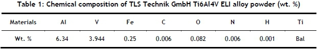
Ti6Al4V (ELI) powder complying with the ASTM F3001 -14, supplied by TLS Technik GmbH, was used to build Charpy impact test specimens using the DMLS additive manufacturing process. The chemical composition of this powder is shown in Table 1.
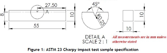
The Ti6Al4V (ELI) Charpy impact test specimens were built on an EOS M280 DMLS machine that is equipped with a 200 W ytterbium fiber laser with a laser diameter of 80 μm. The samples were fabricated with a laser power setting of 175 W, a hatch distance (the distance between two adjacent scan vectors) of 100 μm, and a layer thickness of 30 μm. The Ti6Al4V (ELI) powder particles were of diameter <40 μm. A back-and-forth raster scanning pattern with shift angle of about 67o for each pass was used in the production of the specimens. The substrate and powder materials were similar in chemical composition. Argon gas was used as a protective inert atmosphere in the manufacturing process. The specimens were manufactured to the specifications outlined in the ASTM E23 standard, illustrated in Figure 1.
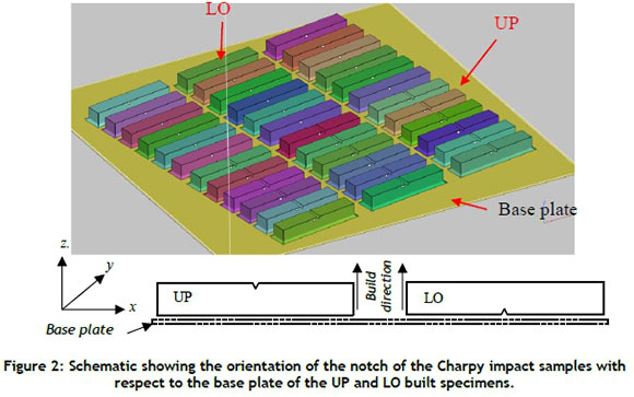
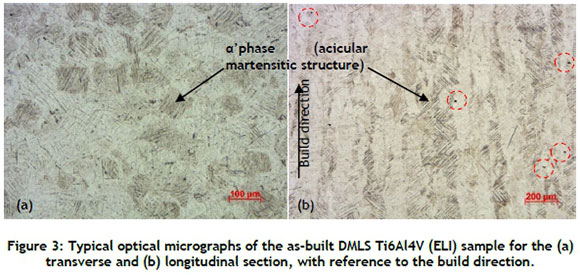
A total of 36 specimens were printed with a V-notch as shown in Figure 1, for use in Charpy impact testing. Half of them were printed with the open end of the V-notch facing the base plate (LO), and the rest with the open end of the V-notch facing away from the base plate (UP), as shown in Figure 2. The DMLS Ti6Al4V (ELI) samples were cut off the base plate by electro-discharge machining (EDM-wire cutting).The microstructure of the as-built samples consisted of a'phase (acicular martensitic structure), as is evident from the micrographs in Figure 3. The prior ß-grains were elongated along the build orientation, which is the heat release direction, while the acicular a'phase formed inside the ß-grain with no specific direction. The a'-martensitic structure results in high tensile strength and low ductility of the parts. Plastic deformation of a'phase is mainly restricted to the basal and prismatic planes of the hexagonal lattice (hcp). Since the a' grains do not form colonies of lath sharing the same orientation, as is evident in Figure 3, the effective slip is confined to a single grain [18]. The microstructure shown therefore gives rise to low elongation to failure, which translates to low ductility. The red circled black spots on the longitudinal section micrograph are process defects (porosity).
2.2 Experimental procedures
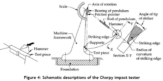
Testing was carried out in the laboratories of the Department of Materials Science and Metallurgical Engineering at the University of Pretoria in South Africa, using a Mohr & Federhaff PSW 80 Charpy impact testing frame. The Charpy impact test was used to determine material toughness at various temperatures by hitting each test specimen with a hammer mounted at the end of a pendulum. The test setup is shown in Figure 4, according to ASTM E23-2007, SANAS 148-1:2013, and ISO 148-1:2009 standards. The hammer used had a maximum capacity of energy of 292 J and a maximum velocity of 5.2 m/s. Each specimen was broken by a single blow of the striking hammer on the swinging pendulum striking at the middle of the specimen, on the surface opposite the open end of the V-notch. After fracturing a specimen, the pendulum rose to a specific height for each specimen, the magnitude of which decreased as the energy absorbed in fracturing each specimen increased.
Consider the angle of inclination of the pendulum arm at the start of falling and rising of the hammer to the vertical axis of rotation as φ and ψ respectively, and the pendulum arm radius as R. The initial height h and final height h'of the pendulum are given by:
From equations 1 and 2 the potential energy (E) of the pendulum at the start, and its potential energy at the final height after fracture (Ef), are given by:
The energy absorbed by the specimen (Eabs) is therefore equal to:

This absorbed energy is equal to the fracture energy of the fractured specimen in each case, and was read off the dial indicator on the Charpy impact testing machine. A V-shaped notch is generally used in a Charpy impact testing specimen to introduce a region of stress concentration in an area with a known minimum thickness/cross-section area, thereby ensuring repeatability of the test results.
Prior to testing the specimens, the Charpy impact pendulum was allowed to swing freely, and the value of the energy absorbed due to friction of the bearings and dials was recorded. The recorded value was used as a correction factor for all the values of absorbed energy that were obtained subsequently for each test specimen. After every test, the pendulum was lifted to the start position, while the measuring dial was reset to the zero position. The tests were conducted at specimen temperatures of -130°C,-100°C,-50°C, 0oC, 27oC, 50oC, 90oC, 150oC, 200oC, and 250oC. All these temperatures, except the temperature of 27oC, which was the room temperature at the time of testing, were obtained by conditioning each specimen through either heating or cooling as appropriate, using the appropriate liquid medium. The medium in the heating bath was constantly agitated and brought to the desirable temperature using a H3760-H hot plate for temperatures above the room temperature. A water medium was used to obtain temperatures between 50oC and 90oC, while an oil medium was used to obtain all other temperatures above this range. Temperatures below room temperature were obtained by adding controlled amounts of liquid nitrogen to absolute ethanol in a beaker surrounded by ice, and then stirring the mixture until a particular desirable temperature was obtained. The specimens were soaked at each desirable temperature with a tolerance of ±2 °C for a period of at least 15 minutes before they were tested. Removing the specimen from the heating or cooling medium and striking it with the impact hammer took, at most, five seconds. This period ensured minimal heat/temperature loss or gain by the respective specimens during testing. The original intention was to undertake three tests at selected temperatures for each set of specimens. However, initial tests demonstrated the need to expand the test range in order to obtain data falling in the horizontal parts of the transition curve. This meant that three specimens were tested at temperatures of -130oC,-50oC, 27oC, 90oC, and 200oC, and a single specimen at the remaining temperatures.
Values of the impact energy absorbed were recorded for all the temperatures and tests done, and the values of mean and standard deviation calculated - the latter in order to determine the scatter of the results obtained.
Figure 5 illustrates the phenomenon of lateral expansion and the measurements that are recommended by the ASTM E23 standard.
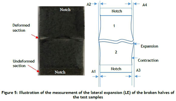
The lateral expansion (LE) or increase in thickness of the specimen due to plastic deformation around the zone of fracture was measured on the broken samples using a digital calliper, as outlined in the ASTM E23 standard and shown in Figure 5. As is stated in ASTM E23, SANAS 148-1:2013, and ISO 1481:2009 [15, 16], if A1>A2 and A3< A4, then LE = A1+A4; or else if A1>A2 and A3=A4, then LE= A1+ (A4 or A3). Similarly, if A1>A2 and A3> A4, then LE= A1+A3.
The fractured surfaces were subsequently cleaned for a period of 15 minutes in an ultrasonic cleaner, using ethanol as the cleaning solvent, and thereafter dried using a strong stream of compressed air.
3 RESULTS AND DISCUSSION
3.1 Impact toughness and lateral expansion
It was determined here that the free-swinging pendulum absorbed about 0.89 J. The values of the absorbed impact energies at temperatures ranging between -130oC and 250oC, taking into account the energy absorbed by the free swing of the pendulum, are presented in Table 2. For the temperatures at which a set of three specimens were tested at the same temperature, the values of the mean and standard deviation of the recorded impact energy were computed and recorded.
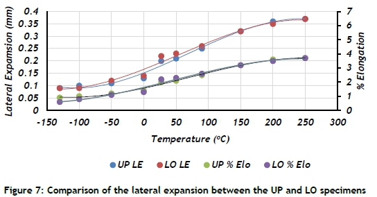
A third-order polynomial curve was used to obtain best lines of fit to the experimental data obtained in these tests. Figures 6 and 7 show the plotted data points and best lines of fit for the as-built (AB) specimens, with the V-notch on the upper (UP) and lower (LO) sides of the respective specimens. The difference between the results obtained from the samples with the V-notches located on the upper and lower sides of the specimens is seen, from the best of fit curves in Figure 6, to increase around the transition temperature, reducing gradually towards the lower and upper shelves of the transition curves.
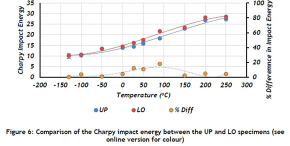
The difference in the curves for the LO and UP specimens demonstrates a clear dependence of the determined values of impact toughness on the location of the V-notch with reference to the base plate of the DMLS machine. The specimens that were printed with the V-notch facing the base plate (LO) show higher values of toughness than the specimens that were printed with the V-notch facing away from the base plate (UP). The percentage difference in impact energy for the LO and UP specimens is small (tending to zero) at low temperatures. This increases gradually with increasing temperature from a temperature of -50oC before starting to diminish again at a temperature of 100oC. The Charpy impact energy curves tend to merge at the lower and the upper shelves. From this observation, therefore, it can be suggested that fracture energy at the lower and upper shelves for this material becomes increasingly more dependent on the temperature than on the orientation of the printed notch.
Upon impact loading on the surface opposite the root of the V-notch, the specimens experience longitudinal direct compressive stress, resulting in Poisson's ratio transverse direct tensile stresses and strains on the surface of impact. This lateral expansion is seen from the best fit curves in Figure 7 to increase with the test temperatures for both the UP and the LO specimens. The curves in the figure have profiles that are similar to those of impact energy shown in Figure 6, complete with upper and lower shelves and transition points. The curves for percentage elongation also exhibit similar profiles for both sets of specimens. The lateral expansions shown, which are expansions to failure, depict a non-linear increase and decrease in magnitude at increasing rates away from both the top and the bottom shelves respectively, above and below the transition temperature.
It has been demonstrated in literature that the magnitude of the residual stress in DMLS-built specimens increases with build directions [21-23]. The work of Mercelis and Kruth [21] showed that the basic residual stress distribution in the Z-build direction for a part removed from the base plate consists of a zone of tensile stresses just below the upper surface. This is followed by a zone of compressive stress in the central region, and a zone of tensile stress at the bottom. The work of Mugwagwa et al. [23] and Van Zyl [23] was consistent with the findings of Mercelis and Kruth [21], and demonstrated that tensile residual stresses were maximal closer to the upper surface. A schematic illustration of the two cases of the UP and LO specimens tested here is shown in Figure 8.
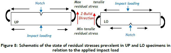
It is evident that, upon impact, the surface bearing the V-notch and the impacted surface of the specimens in both cases experience tensile and compressive longitudinal direct stresses respectively. The effect of residual stress that is related to the build direction, as described here, is to increase the effective tensile longitudinal direct stresses upon impact on the surfaces bearing the notch of the UP specimens by a higher value than for the LO specimens. The effect of residual stresses that are related to the build direction on the impacted surfaces of the specimens is a decrease in the compressive longitudinal direct stress upon impact by a lower value for the UP specimens than for the LO specimens. Therefore, for the same impacting hammer on the swinging pendulum and weight (same imparted energy of 297 J and constant impact velocity of 5.2 m/s, in this case), the longitudinal direct stresses in the specimens will be higher for the UP than for the LO specimens. The UP specimens will therefore fail at lower values of impact than the LO specimens. This inference is supported by the data presented in Table 3, which shows that the average impact energy at room temperature (27oC) for the UP and LO specimens to be 14.41 J and 16.18 J respectively. At this temperature, then, the difference of impact toughness for the UP and LO specimens is equal to 1.77 J (or 12.2% of the lower value). The lateral expansion is also consistent with this trend, giving 2% and 2.2% elongation for the UP and LO specimens respectively - a difference of 0.2% elongation, which is 10% of the lower value. The difference between these elongations may be attributed to the difference in magnitude of the residual tensile stresses with respect to the V-notch. This is higher for the UP specimens than for the LO specimens, thus leading to more opening up of the notch in the former case. The initiation of a crack at the tip of the notch due to impact loading is therefore likely to occur with less and more resistance in the former and latter cases respectively.
The energy absorbed in fracturing the specimens at the lowest temperature used here of -130oC of the test for the as-built DMLS Ti6Al4V (ELI) was recorded as 10.09 J and 10.11 J for UP and LO respectively. These values are 70% and 62% of the values of impact toughness at room temperature for the UP and LO specimens respectively. This is a positive finding, as it indicates that the as-built alloy retains appreciable notch impact fracture toughness even at very low temperatures.
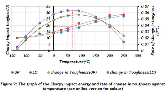
It was difficult to establish the upper shelves of the transition curves using the impact toughness data that was obtained in the present work. However, the gradient of the curves in Figure 6 is seen to diminish at higher and lower temperatures, thus pointing to the existence of upper and lower shelves. It was not possible, therefore, to determine the fracture transition plastic (FTP) temperature - the temperature at which the material exhibits 100% macroscopic ductile failure - within the temperature range used for testing here. Nevertheless, it was possible to determine the DBTT - the lower service temperature of the material. Typically, the DBTT identifies the point at which the percentages of the macroscopic brittle (cleavage) and ductile areas are almost equal. This is referred to as the point of inflection of the transition curve (the point at which the rising gradient of the curve from the lower shelf changes sense and eventually diminishes to zero at the upper shelf). In order to locate the DBTT accurately, the gradients of the fitting curves at the various test temperatures were computed, as shown in Table 3. The values shown in this table clearly demonstrate that the rates of change of notch toughness with temperatures were very low.
The curves of the rate of change in toughness with temperature are shown in Figure 9, together with the related curves of toughness. The curves for rate of change of toughness show that their gradients diminish from maximum values at the two extremities of temperature to zero towards the centre of the curves. The temperatures at which the gradient of the curves for the rate of change in notch toughness becomes zero are the DBTTs of the material. The analysis of Figure 9 can be summarised in Table 4. The most significant value in each case is the DBTT (point of inflection). R2 is the coefficient of correlation for the curve fitting, and indicates the extent of concurrence of the plotted data and the fitted curves. That the correlation coefficients are so high and positive indicates a good positive fit.
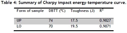
The values in the table show a shift in DBTT to the left (low temperatures) for the LO specimens in relation to the UP specimens, slightly increasing the range of service temperatures at which the alloy can be used without catastrophic failure due to sudden loading. It is also noted that the DBTT toughness of the LO specimens at their transition temperature is higher than that of the UP specimens at their transition temperature. This denotes a higher resistance to failure in the former than in the latter. Clearly, then, the effect of build direction and the resulting residual stresses cannot be ignored.
It is worth noting that as-built (AB) DMLS Ti6Al4V consists of a'phase (acicular martensitic structure), which exists as hexagonal close packed (hcp) crystal structures. The foregoing findings are consistent with the research work of Hashemi [24] and Chernov et al. [25] on the effect of changes in temperature on the toughness of various crystallographic structures. The author suggested that, while body centered cubic (bcc) structures and some hcp structures show extreme changes in their fracture behaviour with changes in temperature, face centered cubic (fcc) structures and some hexagonal close packed (hcp) structures do not. Low temperature embrittlement is a characteristic property of crystallographic structures with high values of Peierls barrier (the force required to move a dislocation within a plane of atoms in the unit cell) and high energy of the elastic interaction of dislocation with point defects. These conditions are met when the direction of slip (direction of the burger vectors) is along the odd axes of symmetry for the crystal lattices. In bcc the direction of slip is <111>; for hcp it is <1123>. Practically all bcc crystal structures belong to this category with the odd axes of symmetry <111 >. It is only in some (but not all) hcp crystalline structures that the odd axes of symmetry <1123> are realised, and so the effect of low temperature embrittlement is revealed. The a'phase (acicular martensitic structure) of Ti6Al4V has a hcp structure similar to that of the α-phase, but one that is slightly distorted and has slipping directions along the axes of an even order (<112 0>) [3]. This results in a smaller Peierls barrier and a weaker elastic interaction of dislocations with point defects in a manner similar to all fcc structures, with axes of an even order <110> [25]. Such slip directions are along closely packed planes. The presence of closely packed planes results in a low Peierls stress, since it is easy for the plane of atoms to slide past each other.
3.2 Comparative analysis of present and other results
In order to assess the performance of DMLS Ti6Al4V (ELI), the results obtained here are presented together with the reported values in various publications for the standard Charpy specimen, as shown in Table 5. It is assumed that, where the details of the test temperatures are not provided in literature, the related tests were performed at conditions of room temperature.
A comparison of the data presented in this table is given in Figure 10.
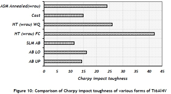
The data presented in Table 5 and Figure 10 clearly shows great variations in the V-notch toughness of Ti6Al4V that is produced using different processes. The research of Yasa et al. [14] obtained lower values for as-built SLM Ti6Al4V than in the current research. Parts prepared by different AM systems may differ slightly in respect of porosity, microstructure, surface roughness, and mechanical properties as a result of the different process parameters of the systems. The Ti6Al4V (ELI) used in aircraft structures is specified in American Society of Metals (ASM) to have a value of Charpy V-notch impact toughness of 24 J. This is approximately 48% higher than that of the values obtained here, while the current values compare favourably with those found for cast Ti6Al4V. The large improvement in the toughness of heat-treated wrought Ti6Al4V (seen in Figure 10) over the parent alloy is due to the microstructural changes associated with the process. The comparatively lower values of toughness obtained in the present work indicate the need for the heat treatment of DMLS as-built Ti6Al4V (ELI) in order to optimise its ductility and strength and therefore enhance its toughness. This also justifies the insistence of the aerospace industry that hot isostatic pressing should be performed on SLM parts.
3.3 Fractography
The resulting fracture surfaces of the specimens that were tested here, a sample of which is shown in Figure 11, exhibit four distinct regions, each representing a specific failure mechanism.
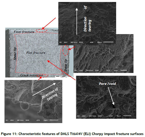
The different regions identified in Figure 11 varied in size with temperature, with the macroscopically flat failure surface (plane strain/cleavage/brittle failure) gradually decreasing in size with increasing temperature. Crack initiation at the root tip occurred by fibrous tearing, producing microscopic dimples that were aligned in the direction of tearing or shear, as shown in the bottom left image of Figure 11. Final failure and separation occurred in the form of ductile shear, evident from the elliptical dimples elongated along the shearing direction, shown in the top right image of Figure 11. The multiple crack initiation sites that are typified by dimples in the bottom left image of Figure 11 spread along the root tip of the notch. The presence of a notch in the specimen introduces multiaxial stresses at the notch, which give rise to planes of both high normal stress and high shear stress. Microscopic examination of the fracture surface of high shear stress (shear lips), shown in the top right image of Figure 11, highlights the presence of elliptical dimples and ridges that are aligned in the direction of shear. Figure 12 shows more images of ductile failure of impact test samples at some selected test temperatures.
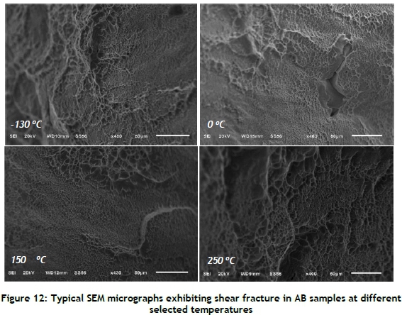
Figure 13 shows the fracture surface at the plane of normal stress (flat surface area). The fracture surface appears macroscopically brittle (flat).
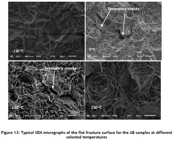
Microscopic examination of the fracture surface in the flat portion of the cup for the AB specimens that were tested at different temperatures, a sample of which is shown in Figure 13, exhibited dimples.
The orientations of these dimples were consistent with shear failure. They exhibited failure zones that were similar to those seen on compressive high strain rate failure surfaces, or the well-known cup and cone failure surfaces of uniaxially loaded tensile ductile specimens. Ductile cracking by the coalescence of micro voids resulted in macroscale brittle fracture (a term used here to designate crack propagation in a direction transverse to that of the existing direct stresses), since the cracking was enhanced by the test specimen geometry (presence of the notch).
Some micrographs in Figure 13 show secondary cracks propagating randomly on the fracture surface. The presence of voids/pores, such as are shown in Figure 11 and Figure 3 (unloaded sample), may form sites for crack growth and propagation due to high stress concentration. The pores/voids shown in these micrographs may be as a result of incomplete melting of the built layers, or the presence of gaseous argon in raw powder during the DMLS process. Similar cases were reported by the research work of Marlo et al. [27].
4 CONCLUSIONS
The following conclusions can be drawn from the foregoing work:
a) The as-built DMLS Ti6Al4V (ELI) specimens that were printed with the V-notch facing the base plate showed higher values of notch toughness than the ones that were printed with the notch facing away from the base plate, over almost the entire testing range of temperatures.
b) The as-built DMLS Ti6Al4V (ELI) specimens showed values of impact toughness at the lowest temperatures of -130oC that were about 70% of the values obtained at room temperature.
c) The Charpy impact toughness of the as-built DMLS Ti6Al4V (ELI) specimens was observed to be temperature-sensitive, showing clear ductile to brittle transition.
d) The presence and distribution of residual stress in the samples gave rise to lower values of the DBTT for the LO than for the UP specimens.
e) Comparative analysis has shown that the values obtained in this work were about 48% lower than the recommended value for use in the aerospace industry.
f) Microscopic examination of the fracture surface shear lips showed the presence of elliptical dimples and ridges that were aligned in the direction of shear even at the lowest temperatures.
g) The area of the flat fracture surface decreased gradually with increasing temperature. Even though this surface appeared macroscopically brittle, failure occurred by a ductile mechanism resulting in the typical cup and cone failure surfaces associated with ductile failure in uniaxial tensile loading.
h) Future work should be aimed at developing an ideal microstructure of DMLS-produced Ti6Al4V (ELI), with optimal strength and ductility thereby enhancing toughness, for application in the aerospace sector, where such mechanical properties are vital for the reliability of the parts.
ACKNOWLEDGMENTS
The active support and funding of the South African Department of Science and Technology through the CSIR for the Titanium Centre of Competence and the Collaborative Program in Additive Manufacturing, Contract No.: CSIR-NLC-CPAM-15-MOA-CUT-01, are gratefully acknowledged. The authors also acknowledge the CRPM for building the test specimens through DMLS. The Department of Mechanical Engineering of the University of Pretoria is also acknowledged for providing the facilities that were used for testing.
REFERENCES
[1] Fischer, C. and Antony, C. 2007. Introduction to contact mechanics, 2nd edition. Springer-Verlag, New York Inc. [ Links ]
[2] Dieter, G. 1986. Mechanical metallurgy. 3rd ed. McGraw Hill, New York. [ Links ]
[3] Lütjering, G. and Williams, J.C. 2007. Titanium: Engineering materials and processes series. Berlin Heidelberg: Springer-Verlag. [ Links ]
[4] Hideki, F., Kazuhiro, T. and Yoshito, Y. 2003. Application of titanium and its alloys for automobile parts. Nippon Steel Technical Report No. 88. [ Links ]
[5] Ikuhiro, I., Tsutomu, T., Yoshihisa, S. and Nozomu, A. 2014. Application and features of titanium for aerospace industry. Technical Review: Nippon Steel Technical Report No.106. [ Links ]
[6] Hollander, D.A., Wirtz, T., Walter, M.V., Linker, R., Schultheis, A. and Paar, O. 2003. Development of individual three-dimensional bone substitute using 'selective laser melting'. European Journal of Trauma, 4, pp. 228-234. [ Links ]
[7] Simchi, A. 2006. Direct laser sintering of metal powders: Mechanism, kinetics and microstructural features. Materials Science and Engineering A, 428, pp. 148-158. [ Links ]
[8] Yadroitsev, I., Thivillon, L., Bertrand, P. and Smurov, I. 2007b. Strategy of manufacturing components with designed internal structure by selective laser melting of metallic powder. Applied Surface Science, 254, pp. 980-983. [ Links ]
[9] Todd, M.M. and Long, M.J. 2015. Mechanical behaviour of additive manufactured, powder-bed laser-fused materials. Materials Science & Engineering A, 651, pp. 198-213. [ Links ]
[10] Molestsane, M.G., Krakhmalev, P., du Plessis, A., Yadroitsava. I., Yadroitsev. I., and Kazantseva, N. 2016. Tensile properties and microstructure of direct metal laser-sintered Ti-6Al-4V (ELI) alloy. South African Journal of Industrial Engineering, 27(3) Special Edition, pp. 110-121. [ Links ]
[11] ASM Handbook. 1993. Materials Park: ASM International. [ Links ]
[12] Buirette C., Huez J., Gey N., Vassel A. and Andrieu E. 2014. Study of crack propagation mechanisms during Charpy impact toughness tests on both equiaxed and lamellar microstructure of Ti6Al4V alloy. Mater. Sci.Eng. A, 618, pp. 546-557. [ Links ]
[13] Lütjering, G. 1998. Influence of processing on microstructure and mechanical properties of (α+Β) titanium alloys. Mater. Sci. Eng. A, 243, pp. 32-45. [ Links ]
[14] Yasa, E., Deckers, J., Kruth, J.P., Rombouts, M and Luvten, J .2010. Charpy impact testing of metallic selective laser melting parts. Virtual and Physical Prototyping, 5(2), pp. 89-98. [ Links ]
[15] Lee, K.A., Kim. Y. K., Yu, J.H., Park, S. H., and Kim, M.C. 2017. Effect of heat treatment on microstructure and impact toughness of Ti6Al4V manufactured by selective laser melting process. Arch. Metall. Mater. 62 (2B), pp. 1341-1346. [ Links ]
[16] Lucon, E. and Hrabe, N. 2016. Instrumented impact tests on miniaturized Charpy specimens of addictively manufactured (AM) Ti6Al4V. Applied Chemicals and Materials Division: Materials Measurements Laboratory, NIST Technical note 1936. [ Links ]
[17] Rzepa, S., Bucki, T., Konopík, P., Dzugan, J., Rund, M. and Procházka, M. 2017. Influence of specimen dimensions on ductile-to-brittle transition temperature in Charpy impact test. IOP Conf. Series: Materials Science and Engineering 179 doi:10.1088/1757-899X/179/1/012063. [ Links ]
[18] Banerjee, D. and Williams, J.C. 2013. Perspectives on titanium science and technology. Acta Materialia, 61(3), pp. 844-879. [ Links ]
[19] ASTM E23-07. 2007. Standard test methods for notched bar impact testing for metallic material. ASTM International, West Conshohocken. [ Links ]
[20] South African National Standard (SANS). 2013. Metallic materials- Charpy pendulum impact test, 2nd edition. SABS Standard division, Pretoria. [ Links ]
[21] Mercelis, P. and Kruth, J.-P. 2006. Residual stresses in selective laser sintering and selective laser melting. Rapid Prototyping Journal, 12(5), pp. 254-265. [ Links ]
[22] Van Zyl. I., Yadroitsava. I., and Yadroitsev. I. 2016. Residual stress in Ti6Al4V objects produced by direct metal laser sintering. South African Journal of Industrial Engineering, 27(4), pp. 134-141. [ Links ]
[23] Mugwagwa, D.D., Matope S. and Venter A.M. 2017. Residual stress distributions within components manufactured using selective laser melting. 18th Rapdasa 2017 Conference Proceedings, pp. 153-165. [ Links ]
[24] Hashemi, S. 2006. Foundations of materials science and engineering, 4th edition. McGraw- Hill, Boston. [ Links ]
[25] Chernov, V.M., Kardashev, B.K., and Moroz .K.A. 2016. Low-temperature embrittlement and fracture of metals with different crystal lattices: Dislocation mechanisms. Nuclear Materials and Energy, 9, pp. 496501. [ Links ]
[26] ASM. Aerospace Specification Metals Inc. http://asm.matweb.com/search/SpecificMaterial.asp?bassnum=MTP643. Accessed on 02/12/2018. [ Links ]
[27] Marlo, S., Tse, Y. and Tuck. C. 2014. The formation of alpha+beta microstructure in as-fabricated selective laser melting of Ti6Al4V. Journal of Materials Research, 29(17), pp. 2028-2035. [ Links ]
Available online 9 Nov 2018
* Corresponding author: amos.mwangi.muiruri@gmail.com

