


Serviços Personalizados
Artigo
 Inglês (pdf)
 Artigo em XML
 Referências do artigo
Indicadores

Links relacionados
-
 Citado por Google
 -
 Similares em Google
Compartilhar

 Permalink
South African Journal of Industrial Engineering
versão On-line ISSN 2224-7890
versão impressa ISSN 1012-277X
S. Afr. J. Ind. Eng. vol.29 no.3 Pretoria Nov. 2018
http://dx.doi.org/10.7166/29-3-2075
SPECIAL EDITION
Evaluating the suitability of Alumide® tooling for injection moulding of different polymers
J. Combrinck*; J.G. van der Walt; G.J. Booysen; D.J. de Beer
Central University of Technology, Free State, South Africa
ABSTRACT
This paper describes the possibility of using laser-sintered Alumide® as an alternative material for producing rapid tooling (RT) inserts. To determine the durability of Alumide® inserts for the injection moulding (IM) process, a product with geometrical features was developed, and Alumide® inserts were manufactured. Polypropylene (PP), acrylonitrile-butadiene-styrene (ABS), polycarbonate (PC), and polyamide 6 (PA 6) were used for IM trials with the Alumide® inserts. From these trials, it was concluded that polymer materials with a processing temperature of about 230 °C, similar to PP and ABS, can be used with Alumide® inserts as RT inserts for the IM process.
OPSOMMING
Hierdie artikel beskyf die moontlikheid om laser gesinterde Alumide® as 'n alternatiewe proses vir die vervaardiging van snel hibried-gietvorms te gebruik. Om die duursaamheid van Alumide® as gietvorms te ondersoek in die plastiek spuitgiet proses, is n produk met spesifieke geometriese vorms ontwerp en Alumide® gietvorms vervaardig. Polipropileen (PP), akrielonitriel-butadiene stireen (ABS), polikarbonaat (PC), en polyamide 6 (PA 6) is gebruik gedurende die plastiek spuitgiet proewe met die Alumide® gietvorms. Resultate van die proewe dui daarop dat plastiek materiale met prosesseringstemperature van ongeveer 230 °C, soortgelyk aan PP en ABS, geskik is vir gebruik met Alumide® gietvorms in die plastiek spuitgiet proses.
1 INTRODUCTION
Product development is a set of activities that transform a concept into a product or service that is usable in the marketplace. Innovative companies use product development to increase demand, or even to create entirely new markets through innovative product design. To remain competitive in the marketplace, product development is essential for the survival of a company [1]. A successful new product can result in profits and growth, while an unsuccessful product can lead to market and financial losses for a company [2, 3].
Almost every product used daily consists of some, if not all, plastic components. More than 70 per cent of components in consumer products are manufactured using plastic materials [4]. Most of these plastic products are produced through the plastic injection moulding (IM) process [5]. For each individual plastic product, a set of steel moulds - into which molten plastic is injected to form the product - needs to be custom-designed and manufactured. These moulds can easily cost tens to hundreds or thousands of Rand and be several thousand times the unit cost of the plastic product manufactured in the mould. The process of designing and manufacturing an injection mould and producing the first plastic product can easily take up to 10 weeks. Injection moulds need to be manufactured to the highest precision, since the moulded product's appearance, shape, size, and strength are influenced by the quality of the moulds. Injection moulds must also be reliable during the production process and repeatedly create products of the same standard. Repeatability and the lifespan of an injection mould are determined by the mould material used, the heat treatment of the mould components, and the machining operations used during the manufacturing of the mould [6]. Conventional manufacturing methods such as computer numerical controlled (CNC) machining and electrical discharge machining (EDM) can be used to manufacture IM moulds. Mould manufacturers must be able to meet close dimensional tolerances within tight time schedules to be economically competitive. It is often difficult to alter completed steel moulds if design changes are required, which is frequently the case during new product development. Small and medium enterprises are often hesitant to take the risk of developing a new plastic product due to the high cost of conventional tooling; and this results in many new product developments not being realised because they are considered too risky to manufacture.
Additive manufacturing (AM), colloquially known as 3D printing, can be used to manufacture a part that is intended for eventual production through IM. This prototype part can be used to test fit, form, and function before capital is spent on steel tooling. However, a limited range of materials are suitable for processing through AM. Parts are often required by product developers in the actual end-use material, such as for mechanical testing or clinical trials [7].
This has led to the development of rapid tooling (RT), where simpler parts of an IM are machined out of aluminium instead of hard-to-machine steel. Geometries of the mould that are complex and time-consuming to machine, and regions that cannot be accessed by conventional machining methods, can be manufactured using an AM process such as direct metal laser sintering (DMLS) [8]. This enables the manufacturing of inserts that would be extremely difficult to produce through conventional manufacturing methods, and of internal features such as conformal cooling, to be included in the tool design. The DMLS inserts are fitted into pockets machined into the aluminium to produce the final RT mould. Alterations to RT tools can be made faster and more cost-effectively than those to steel tools, should design changes be required. While this technique makes it possible to perform production runs in the correct end-use material, the DMLS process is still considered expensive [9].
The PolyJet process, using liquid photopolymer (Objet Digital ABS RGD 515 & RGD 535), can also produce RT moulds for the IM process at a lower cost than with conventional and DMLS tooling. Due to the low heat deflection temperature of the PolyJet inserts (between 58 and 68°C as-built, and 92-95°C after-heat treatment), RT moulds manufactured from this process are not able to withstand extended periods of high injection temperatures (typically between 190 and 300°C for most polymers) during an IM process, thus reducing the lifespan of the moulds. RT inserts manufactured with the PolyJet process are therefore only able to produce 25 to 100 IM products, depending on the polymer injected and the complexity of the mould [10, 11].
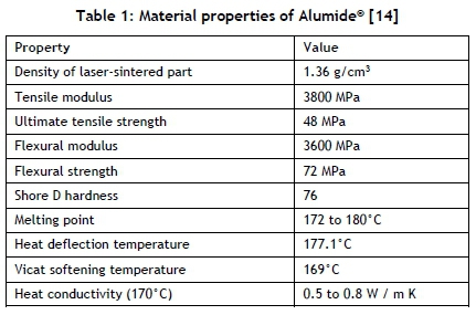
This paper investigates the suitability of laser-sintered Alumide® as an alternative RT material for IM of different polymers. Alumide® is an aluminium-filled nylon material that produces a metallic-looking, non-porous component that can withstand temperatures of about 170 °C. In a recent study [12] it was found that Alumide® inserts can be manufactured in about 50 per cent of the time that it takes to produce the same size DMLS maraging steel insert, and in about 25 per cent of the time that it takes to produce the same size PolyJet insert. The manufacturing cost of an Alumide® insert is about 80 per cent less than for the same size DMLS maraging steel insert, and about 50 per cent less than for the same size PolyJet insert [12]. A typical application of Alumide® is the manufacture of stiff parts with a metallic appearance for applications in the automotive industry, for illustrative models, and for jig manufacture. Alumide® can be finished by grinding, polishing, or coating. An additional advantage is that low tool wear occurs during machining operations such as milling, drilling, or turning the material [13]. Some of the material properties of Alumide® are summarised in Table 1.
2 METHODOLOGY
A test product was designed to test the durability of Alumide® tooling inserts while injecting different polymers. Geometrical features, which are complex and time-consuming to manufacture using conventional CNC machining and EDM processes, were included in the design of the product. These features included sharp internal and external corners, ribs with a thickness of 2 mm and a height of 10 mm, and text features (engraving) 6.15 mm wide and 0.5 mm thick. One set of engraving was extruded outwards, and another set was extruded into the product. Figure 1 shows a CAD model and a product drawing indicating the dimensions of the different geometrical features.
Alumide® inserts for the test product were designed and manufactured through an electro-optical system (EOS) P380 laser sintering machine using standard process parameters as specified by EOS. During the AM laser sintering process of Alumide® parts, significant internal stresses were induced, with an increase in stress as the volume of the part increased. These stresses can result in warpage of the insert during the AM manufacturing process [15]. A method to overcome this problem is to reduce the internal volume of the insert until only a 5 mm shell is left. This technique reduces both the internal stresses and the AM building time. In order to withstand a simulated injection pressure of about 12 to 14 MPa using a 140-ton injection moulding machine during the manufacturing of the geometrical product, shelled inserts were backfilled with Axson EPO 4030 epoxy material. Conformal cooling channels were added to the Alumide® insert design to shorten the required cooling time of an IM cycle and to reduce warpage of the manufactured test products [5, 15]. Oval conformal cooling channels (with primary and secondary axis dimensions of 10.6 mm and 6 mm respectively) 5 mm from the cavity surface were included in the Alumide® insert design. The conformal cooling channels were positioned to obtain the best possible cooling while avoiding insert features, such as screw and ejector pin holes, as shown in Figure 2. The inlet and outlet positions of the conformal cooling channels were placed at locations matching the cooling channel holes of a steel bolster into which the Alumide® inserts were fitted.
To test the suitability of using different IM polymers with Alumide® inserts, the following polymers were used:
• Polypropylene (PP), due to its ease of mouldability and a minimum mould temperature range of 20 to 100°C [16]. PP is also extensively used in appliances and consumer products, and is one of the most widely used polymer materials globally.
• Acrylonitrile-Butadiene-Styrene (ABS) has a melt temperature similar to PP (between 195 and 260°C) and a minimum mould temperature range of 30 to 80°C [16]. ABS is extensively used for electrical enclosures and for automotive and consumer products. These industries often require functional prototypes for testing and verification purposes.
• Polycarbonate (PC) was used to determine the influence of a polymer material with a high melt temperature injected into an Alumide® insert. The recommended melt temperature for most PC material grades is between 270 and 380°C. Due to the high melt temperature, PC requires a higher recommended mould temperature of between 80 and 120°C [16].
• Polyamide 6 (PA 6), to determine the effect of injecting a polyamide material into Alumide®, which is an aluminium-filled polyamide material. PA 6 has a melt temperature of between 225 and 290°C, with a recommended mould temperature of 60 to 100°C [16].
The mould temperature ranges indicated above are based on moulds manufactured from tool steel. Inserts manufactured from an Alumide® material have a lower heat transfer coefficient than inserts manufactured from tool steel (0.5-0.8 W/m K for Alumide®, compared with 24 W/m K for tool steel). Due to the lower heat transfer coefficient of Alumide®, the cooling water temperature was set as low as possible during the IM trials to obtain a mould temperature within the suggested range for PP and ABS. During IM trials with PA 6 and PC, the low cooling water temperature resulted in the solidification of the material before the cavity was completely filled. In order to fill the cavity, the temperature of the cooling water was increased until the cavity was completely filled.
SIGMASOFT® IM simulation software was used to predict the temperatures of the Alumide® inserts after the 20th IM cycle, when the mould would have been at a thermal steady state, or very close to a thermal steady state. After the mould trials, the inserts were scanned with a Kreon Ace 7 axes measuring arm with a Solano Blue laser scanner. The scan data was compared with the CAD files of the Alumide® inserts using Geomagic® Qualify inspection software.
After backfilling and machining operations, the cavity faces of the Alumide® inserts were polished with 320 and 400 grit sandpaper. This was done to remove the stair steps on the surfaces of the geometrical features of the insert that were a result of the AM manufacturing process. The finished inserts were fitted into the bolster, and the complete mould assembly was mounted in a Haixing HXF 268 IM machine. During IM trials, machine process parameters, such as injection speed and pressure, were initially set as low as possible and gradually increased until an acceptable product was obtained. A similar approach was followed during IM trials using ABS, PA 6, and Pc materials.
3 RESULTS AND DISCUSSION
3.1 Geometrical mould trial with PP
The process parameters used during the trial with PP are summarised in Table 2.
Results from the SIGMASOFT® virtual moulding software indicated that the maximum insert temperatures occurred at the insert features. These are shown in Figure 3 for the fixed (Figure 3 A) and moving (Figure 3 B) half of the Alumide® inserts during the IM trials for all the different polymer materials. Due to the small dimensions of these features (19.8 mm x 7.1 mm x 8.6 mm high for the feature shown in Figure 3 A, and 6.5 mm x 5.7 mm x 10 mm high for the feature shown in Figure 3 B), it was not possible to insert cooling channels into the features; and these features were not altered to determine the influence a higher insert temperature would have on the rate of wear.
Figure 4 shows the moving half after 200 IM cycles. The insert feature shown in Figure 4 A did not wear, but started to delaminate. This feature could not be cooled sufficiently due to its size and mould design constraints. The knife-edge corners shown in Figure 4 B did not show any signs of wear.
Results from the SIGMASOFT® virtual moulding software indicated that the insert feature shown in Figure 4 A had a temperature of 179.3°C after the 20th IM cycle. This temperature was slightly more than the melt temperature of 177°C for Alumide®. This slightly higher temperature could cause the delamination of the Alumide® insert feature shown in Figure 4 A.
The Alumide® inserts were scanned after 200 IM cycles using the Kreon scanning arm, and compared with the CAD data of the inserts using Geomagic® Qualify software. The deviation between the scan and the CAD data was consistently about 0.2 mm. This deviation could be from material removed during the polishing of the inserts, which can influence the accuracy of mating surfaces in an assembly of parts manufactured from Alumide® inserts. In order to maintain the dimensional accuracy of an insert and the products manufactured from the inserts, extra material needs to be added to the surfaces that require finishing operations. The extra material will then be removed during finishing operations, such as polishing or CNC machining of the cavities. From the scan results, as shown in Figure 5, there were no geometrical features with a deviation value larger than 0.25 mm. This shows that there was no significant wear on the Alumide® inserts after 200 IM cycles.
3.2 Geometrical mould trial with ABS
The process parameters used during the trial with ABS are summarised in Table 3.
Two hundred IM cycles were completed without any noticeable wear on the fixed half of the Alumide® insert. Due to the higher processing temperature of ABS, the cycle time was increased to allow for solidification of the part before ejection from the mould. Figure 6 shows the moving half after 200 IM cycles.
The insert feature shown in Figure 6 A started to wear after the 10th IM cycle. Wear of this feature continued until the 100th IM cycle, after which it remained constant until the trial ended. This feature could not be cooled sufficiently due to its small dimensions (6.5 mm x 5.7 mm x 10 mm high) and mould constraints. The knife-edge corners shown in Figure 6 B also started to wear. SIGMASOFT® simulation results indicated a temperature of 211.5°C after the 20th IM cycle for the feature shown in Figure 6 A, and 204.7°C for the feature shown in Figure 6 B. These temperatures exceeded the melt temperature of Alumide®, resulting in the wear of these features.
The Alumide® inserts were scanned after 200 IM cycles and compared with the CAD data. The deviation between the scan and CAD data was between 0.2 - 0.3 mm. This deviation could be from material removed during the polishing of the inserts. Extra material needs to be added to the surfaces of the cavities to ensure the dimensional accuracy of the inserts after finishing operations. From the scan results shown in Figure 7, there were no geometrical features (apart from the isolated feature shown in Figure 6 A) with a deviation larger than 0.3 mm.
3.3 Geometrical mould trial with PC
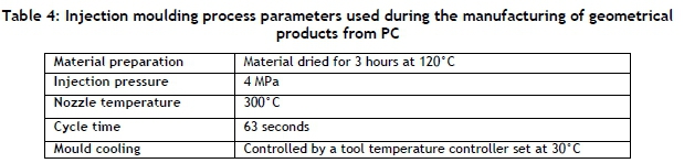
The process parameters used during the trial with PC are summarised in Table 4.
A total of 180 IM cycles were completed before the trial was ended. At the start of the trial, the tool temperature controller was initially set at 20°C. At this temperature setting, the PC material flowing from the nozzle solidified before the cavity was completely filled. The temperature was gradually increased until the cavity completely filled at a temperature setting of 30° C. Within the first couple of IM cycles, wear was detected on the geometrical features of the Alumide® inserts. Figure 8 shows the fixed half of the Alumide® insert after 180 IM cycles. SIGMASOFT® simulation results indicated insert temperatures that exceeded the melting temperature of Alumide® after the 20th IM cycle, resulting in the melting and wear of the features shown in Figures 8 and 9.
Figure 9 shows the moving half after 180 IM cycles. Excessive wear occurred on the geometrical features of the insert, as shown in Figures 9 A and B. SIGMASOFT® simulation results indicated insert temperatures exceeding 214.3°C after the 20th IM cycle for the features shown in Figure 9. These high temperatures resulted in the melting of insert features, causing the excessive wear.
Because it was not practical to remove and scan the Alumide® inserts after a number of IM cycles to determine the wear, the geometrical accuracy of the manufactured products was determined at certain intervals using the Kreon scanning arm. During the IM trial, products produced from the Alumide® inserts were numbered in the sequence in which they were manufactured. The first product was used as a reference for the subsequent products to be compared with using Geomagic® Qualify software. This procedure was used to determine the progression of the wear for the Alumide® inserts.
Figure 10 shows a graphical comparison in Geomagic® Qualify between the reference product and the subsequent products, indicating the wear progression of the insert feature shown in Figure 3 A from the fixed half of the Alumide® insert.
3.4 Geometrical mould trial with PA 6
The process parameters used during the trial with PA 6 are summarised in Table 5.
A total of 150 IM cycles were completed before the trial was ended. Within the first couple of IM cycles, wear was detected on the geometrical features of the Alumide® inserts. Figure 11 shows the fixed half of the Alumide® insert after 150 IM cycles.
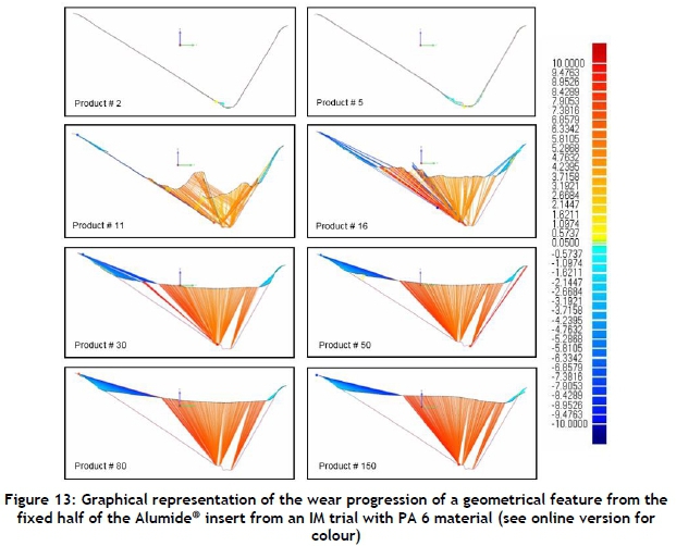
SIGMASOFT® simulation results indicated insert temperatures that exceeded the melting temperature of Alumide® after the 20th IM cycle. These insert temperatures were less than those predicted for the PC material. However, the significant wear on the features could have been due to the melting and bonding of the polyamide in the Alumide® mixture with the injected PA 6 material that was removed with the product from the cavity during the ejection phase of an IM cycle. Figure 12 shows the moving half after 150 IM cycles, with excessive wear to the geometrical features of the Alumide® insert.
Similarly to the SIGMASOFT® simulation of the fixed half, the results of the moving half indicated insert temperatures that exceeded the melting temperature of Alumide® after the 20th IM cycle. The significant wear to the features shown in Figures 12 A and B could again be due to the melting and bonding of the polyamide in the Alumide® mixture with the injected PA 6 that was removed with the product from the cavity during the ejection phase.
Figure 13 shows a graphical comparison in Geomagic® Qualify between the reference product manufactured from PA 6 and the subsequent products, indicating the wear progression of the insert feature shown in Figure 3 A from the fixed half of the Alumide® insert.
4 DISCUSSION
Two hundred IM cycles with PP did not cause any wear to the Alumide® inserts. From these results, it can be concluded that PP is a suitable material to use with Alumide® inserts. IM trials with ABS did not cause any wear to the Alumide® inserts in regions where effective cooling was present.
Regions that could not be cooled effectively due to mould design constraints resulted in wear, as shown in Figure 6 A. This indicates that ABS material can be successfully used with Alumide® inserts if features with high temperatures are identified with simulation software and additional cooling is added to these features. If it is not possible to add cooling to these features, the features can be manufactured from steel or aluminium inserts and inserted into the Alumide® moulds.
Due to the high processing temperature of PC (300°C), the Alumide® material exceeded its melting point of 177°C, causing rapid wear of the geometrical features, as shown in Figures 8 and 9. Due to the rapid wear of geometrical features (within eight injection moulding cycles), PC is not suitable or feasible for use with Alumide® inserts.
Because polyamide is one of the constituents of Alumide®, it resulted in the bonding of the injected polyamide to the Alumide® during the cooling phase of the IM cycle. The Alumide® material that bonded to the injected polyamide was torn from the insert during the ejection of the product from the mould. Fragments of Alumide® material were visible on the products manufactured from polyamide throughout the trial, as shown in Figure 14. From the scan data it can be seen that the wear on the insert continued to increase during the trial, due to the bonding of the polyamide material. This indicated that polyamide is not suitable for use with Alumide® inserts.
5 CONCLUSION
For finishing procedures such as CNC machining, extra material must be designed on to the surfaces to retain the accuracy of the Alumide® insert after machining. A material thickness of 0.2 to 0.5 mm should be added to the surfaces that require finishing operations.
From the IM trials, it is evident that polymers with a high processing temperature, such as PC, are not suitable for use with Alumide® inserts. The high processing temperature increases the temperature of the insert beyond the melting point of the Alumide® material, despite the conformal cooling system inside the insert. This causes excessive wear and deformation of the Alumide® insert. IM trials showed that polyamide materials are also not suitable for use with Alumide® inserts in IM. The injected polyamide material bonds with the polyamide constituent of the Alumide® material, resulting in excessive wear of the inserts. IM trials conducted with PP produced quality products without any significant wear to the Alumide® inserts. ABS can be used successfully with Alumide® inserts if effective cooling can be applied, particularly to regions with large volumes where molten polymer material can accumulate. From the results, it can be concluded that polymer materials with a processing temperature of about 230°C can be used for limited production runs with Alumide® if the insert features can be cooled to a temperature below the melting temperature of Alumide®. Using polymer materials with a processing temperature of about 230°C, it is possible successfully to produce more than 200 products from Alumide® inserts, making it a more feasible option than the PolyJet inserts that are already used in industry for limited production runs.
ACKNOWLEDGEMENTS
Financial support from the South African Research Chairs Initiative of the Department of Science and Technology and the National Research Foundation of South Africa (Grant N 97994), the Collaborative Program in Additive Manufacturing (Contract N CSIR-NLC-CPAM-15-MOA-CUT-01), and technical support from the Centre for Rapid Prototyping and Manufacturing are gratefully acknowledged.
REFERENCES
[1] Emmatty, F.J. & Sarmah, S.P. 2012. Modular product development through platform-based design and DFMA, Journal of Engineering Design, 23(9), pp. 696-714. [ Links ]
[2] Huang, Y., Liu, L. & Ho, J. 2013. Decisions on new product development under uncertainties, International Journal of Systems Science, 46(6), pp. 1010-019. [ Links ]
[3] Hsu, Y. 2011. Relationships between product development strategies and product design issues, Journal of Engineering Design, 22(6), pp. 407-426. [ Links ]
[4] Özek, C. & Çelik, Y.H. 2012. Calculating molding parameters in plastic injection molds with ANN and developing software, Materials and Manufacturing Processes, 27(2), pp. 160-168. [ Links ]
[5] Jahan, S.A. & El-Mounayri, H. 2016. Optimal conformal cooling channels in 3D printed dies for plastic injection molding, Procedia Manufacturing, 5, pp. 888-900. [ Links ]
[6] Kazmer, D.O. 2016. Injection mold design engineering, 2nd edition. Cincinnati: Hanser Gardner Publications, Inc. [ Links ]
[7] Kovács, J.G., Szabó, F., Kovács, N.K., Suplicz, A., Zink, B., Tábi, T. & Hargitai, H. 2015. Thermal simulations and measurements for rapid tool inserts in injection molding applications, Applied Thermal Engineering, 85, pp. 44-51. [ Links ]
[8] Kerbrat, O., Mognol, P. & Hascoët, J.-Y. 2010. Manufacturing complexity evaluation at the design stage for both machining and layered manufacturing. CIRP Journal of Manufacturing Science and Technology, 2(3), pp. 208-215. [ Links ]
[9] Wu, T., Jahan, S.A., Kumaar, P., Tovar, A., El-Mounayri, H., Zhang, Y., Zhang, J., Acheson, D., Brand, K. & Nalim, R. 2015. A framework for optimizing the design of injection molds with conformal cooling for additive manufacturing, Procedia Manufacturing, 1, pp. 404-415. [ Links ]
[10] Zonder, L. & Sella, N. 2014. Precision prototyping: The role of 3D printed molds in the injection molding industry. Stratasys. Available from: www.machinedesign.com_[Accessed 17 May 2017] [ Links ]
[11] Pomager, J. 2015. 3D-printed injection molding: The future of rapid prototyping? Available from: www.meddeviceonline.com [Accessed 25 June 2018]. [ Links ]
[12] Combrinck, J. 2018. Alumide® tooling for limited production plastic injection moulding. Thesis (D. Eng). Bloemfontein: Central University of Technology, Free State. [ Links ]
[13] Combrinck, J., Booysen, G.J., van der Walt, J.G. & de Beer, D.J. 2012. Limited run production using Alumide® tooling for the plastic injection moulding process, South African Journal of Industrial Engineering, 23(2), pp. 131-146. [ Links ]
[14] Alumide® for EOSINTP, EOS material data sheet. Available from: www.eos.com_[Accessed 17 May 2017]. [ Links ]
[15] Dastjerdi, A.A., Movahhedy, M.R. & Akbari, J. 2017. Optimization of process parameters for reducing warpage in selected laser sintering of polymer parts, Additive Manufacturing, 18, pp. 285-294. [ Links ]
[16] Osswald, T.A., Turng, L. & Gramann, P. 2008. Injection molding handbook, 2nd edition. Cincinnati: Hanser Gardner Publications, Inc. [ Links ]
Available online 9 Nov 2018
* Corresponding author: jcombrinck@cut.ac.za

