


Services on Demand
Article
 English (pdf)
 Article in xml format
 Article references
Indicators

Related links
-
 Cited by Google
 -
 Similars in Google
Share

 Permalink
South African Journal of Industrial Engineering
On-line version ISSN 2224-7890
Print version ISSN 1012-277X
S. Afr. J. Ind. Eng. vol.29 n.1 Pretoria 2018
http://dx.doi.org/10.7166/29-1-1802
GENERAL ARTICLE
An automated flexible fixture system for mass customisation
A. Illidge; G. Bright*
Discipline of Mechanical Engineering, School of Engineering, University of Kwa-Zulu Natal, South Africa
ABSTRACT
The need for mass customisation is growing as customer demand for customised products increases. Mass customisation is the production of custom products at mass-produced rates. Current fixture technology does not possess the flexibility required for mass customisation. It was determined, through research, that if mass customisation is to be achieved, a fixture system is required that possesses the following attributes: it accommodates a large variety of part families and geometries; it has automated setups and setup changeovers; it has a semi-automated fixture design; and it provides adaptive feedback during machining processes. A fixture system, known as an automated flexible fixture system (AFFS), was developed that met these requirements. The AFFS was researched, designed, manufactured, and tested. The tests involved determining the AFFS's response to changes in cutting conditions. The AFFS's response to the tests indicated that it behaved normally, for the most part, with higher feed rates and spindle speeds generally yielding higher or more vibrational frequency bands. Further development is required before the AFFS meets commercial standards. However, as a proof of concept it was successful. This paper presents the developed AFFS in more detail.
OPSOMMING
Die behoefte aan grootskaalse op bestelling aangepaste vervaardigde produkte is aan die toeneem. Die bestaande hegstuk-tegnologie beskik nie oor die vermoë om hiervoor voorsiening te maak nie. Dit is bepaal, deur navorsing, dat 'n hegstuksisteem wat die volgende eienskappe besit benodig word om grootskaalse op bestelling vervaardiging te bewerkstellig: dit moet 'n groot verskeidenheid van onderdeel-soorte en -vorms akkommodeer, dit moet van geoutomatiseerde opstellings en opstelling veranderings beskik, dit moet uit n semi-geoutomatiseerde hegstukontwerp bestaan en dit moet voorsienning maak vir aanpasbare terugvoer tydens die masjinering proses. 'n Hegstuksisteem is ontwikkel wat aan hierdie vereistes voldoen. Dié sisteem is nagevors, ontwerp, vervaardig en getoets. Tydens die toetse is die sisteem se reaksie op veranderinge in die masjineringstoestande bepaal. Die sisteem se reaksie tydens die toetse het getoon dat dit meestal normaal reageer het, met hoër voer- en spilsnelhede wat in die algemeen meer vibrasie bandwydtes lewer. Verdere ontwikkeling is nodig voordat die sisteem kommersiële standaarde haal. As 'n bewys van konsep was dit egter suksesvol. Hierdie artikel bespreek die sisteem in detail.
1 INTRODUCTION
The demand for products that are unique to each customer is on the rise, requiring greater advances in flexible manufacturing systems (FMS). The production of different parts at mass production rates in a continuous production cycle is known as mass customisation. Current flexible manufacturing systems are not able to achieve mass customisation due, mostly, to the fixtures that are available [1]. Fixtures are used to locate and constrain parts while they undergo machining processes to ensure that repeatability is achieved [2]. Fixtures are also used to constrain parts for welding and assembly purposes; however, this research focused on their use for machining purposes.
It was determined, through research, that there was a need for a fixture system that could accommodate a variety of different part families and geometries, automatically perform setups and setup changeovers, provide feedback and adaptivity during machining processes, and provide semiautomatic fixture design [3]. This paper presents the research, design, manufacture, and testing of a fixture system that met these requirements, known as an automated flexible fixture system (AFFS). The AFFS consists of five primary components: a locator inventory, a workpiece positioning mechanism, clamps, clamp actuators, and a baseplate. The combination of these components means that mass customisation fixture requirements can be met.
2 LITERATURE
2.1 Flexible manufacturing systems (FMS)
FMS are used to manufacture products that differ from one another, and are typically job shop or small batch operations [1]. FMS use one of two flexibility techniques: machine flexibility or routing flexibility. Machine flexibility refers to the use of high-tech CNC machines, while routing flexibility refers to the use of multiple path routes to produce different products [4]. The restriction on FMS achieving mass customisation and mass-produced customised parts is mostly due to the fixtures that are currently available [1]. Currently, fixtures cannot accommodate different parts rapidly.
2.2 Fixtures
A fixture is a mechanical device that is used to constrain and locate a part so that vibration is minimised and repeatability is achieved during machining processes [2]. They differ from jigs only in the way that they present the workpiece to the cutting tool. A jig moves the workpiece relative to the stationary cutting tool, while a fixture remains stationary relative to the moving cutting tool.
Fixtures consist of three primary components: locators, clamps, and a baseplate [5]. The locators accurately and precisely position the workpiece so that repeatability can be achieved [6]; the clamps push the workpiece against the locators to minimise vibration; and the baseplate is the platform to which the locators and clamps are attached [6]. There are two primary categories of fixtures: dedicated and flexible [1]. Dedicated fixtures are made to serve a single part, while flexible fixtures aim to serve multiple parts.
2.3 Flexible fixtures
There are three types of flexible fixtures: modular, reconfigurable, and conformable [1]. Modular fixtures consist of a number of different components (modules) that can be arranged to suit a relatively large variety of part families and geometries, depending on the module inventory size. The disadvantages of modular fixtures are that they require substantial setup times and fixture design times when new parts require fixing in place, and demand an on-hand module inventory [1]. The use of automated modular fixtures can decrease setup times, but they still require substantial fixture design times; and they do not provide the setup times required for mass customisation.
Reconfigurable fixtures can be reconfigured to accommodate different parts. They provide rapid setup changeovers, and are widely used in reconfigurable manufacturing systems (RMS). The main drawback of reconfigurable fixtures, like RMS, is that they are limited by the number of parts that they can fix in place. They are typically constrained to variations within a part family - a form of flexibility known as customised flexibility. They are therefore not suitable for mass customisation, at least not independently.
Conformable fixtures conform to the geometry of the part that they are fixing in place. Examples include pin matrix and phase-change conformable fixtures [1]. Conformable fixtures can constrain almost any geometry; however, their use as locators requires a high level of technology, and they are typically not as effective as non-conformable locators.
2.4 Fixture design
Fixture design is a four-phase process that aims to meet the fixture requirements of a given part/product. The four phases are: setup planning; fixture planning; unit design; and verification [2]. The setup planning phase involves grouping part features together to form setups, which can be machined together without have to adjust the fixture. The goal is to group the features effectively so that the number of setups and, therefore, the manufacturing lead time (MLT) are minimised [2]. The fixture planning phase involves choosing a fixture configuration for each of the setups to meet the following six requirements: constraining (stability and deformation); tolerance; collision prevention; physical (locator and clamp types); usability; and affordability. This is done through two processes: fixture analysis and fixture synthesis. Fixture analysis is the modelling of the fixture requirements to the available fixture variables. Reducing the number of fixture variables simplifies the fixture analysis process, but results in fewer fixturing options. Fixture synthesis involves selecting appropriate variable values using the models obtained from fixture analysis [3].
The unit design phase involves designing the locators and clamps based on the results from the fixture planning phase. This includes conceptual and detailed design. The verification phase involves verifying that the designed fixture meets the fixture requirements. This is done either by simulation or by physical testing [2].
2.5 Computer-aided fixture design (CAFD)
Computer-aided fixture design is the use of computer software to aid the fixture design process. Current CAFD software does not provide aid for the entire fixture design process, but rather focuses on a particular phase of fixture design. Most CAFD efforts have focused on fixture planning and verification. This segmented approach relies heavily on human interaction and, as result, is the major limitation of current CAFD in facilitating mass customisation [1],[7].
CAFD fixture-planning software assists the user to generate possible fixture configurations, using expert systems and case-based reasoning (CBR). Genetic algorithms can be used to further optimise the selection process. Expert systems rely on extensive knowledge databases to make decisions using an if-then approach. CBR relies on previous cases to provide fixture configuration options. It compares the current fixturing requirements with the requirements of previous cases, and selects the fixture configurations of similar fixture requirement cases as possible fixture configuration options for the current case. CAFD for the verification phase uses finite element analysis (FEA) to verify whether the fixture meets the fixture requirements, such as constraining and tolerance [1].
2.6 Automated flexible fixture systems (AFFS)
If mass customisation is to be achieved, a fixture system that can accommodate a number of different part geometries, automatically perform setups and setup changeovers, semi-automatically perform the fixture design process, and provide adaptive feedback throughout machining processes is required. This is known as an automated flexible fixture system [3].
3 THE DEVELOPED AUTOMATED FLEXIBLE FIXTURE SYSTEM
An AFFS that meets the requirements of a fixture system for mass customisation was designed, manufactured, and tested.
3.1 Accommodation of numerous part geometries
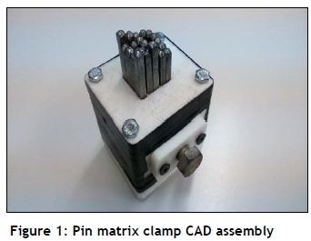
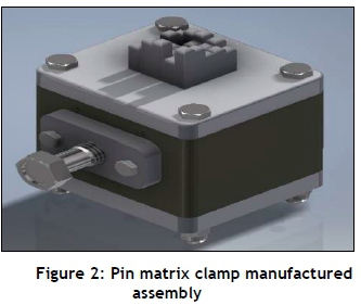
Accommodating numerous part geometries was achieved using conformable pin matrix clamps and a locator inventory. The pin matrix clamps can clamp any surface, greatly simplifying the fixture design process and allowing for the clamping of a number of different parts. The pin matrix clamp computer-aided-design (CAD) assembly and manufactured assembly can be seen in Fig. 1 and Fig. 2 respectively.
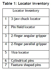
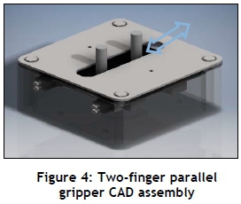
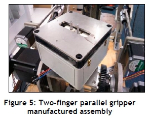
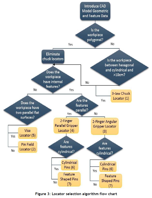
The locator inventory consists of a number of different locator types, each suited to a certain part family. This allowed for the accommodation of numerous part families by meeting their specific locating requirements. New part families can be rapidly introduced by simply replacing the modular locator. The locators that made up the locator inventory can be seen in Table 1. A locator hierarchy was established, giving higher priority to certain locators over others. This hierarchy can be seen in the constructed locator selection algorithm in Fig. 3. This was a preliminary algorithm, and should therefore be further developed and optimised. A locator that was given high priority was a two-finger parallel gripper locator. It uses two internal parallel part features as location points, and leaves the workpiece with a single degree of freedom. This means that a single clamp is required to constrain the workpiece. The two-finger parallel gripper was designed and manufactured, instead of simply purchasing a commercial gripper, in order to reduce costs. A commercial gripper would have provided more rigidity; however, this was deemed unnecessary, as the AFFS was a proof of concept and not a commercial product. The CAD assembly and manufactured assembly of the two-finger parallel gripper can be seen in Fig. 4 and Fig. 5 respectively.
3.2 Automated setup and setup changeovers
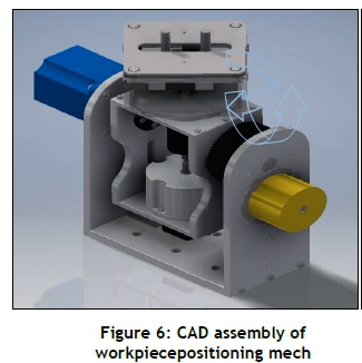
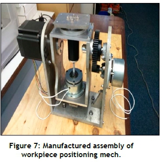
Automated setup and setup changeovers were achieved using a workpiece positioning mechanism and clamp actuators. The workpiece positioning mechanism is a two degree of rotational freedom serial manipulator. This is the device to which the locators are attached, and allows for automated workpiece positioning through geared stepper motors. During machining processes, the workpiece positioning mechanism is locked in position using its two electromagnetic brakes, one for each axis of rotation. The combination of electromagnetic brakes and gear sets produces 20Nm and 296Nm of resistive torque for the Y-axis and X-axis respectively. The workpiece positioning mechanism CAD assembly and manufactured assembly can be seen in Fig. 6 and Fig. 7 respectively.
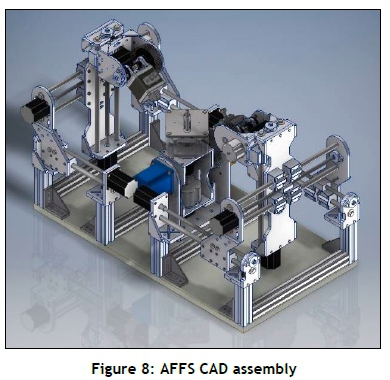
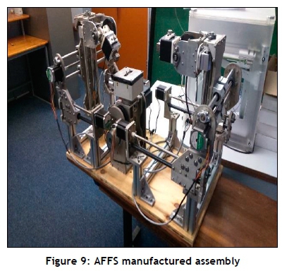
The clamp actuators provide each clamp with three degrees of linear freedom and one degree of rotational freedom. The linear degrees of freedom are powered by stepper motor threaded rod and nut drives. The rotational degree of freedom is powered by a geared stepper motor. The resistive torque of the rotational degree of freedom is produced by an electromagnetic break and a 1:5 reduction gear set. The complete AFFS CAD assembly and manufactured assembly can be seen in Fig. 8 and Fig. 9 respectively.
3.3 Semi-automated fixture design
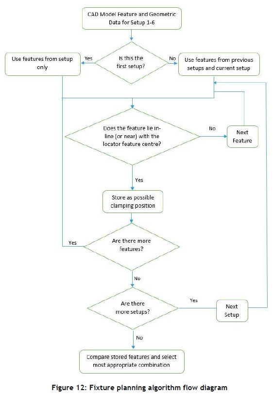
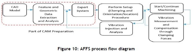
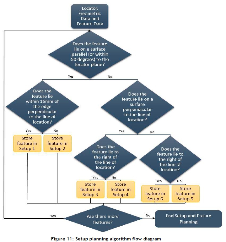
A semi-automatic fixture design was not a focus of this research; however, a general framework was constructed that included two algorithms that aided the setup planning and fixture planning phases. A semi-automatic fixture design involves using CAFD software to aid the fixture designer in the fixture design process, allowing for a more effective fixture design process. The reason that a fully-automated fixture design is not essential is that the fixture design for each new product can be completed and stored before the product is introduced into the production line. This can be done in conjunction with the computer numerical control (CNC) G-code preparation, and forms part of the computer-aided manufacturing (CAM) preparation process. The process that the AFFS follows can be seen in Fig. 10. The setup planning algorithm and fixture planning algorithm can be seen in Fig. 11 and Fig. 12 respectively.
3.4 Feedback and adaptivity
Feedback during machining processes is achieved using a vibration sensor situated on the workpiece positioning mechanism. The vibration sensor measures the vibration that is induced during machining or non-destructive vibration testing, and relays the signal to the microcontroller. The microcontroller performs a spectrum analysis on the signal to determine the dominant vibrational frequencies. These frequencies are compared with the natural frequency of the clamped workpiece. Cutting conditions can then be adjusted to ensure that the vibrational frequencies do not align with the fundamental frequencies, which would cause resonance.
While the cutting conditions can be adjusted to adapt to vibration demands, the adaptability used by the AFFS is in the adjustment of the clamping forces and configurations. Force sensors on each pin matrix clamp allow for the clamping force feedback and adaptability, while the clamp actuators allow for clamping configuration adjustments.
4 CHARACTERISING THE AFFS
The AFFS was characterised in terms of its response to changes in cutting conditions. This was done by measuring the induced vibration with an accelerometer, and performing a spectrum analysis on the signal. This shows the vibrational/acceleration frequencies that are prevalent during the machining processes. The induced vibrations are also compared with the resonant frequencies of the clamped part. The cutting conditions included the feed rate and the spindle speed, for both milling and drilling machining processes.
4.1 Milling
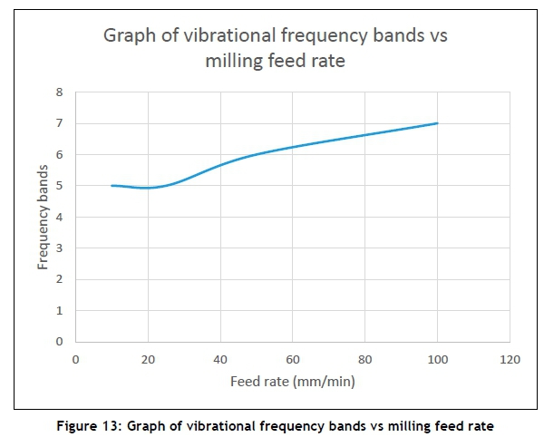
The AFFS was tested in terms of its response to changes in the milling feed rate under a constant spindle speed. The test revealed that increasing the feed rate yields more bands of prevalent frequency, indicating a proportional relationship between the two. The graph of frequency bands vs feed rate can be seen in Fig. 13.
The AFFS was tested in terms of its response to changes in the spindle speed under a constant feed rate. The test revealed that increasing the spindle speed did affect the frequency spectrum; however, the relationship between the two was not apparent.
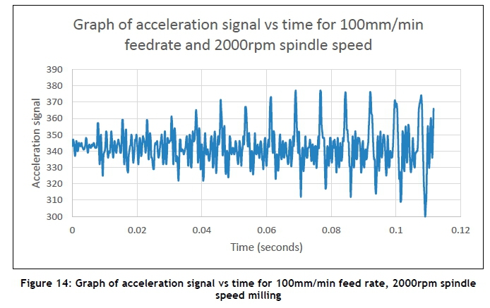
The induced milling vibration amplitude of each feed rate and spindle speed variation grew when the vibrational frequency came close to the resonant frequencies of the clamped part. The natural frequency of the clamped part was 220Hz, a relatively low natural frequency for machining purposes. The harmonic frequencies were therefore 440Hz, 660Hz, 880Hz, etc. An example of the vibration amplitude growth at resonant frequencies can be seen in Fig. 14 and 15.
4.2 Drilling
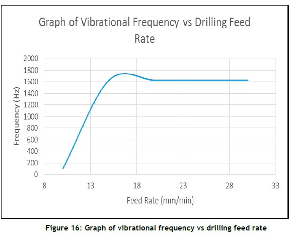
The AFFS was tested for its response to changes in the drilling feed rate under a constant spindle speed. The test revealed that increasing the feed rate yielded higher prevalent frequencies. However, it also revealed a limit to the effect, as seen in the graph of frequency vs feed rate in Fig. 16.
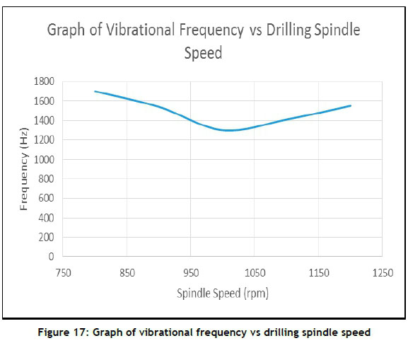
The AFFS was tested for its response to changes in the drilling spindle speed under a constant feed rate. The test revealed an inverse parabolic relationship between the drilling spindle speed and vibrational frequency, as seen in the graph of frequency vs drilling spindle speed in Fig. 17. This indicated that there was an optimal spindle speed, above which the vibrational frequency began to increase. This was likely due to the natural frequency of the cutting tool.
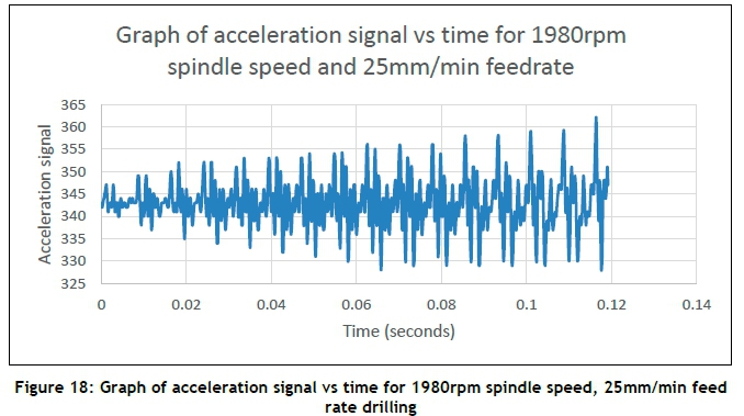
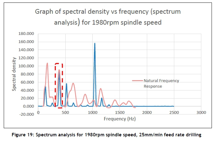
The induced drilling vibration amplitude of each feed rate and spindle speed variation grew when the vibrational frequency came close to the resonant frequencies of the clamped part. The natural frequency of the clamped part, as in milling, was 220Hz, a relatively low natural frequency for machining purposes. The harmonic frequencies were therefore 440Hz, 660Hz, 880Hz, etc. An example of the vibration amplitude growth at resonant frequencies can be seen in Figs 18 and 19.
5 CONCLUSION
The research focused on the issues facing the implementation of mass customisation, and sought to provide a solution. The major issue facing mass customisation in flexible manufacturing systems (FMS) is the inflexibility of the fixtures that are currently available. A fixture system that meets the requirements of a mass customisation fixture was therefore the primary objective of the research. A fixture system that provided automated setups and setup changeovers, accommodated a large variety of part families and geometries, provided the framework for semi-automated fixture design, and provided feedback and adaptability during machining processes was designed, manufactured, and tested. This fixture system was known as an automated flexible fixture system (AFFS).
The AFFS consisted of five components: the locator inventory, workpiece positioning mechanism, clamp actuators, pin matrix clamps, and baseplate to which those components were attached. Each component was designed to meet the requirements of a mass customisation fixture, which is what the developed AFFS did. Testing the AFFS involved characterising it for its response to changes in cutting conditions. The tests revealed that the AFFS mostly behaved conventionally, but also indicated that further development was required before the AFFS could be used as a commercial product. This was to be expected, as the AFFS was a proof of concept and not a final product. Further development is needed to increase the natural frequency of clamped parts by increasing the rigidity of the AFFS. The vibration amplitude growth at resonant frequencies indicated that resonance can be minimised by adjusting the cutting conditions to accommodate the resonant frequencies of the clamped part. The commercialisation prospect and concept for this fixture device requires further research, in which practical case studies should be used as test beds for refinement and performance characterisation within a systems framework. Future research will be structured to implement a methodology based on an application study.
REFERENCES
[1] Wang, H., Rong, Y., Li, H. & Shaun, P. 2010. Computer aided fixture design: Recent research and trends, Comput. Des., vol. 42, pp. 1085-1094. [ Links ]
[2] Boyle, I., Rong, Y. & Brown, D.C. 2011. A review and analysis of current computer-aided fixture design approaches, Robot. Comput. Integr. Manuf., vol. 27, pp. 1-12. [ Links ]
[3] Bi, Z.M. & Zhang, W.J. 2001. Flexible fixture design and automation: Review, issues and future direction, Int. J. Prod. Res., vol. 39(13), pp. 2867-2894. [ Links ]
[4] Shivanand, H.K. 2006. Flexible manufacturing system. New Age International, Delhi, India. [ Links ]
[5] Zheng, Y. & Qian, W.-H. 2008. A 3-D modular fixture with enhanced localization accuracy and immobilization capability, Int. J. Mach. Tools Manuf., vol. 48, pp. 677-687. [ Links ]
[6] Hoffman, E. 2004. Jig and fixture design, 5th ed. Delmar: Cengage Learning. [ Links ]
[7] Yan, X.-T. & Eynard, B. 2008. Global design to gain a competitive edge: An holistic and collaborative design approach based on computational tools, 1st ed. London: Springer-Verlag Limited. [ Links ]
Submitted by authors 10 Jul 2017
Accepted for publication 10 Jan 2018
Available online 31 /May 2018
* Corresponding author Brightg@ukzn.ac.za

