


Services on Demand
Article
 English (pdf)
 Article in xml format
 Article references
Indicators

Related links
-
 Cited by Google
 -
 Similars in Google
Share

 Permalink
South African Journal of Industrial Engineering
On-line version ISSN 2224-7890
Print version ISSN 1012-277X
S. Afr. J. Ind. Eng. vol.28 n.3 Pretoria 2017
http://dx.doi.org/10.7166/28-3-1855
GENERAL ARTICLES
CFD model of laser additive manufacturing process of cylinders
T. TamsaoutI, *; K. KheloufiI; E.H. AmaraI; N. ArthurII; S. PityanaII
ILaser Material Processing Team, Centre de Développement des Technologies Avancées, Algeria
IINational Laser Centre, Council for Scientific and Industrial Research, South Africa
ABSTRACT
A theoretical approach based on a numerical simulation using experimental data is proposed as a contribution to the study of laser-based additive manufacturing by direct energy deposition (DED). The aim is to simulate the stages of layer-by-layer build-ups by considering the induced generated liquid metal in a cylindrical geometry. For normal atmospheric conditions, a 3D model is developed using the finite volumes method to solve the governing equations of the occurring fluid flows and heat transfers. The model is based on the experimental work performed on the LENS system at the Council for Scientific and Industrial Research's (CSIR) National Laser Centre (NLC), where Ti-6Al-4V cylindrical coupons are laser printed and characterised.
OPSOMMING
'n Teoretiese benadering, gebaseer op 'n numeriese simulasie wat van eksperimentele data gebruik maak, is voorgestel as 'n toevoeging tot die studie van lasergebaseerde toevoegings-vervaardiging met direkte energie deponering. Die doel is om die verskillende stadiums van laag-vir-laag opbou te simuleer deur die geïnduseerde vloeibare metaal in 'n silindriese geometrie te oorweeg. Vir normale atmosferiese toestande is 'n driedimensionele model onwikkel om die beherende vergelykings van die vloei en hitteoordrag op te los met behulp van die eindige volumes metode. Die model is gebaseer op eksperimentele werk wat deur die LENS sisteem by die Wetenskaplike en Nywerheids-navorsingsraad (WNNR) se Nasionale Lasersentrum gedoen is. Silindriese Ti-6Al-4V koepons is lasergedruk en karakteriseer.
1 INTRODUCTION
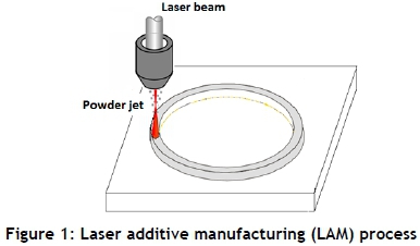
Laser additive manufacturing (LAM) has become an established processing technique to repair and manufacture products in a variety of industrial applications. LAM with powder feeding can be configured with the powder directed by a single side nozzle off-axis powder feed method; but most modern systems use either a co-axial nozzle with an annular outlet passage, or a radially symmetrical nozzle with multiple outlet passages arranged around the laser beam. Particular advantages of this method are omni-directional cladding, and better protection from the ambient atmosphere. Other advantages of the co-axial powder supply are the controlled heating of the powder before it enters the melt pool, and higher powder efficiency [1], [2], [3]. In this process, a laser beam is directed on to a metallic substrate surface to create a moving melt pool and, using a co-axial nozzle, a stream of metal powder of the same or a different type (as in the case of in-situ alloying) is fed into the laser-induced melt pool to form a layer. Repeating laser cladding pass layer by layer, a 3D object can be built up (Figure 1).
Laser metal deposition involves many process parameters and variables that strongly influence the characteristics of the built part. The particular parameters and variables referred to include laser power distribution, beam diameter defocus distance, spatial distribution mode of the laser beam, shielding gas flow, powder delivery gas flow, scan speed, powder feed rate, material properties (absorptivity, melting point, thermal conductivity), and powder characteristics (particle size distribution and particle shape). Physical phenomena associated with laser deposition processes are complex, including melting/solidification, free-surface flow, and laser/metal interaction. The variable process parameters, together with the interacting physical phenomena involved in LAM, complicate the development of process-property relationships and appropriate process control [4]. Optimisation of these processing parameters is necessary to obtain the desired dimensional accuracy and material integrity, and to produce a built part with good strength, while reducing the extent of defects that may occur (porosity, cracks, high residual stress, and dilution). Computational modelling is one such approach that is used to optimise and assess the impact of process parameters, to predict the optimised conditions, to understand the process better and improve upon it, and to obtain quantities that cannot be measured directly in the experiment, such as thermal gradient, local heating/cooling rates, and velocity field in the melt pool.
To simulate the generation of several layers, some authors have used cell activation Error! Reference source not found., which depends on time and space to describe the movement of the front Error! Reference source not found.. These models do not use a predictive approach for the deposited layer dimensions, and do not consider simultaneous and continuous movement of both the laser and the powder deposition zone. Moreover, most of these simulations perform a discretisation of the time t, corresponding to the activation of groups of elements constituting the track. As a result, the deposition front does not move continuously, but follows a sequence, step by step. Moreover, in most of these simulations the fluid flow in the melt pool is neglected, as is the surface tension and thermocapillary force. In addition, these approaches assume knowledge of the geometry of the bead prior to the computation, and require data that can be very difficult to obtain experimentally, especially for multi-layer reloading.
In this work, a 3D transient numerical model using a dynamic mesh approach, based on the resolution of fluid flow and heat transfer equations, is developed. The numerical study was performed in a coordinate system fixed to the base material, in which the geometry of multi-layers is calculated as a function of the process parameters (scan speed, laser energy distribution, powder feed rate, etc.). The model is based on the experimental work performed on the LENS system at the Council for Scientific and Industrial Research's (CSIR) National Laser Centre (NLC), where Ti-6Al-4V cylindrical coupons are laser printed and characterised Error! Reference source not found..
The equations of conservation of energy, mass, and momentum are solved in a coupled manner with the finite volume method used in ANSYS Fluent to discretise the governing differential equations. The geometry of the deposited layers is explicitly described, using moving mesh based on the DYNAMIC MESH tool. It is assumed that the layer is deposited on the intersection of the laser and the powder stream to form a melt pool. The layer thickness is calculated, based on the powder feed rate and elapsed time. It takes into account mass addition, melting and solidification, and the Marangoni effect. Thermophysical properties corresponding to the titanium alloy Ti-6Al-4V are used in the simulation.
2 MATHEMATICAL MODEL
2.1 Assumptions
The present numerical model is based on the following simplification/assumption:
-
The molten metal is assumed to be Newtonian fluid, and the fluid flow in the melt pool is assumed to be an incompressible laminar flow.
-
The metal in the solid and liquid states is isotropic, and has constant and homogeneous properties.
-
Chemical reactions, evaporation, and plasma formation are not considered.
2.2 Governing equations
For the system of interest, the conservation equations for mass, momentums and energy are summarized as follows:
Continuity equation:

Momentum equation:

where v, ρ, p, μ, and g are velocity vector, density, pressure, viscosity, and gravity acceleration respectively. Permeability, K, is assumed to vary with the liquid volume fraction according to the Carman-Kozeny equation [3], derived from Darcy's law:
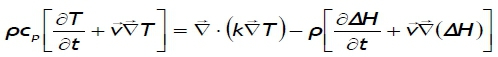
Energy equation:
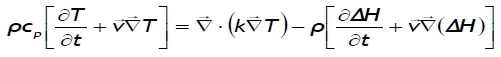
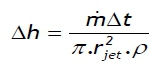
where Cp (J/kg.K) is the specific heat capacity, ΔΗ (J/Kg) the latent heat of fusion, and k (W/m K) the thermal conductivity of the material.
2.3 Boundary conditions
The molten metal surface is subject to tangential shear stress due to thermocapillary or Marangoni convection. The boundary condition associated with momentum balance on the melt pool surface is given by:

where τ is the shear stress, and dσ/dT is the surface-tension gradient along the pool surface. The energy balance on the melt pool surface satisfies the following equation:
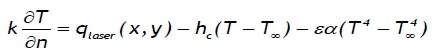
where terms on the right-hand side are laser irradiation, convective heat loss, and radiation heat loss respectively. qlaser is the power of the laser beam, given by :
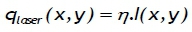
where I(x, y) is the intensity of the laser beam at the location of (x, y):
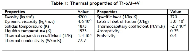
The thermal properties of Ti-6Al-4V used in the simulation are listed in Table 1 Error! Reference source not found.:
3 NUMERICAL RESOLUTION
3.1 Problem geometry
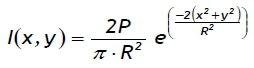
An iron parallel piped sample with the dimensions 20 mm x 20 mm x 2 mm is considered. It is constituted by 229957 hexahedrons - about 251384 nodes. ANSYS Fluent software uses the problem geometry and domain meshing with boundary conditions to solve the corresponding equations by finite volume discretisation. After obtaining the convergence, a post-processing is started to exploit and to present the results. Figure 2 shows the computational domain at t = 0s.
A user-defined function (UDF) written in the C programming language can be interactively loaded and compiled on the calculation procedure during the numerical resolution of the appropriate equations. This allows the standard features of the calculation code to be enhanced. Thus the UDF allows the customisation of the model established in ANSYS Fluent Error! Reference source not found. in order to adapt it for a particular need, such as customising boundary conditions.
3.2 Computation of the generated surface shape
A dynamic mesh capability is used to simulate problems with boundary motion. The building blocks for dynamic mesh capabilities within ANSYS FLUENT are three dynamic mesh schemes: smoothing, layering, and remeshing Error! Reference source not found.. A combination of these three schemes is used to tackle the most challenging dynamic mesh problems. However, for simple dynamic mesh problems involving linear boundary motion, the layering scheme is often sufficient.
The boundary layer smoothing method is used to deform the boundary layer during a moving-deforming mesh simulation. For cases that have a mesh motion UDF applied to a face zone with adjacent boundary layers, the boundary layer will deform according to the UDF that is applied to the face zone. This smoothing method preserves the height of each boundary layer, and can be applied to boundary layer zones of all mesh types (wedges and hexahedra in 3D, quadrilaterals in 2D). On zones with a triangular or tetrahedral mesh, the spring-based smoothing method is normally used. When the boundary displacement is larger than the local cell sizes, the cell quality can deteriorate or the cells can degenerate. This will invalidate the mesh (i.e., result in negative cell volumes) and ultimately will lead to convergence problems when the solution is updated to the next time step.
To circumvent convergence problems, FLUENT collects cells that violate the size criteria and locally remeshes the agglomerated cells or faces. If the new cells or faces satisfy the skewness criterion, the mesh is locally updated with the new cells (with the solution interpolated from the old cells). Otherwise, the new cells are discarded. FLUENT includes several remeshing methods, including local remeshing, face region remeshing, and local face remeshing (for 3D only). The available remeshing methods work for triangular-tetrahedral zones and mixed zones where the non-triangular/tetrahedral elements are skipped Error! Reference source not found..
The new location of the material surface nodes is specified using user-defined function (UDF), which controls the behaviour of the mesh. Note that dynamic mesh UDFs, written and only compiled in C++, are defined using the DEFINE_GRID_MOTION macro Error! Reference source not found..
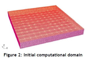
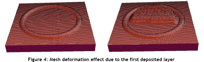
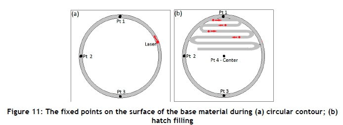
The present paper is concerned with the simulation of the laser fabrication of a cylindrical structure using a special build strategy that is characterised by unique hatching (contour fill) patterns. The outer circumference of the cylinder is deposited first in a counter-clockwise direction, followed by alternating tracks to fill, with laser spot size of 1.4mm and hatch spacing d=0.61mm, in the circle (Figure 3). Figure 4 shows the mesh deformation at a given instance as a function of laser power, the base material, and the injected powder parameters.
The increase in the material height is calculated only for cells where the temperature is equal to or higher than the melting point of the substrate material, as indicated by Toyerskani et al. Error! Reference source not found.
4 NUMERICAL RESULTS AND DISCUSSION
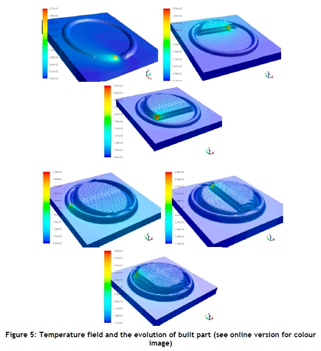
The numerical study was performed on ANSYS Fluent code, in a co-ordinate system fixed to the base material, and a moving laser beam with a constant scanning speed. Figure 5 represents the evolution of the built part and the respective temperature field relating to parameters used for the experimental work performed on the LENS system. In this model, the thickness used for the substrate is 2 mm, and the cylinder shape is 15 mm in diameter, with a laser power of 360 W.)
Figure 5 shows the evolution of the built part and the temperature field of the workpiece for different views. The figure corresponds to a powder feed rate of 2 g/min and a scan speed of 10.58 mm/s. The deposition process illustrates the isothermal lines in the whole domain where the maximal temperature is about T=2750K (2476.84°C) for the first pass, and about 4000K (3726.85°C) for the second one.
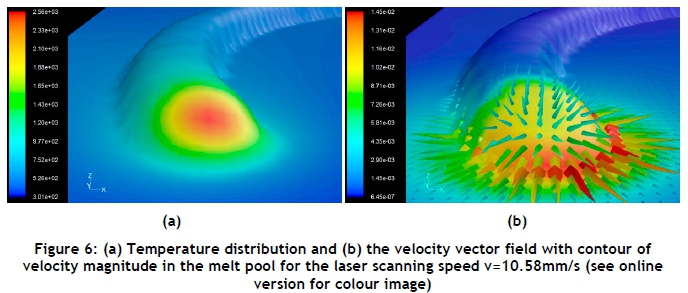
Figure 6 shows the temperature distribution (Figure 6a) and the velocity vector field with contour of velocity magnitude (Figure 6b) in the melt pool for laser power P = 360 W and laser scan speed v=10.58 mm/s during a single layer deposition.
We can distinctly see the molten zone and part of the solidified material due to mass supply to the melt pool. The hottest region is located under the laser beam. The Gaussian power distribution used for the laser yields to energy concentration in a very small region.
The maximum temperature at the surface of the melt pool is about 2560K, indicating that no evaporation occurs (Tv = 3520 K of Ti-6Al-4V). On each side of the peak temperature location, thermal gradients are of the opposite sign, leading to a fluid flow velocity equal to zero at that point due to the Marangoni effect.
The thermo-capillary coefficient, negative for the Ti-6Al-4V, is driving the flow outward from the pool centre to the pool periphery, and results in a shallow and wide pool. One can observe that the melt region is not symmetrical with respect to the travel direction. The convective molten metal flow is responsible for the melt pool spread on the back. Maximum velocity magnitude of the melt flow (Vmax=0.0145 m/s) is observed near the edge of the laser beam, which can be explained by the high gradients of temperature at that region.
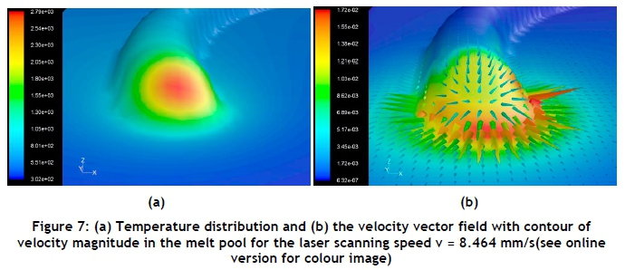
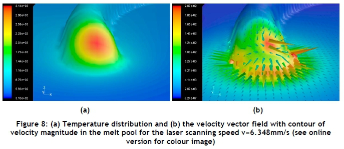
In order to demonstrate the ability of the model, a series of calculations was performed for a reference value of scanning speed of 10.58 mm/s and after a 20 percent (20%) reduction (80%: v=8.464 mm/s) and a further 20% reduction (60%: v=6.348 mm/s) of that value respectively.
The peak temperature in the molten pool produced with the higher velocity was approximately 2500K versus 3150K for the lower velocity. With a significantly greater peak temperature, the temperature gradients along the top surface are substantially larger when using lower velocity. As a result, the Marangoni effect is greater due to the larger spatial variation of surface tension between the middle and the periphery of the molten pool, and the fluid flow velocities within the molten region are larger.
Figure 9 shows the effects of the laser scanning speed on the peak temperature and maximum velocity in the melt pool. An increase in the laser scanning speed will decrease the peak temperature and the maximum velocity. This is because, as scanning speed decreases, the laser material interaction time is extended, as indicated by Arthur et al. Error! Reference source not found..
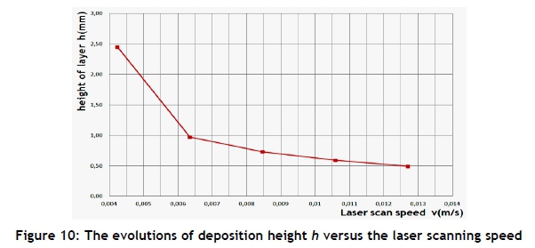
The evolutions of deposition height h versus the laser scanning speed are presented in Figure 10. The height of a deposited clad is inversely proportional to the traverse speed, as indicated by Arthur et al. Error! Reference source not found..
In addition to investigating the geometry of the deposited layer, the model was used to calculate thermal cycles at various locations at the surface of the substrate for laser scan speed v=10.58 mm/s. It is well-known that heating the substrate during buildup is the main reason for the non-uniform microstructure and properties distribution in the part.
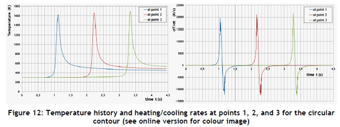
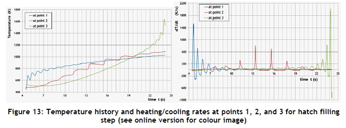
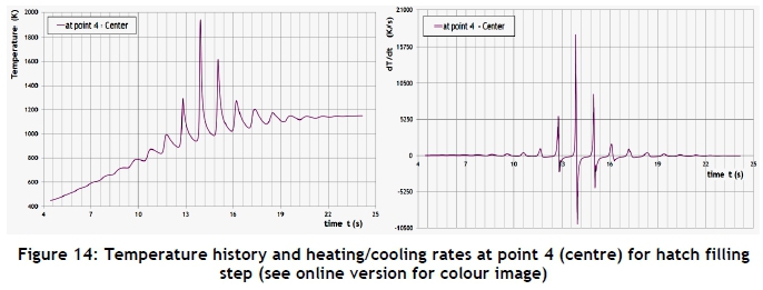
The temperature history for four fixed points on the surface of the base material was saved during the calculation for the first layer. The thermal cycles experienced at these points are shown in Figure 11. Cyclic temperature variations can be clearly observed.
An important accumulation of heat in the already deposited part (cylinder) during the filling stage is observed. This accumulation can be attributed to the continuous nature of the process (no inter-pass waiting time). The juxtaposition of the tracks during the filling stage of the process adds further heating from neighbouring deposits. Calculations of the thermal cycles and heating/cooling rates can be used to understand the impact on micro-structural properties.
5 CONCLUSION
A transient thermal and fluid flow model for the simulation of the deposition of Ti6Al4V on pure titanium has been developed. The model consists of several ANSYS subroutines to simulate the thermal analysis during the laser-powder deposition. The geometry of the deposited layers is explicitly described using moving mesh based on the DYNAMIC MESH technique. One can conclude that a reduction in the laser beam speed caused the peak temperature to increase substantially, which led to much higher fluid flow velocities, an increase in molten pool depth and thermal gradients, and an increase in Marangoni fluid convection due to the decreasing laser velocity, which results in a larger area of the molten pool. An important accumulation of heat in the already deposited part during the filling stage was observed, which can be attributed to the continuous nature of the process. Finally, the calculations of thermal cycles and heating/cooling rates have important effects on the microstructure of the built part, and can be used to understand the impact on micro-structural properties.
REFERENCES
[1] Tucker, T.R., Clauer, A.H and Wright I.J. 1984. Laser-processed composite metal cladding for slurry erosion resistance. Thin Solid Film, 118, pp. 73-84. [ Links ]
[2] Nowotny, S., Richter, A. and Beyer, E. 1998. Laser cladding using high-power diode lasers. ProceedingsICALEO'98, pp. G68-G74. [ Links ]
[3] Lemoine, F., Grevey, D.F. and Vannes, A.B. 1995. Indirect determination of the absorbance during Nd: YAG laser-matter interaction. Laser In Engineering, 4, pp. 273-279. [ Links ]
[4] Hoadley, A.F.A. and Rappaz, M. 1992. A thermal model of laser cladding by powder injection. Metallurgical Transaction B. 23, pp. 631-642. [ Links ]
[5] Neela, V.A. 2009. Three-dimensional heat transfer analysis of LENSTM process using finite element method. International Journal of Advanced Manufacturing Technology, 45, pp. 935-943 [ Links ]
[6] Peyre, P., Aubry, P., Fabbro, R., Neveu, R. and Longuet, A. 2008. Analytical and numerical modelling of the direct metal deposition laser process. Journal of Physics D: Applied Physics, 41, 025403. [ Links ]
[7] Arthur, N., Malabi, K., Baloyi, P., Moller, H. and Pityana, S. 2016. Influence of process parameters on layer build-up and microstructure of Ti-6Al-4V (ELI) alloy on the Optomect LENS™. Paper presented at the 17th RAPDASA Annual International Conference, Vaal, Gauteng, South Africa, 2-4 November 2016. [ Links ]
[8] Boivineau, M., Cagran, C., Doytier, D., Eyraud, V., Nadal, M.-H. and Wilthan, B. 2006. Thermophysical properties of solid and liquid Ti-6Al-4V (TA6V) alloy. International Journal of Thermophysics, 27, pp. 507-529. [ Links ]
[9] ANSYS Fluent. ANSYS Fluent Software: CFD Simulation, (viewed on 18 May 2017, from http://www.ansys.com/Products/Fluids/ANSYS-Fluent). [ Links ]
[10] Toyserkani, E., Khajepour, A. and Corbin, S. 2004. 3-D finite element modeling of laser cladding by powder injection: Effects of laser pulse shaping on the process. Optics and Lasers in Engineering, 41, pp. 849-867. [ Links ]
* Corresponding author ttamsaout@cdta.dz

