


Services on Demand
Article
 English (pdf)
 Article in xml format
 Article references
Indicators

Related links
-
 Cited by Google
 -
 Similars in Google
Share

 Permalink
South African Journal of Industrial Engineering
On-line version ISSN 2224-7890
Print version ISSN 1012-277X
S. Afr. J. Ind. Eng. vol.28 n.3 Pretoria 2017
http://dx.doi.org/10.7166/28-3-1843
GENERAL ARTICLES
A life cycle model for the development of airborne electronic equipment
D. ViljoenI, * ; J. HolmII
IDenel Aeronautics, Kempton Park, South Africa
IISchool of Electrical and Electronic Engineering, North-West University, Potchefstroom, South Africa
ABSTRACT
This paper describes a life cycle model for the development of electronic equipment for use on board military aircraft in the South African context. The life cycle model presented consolidates the activities of systems engineering, safety and certification, and quality assurance. The life cycle model provides a clear-cut and comprehensive framework for the development process in order to streamline planning and control. Concepts fundamental to the definition of a development process are identified and explained, and a generalised life cycle model is derived. Applications of this life cycle model in the description of development processes for airborne electronic equipment are presented.
OPSOMMING
'n Lewenssiklusmodel word hier beskryf vir die ontwikkeling van elektroniese toerusting vir gebruik aanboord militêre vliegtuie in 'n Suid-Afrikaanse konteks. Hierdie lewenssiklusmodel konsolideer aktiwiteite wat vereenselwig word met stelselingenieurswese, vliegveiligheid en lugwaardigheidsertifisering, asook met kwaliteistsversekerings-beginsels. Die model bied 'n duidelike en omvattende raamwerk vir die ontwikkeling van lugwaardige elektroniese stelsels. Konsepte, onderliggend aan die ontwikkeling van hierdie stelsels, was geïdentifiseer en word omskryf en 'n generiese lewenssiklusmodel is afgelei. Toepassings van hierdie lewenssiklusmodel in die beskrywing van ontwikkelingsprosesse vir lugwaardige elektroniese toerusting word aangebied.
1 INTRODUCTION
Electronic equipment intended for use on board aircraft has to meet airworthiness requirements and standards. Airworthiness - i.e., confidence that equipment is suitable for its intended functions and is safe to operate - is established by the meticulous control and scrutiny of data associated with the system design and associated engineering processes, manufacturing and installation processes, operating instructions and procedures, and maintenance aspects of the equipment. All deviations from a certified baseline, including upgrades and modifications to any of these processes and procedures, are subjected to prudent controls. A 'paper trail' of technical decisions, requirements statements, implementation details, validation and verification results, and evidence of adequate control of these must be established and maintained throughout the operational life of the equipment, for each operational version of the affected systems.
Notably, due to implicated versatility, the introduction of embedded digital computers in airborne applications has significantly increased the complexity of airborne electronic systems, thereby compounding the effort to develop these systems to operate correctly and safely.
An airborne electronic system, as delivered to the end user, typically consists of the following elements:
-
Hardware;
-
Software;
-
Support system, consisting of:
o Test and support equipment;
o Operating instructions;
o Training material.
Processes to produce airborne electronic systems must make provision for the creation and integration of all these elements, while meeting airworthiness requirements and complying with the procedural requirements from the particular procurement agency - e.g., Armscor in the South African context. Because the costs associated with the development of these systems are substantial, it is imperative to streamline the methods by which development is accomplished.
A significant number of sources of information, referenced in the literature review below, contribute to the set of references against which airworthy products are developed. The information contained in these sources is of a generalised nature, and typically represents particular points of view, depending on the specific objectives of originators of different publications.
The challenge is to organise all aspects constituting a bespoke development process in a manageable framework, in such a way that the resulting outcomes of the process meet with all relevant airworthiness certification requirements.
A brief summary of a literature review is presented in section 2 of this paper, with the aim of showing why a specific life cycle model is required in this instance.
This article describes a life cycle model for the efficient and effective development of airborne electronic systems, particularly with reference to systems that are developed against a user requirements statement (URS) applicable to a specific aircraft type, as opposed to systems developed in response to a market-driven set of generic requirements.
This paper demarcates the scope of processes to which the life cycle model applies, and introduces concepts particular to the development of safety critical systems containing embedded software. A life cycle model suitable to the development of airborne electronic systems is then described, and it is shown how systems engineering and quality assurance objectives are unified and achieved by means of the structure of the life cycle model. Finally, applications of the life cycle model are presented.
2 SUMMARY OF LITERATURE REVIEW
A comprehensive literature study relevant to the process description presented in this paper was conducted under the following headings:
-
'Classic' systems engineering references;
-
Contemporary systems engineering standards;
-
Airworthiness recommended practices;
-
Academic literature.
Significant findings from this literature study are summarised below.
2.1 Classic life cycle models
The classic systems engineering references include Blanchard and Fabrycky [1], MIL-STD-490A [2], MIL-STD-1521B [3], MIL-STD-498 [4], and RSA-MIL-STD-3 [5].
Salient aspects of the methods described in 'classic' systems engineering references include:
-
The standards promoted processes that were document-based and very prescriptive, down to low level details. The prescribed processes are not compatible with modern database-centred requirements for management systems;
-
A rigid breakdown of the system in different levels of hierarchy, with a markedly different approach to the lifecycle at each level of hierarchy, including the types of documents to be generated at each level, was described;
-
The process included the development of a particular set of prototypes that were associated with specific decision points within the lifecycle. These decision points were controlled by means of well-structured reviews, associated with pre-defined baselines. This approach is not optimised for the development of systems employing embedded software;
-
There is no clear differentiation between project management and technical processes. This complicates the planning of the engineering effort.
2.2 Contemporary life cycle models
Systems and software engineering standards reviewed in the literature study include ISO/IEC 15288 [6], IEEE 1220 [8], EIA-632 [14], and IEEE 12207 [9].
An assessment of these contemporary standards indicated that, although there are superficial similarities between the tasks and activities described by these standards, the detailed definitions of the required process activities differ significantly between standards. This observation corroborates the assertion that there is no universally accepted description of the activities and tasks required for the engineering of systems.
Significant notions about the engineering of systems, as described by the contemporary standards, are:
-
The focus is on 'what should be done' rather than 'how it should be done', which allows the process designers to select the optimal methods to achieve specific outcomes;
-
A 'system-of-systems' approach is advocated, which provides for the iterative use of generic life cycle models at all layers of the system hierarchy. This contrasts with the hierarchies described by the 'military' approach, and simplifies the process design significantly;
-
The standards describe the development of a 'first article' that fully represents the final product from the outset;
-
A separation of technical and project objectives is promoted. This simplifies the formal description of an engineering process.
2.3 Aerospace industry recommended practices
The literature study included a review of aerospace industry recommended practices RTCA/DO-178C [1], [11], RTCA/DO-254 [12], and ARP4761 [13].
According to ARP4754A [11], a development project must incorporate the following elements in the development process:
-
The process and methods to be used for the system architecture development, integration, and implementation must be clearly described;
-
A safety programme that consists of the safety activities related to the development of the system;
-
Requirements management - capturing and managing requirements;
-
Validation - showing that requirements and assumptions are complete and correct;
-
Implementation verification - processes and criteria are applied to show that the implementation satisfies its requirements;
-
Configuration management - the description of key development-related configuration items and their management;
-
The process assurance process - ensuring that the defined practices and procedures to be applied during system development are followed;
-
Certification - the process and methods used to achieve certification of the system.
The eight points above are fundamental to the development of airborne electronic equipment. It follows that a process design that is based on the life cycle model described in this paper must be structured such that it will unambiguously show the associations with these points.
Importantly, it must be noted that recommended practices regarding the systems safety process [13] promote a requirements-based development process, which significantly constrains the selection of a life cycle model. Thus the process design based on the life cycle model presented in this paper must be a requirements-based process.
2.4 Academic publications and literature
A considerable number of academic publications and other sources in the literature were reviewed in the literature study. Notable among these were the INCOSE Systems Engineering Handbook [14], BKCASE [15], Beck, Kent et al. [16], Larman and Basili [17], Royce [18], and Estefan [16].
Important findings from the review of the academic literature are summarised below.
The INCOSE Handbook [14] identifies four types of lifecycle approaches: (i) plan-driven methods, (ii) incremental and iterative development (IID), (iii) lean development, and (iv) agile development. The BKCSE [15] presents a number of lifecycle models, but differentiates between pre-specified and evolutionary classes of models.
Examination of these lifecycles shows that there are essentially only two fundamental classes of approach: planned and structured development, and less structured development. As pointed out in the INCOSE Handbook, a planned approach is characterised by adherence to specified processes that direct the development effort from requirements through design to finished product, and attention is given to the completeness of the documentation, traceability from requirements, and verification of compliance with requirements. It was shown in the study of aerospace-recommended practices that this approach is mandatory when developing airborne electronic systems.
A number of lifecycle models can be implemented in a planned and structured approach. The classic military development lifecycle mentioned in 2.1 could be described as having employed a pre-specified, sequential single-step lifecycle model, supported by the use of prototypes.
The incremental implementation of functionality is described by the BKCSE [15] as a "pre-specified, multi-step" model, and two versions of the model are presented: either delivering incremental blocks of functionality, or executing the development in 'blocks', but delivering the system after integration of the final block into the system. Both of these versions can be considered in the development of airborne electronic equipment, depending on the operational requirements of the user.
Consequently, in terms of the classifications described by the BKCSE [15], the lifecycle model appropriate to the development of airborne electronic equipment has to be a pre-specified, multistep model.
3 APPLICABILITY
As a first step in the development of a life cycle model for a particular engineering process, the scope of the tasks to which the life cycle model applies must be established.
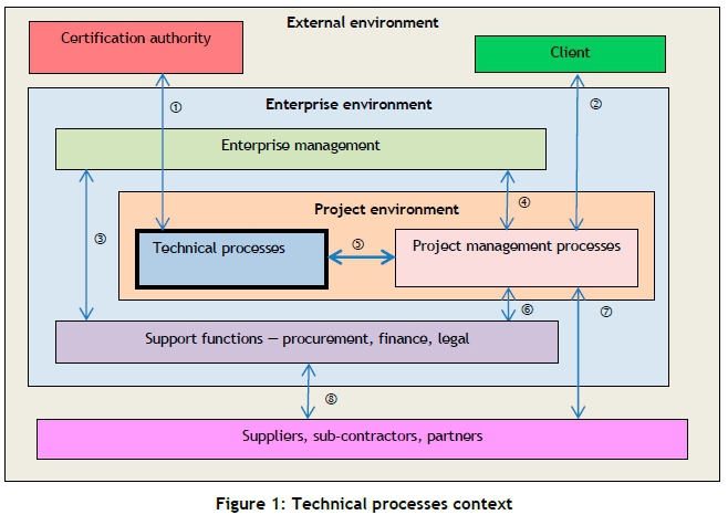
3.1 Technical processes context
The functional groups associated with a project with the objective of developing a technical system are shown in Figure 1.
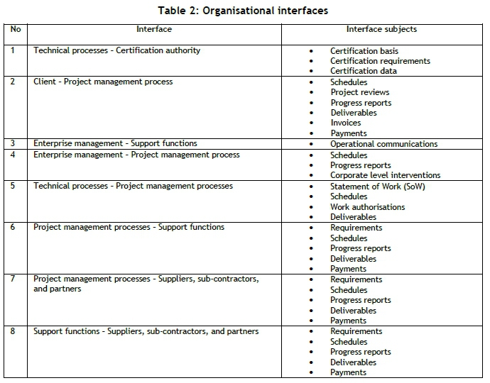
The interfaces between functional groups shown in Figure 1, and aspects controlled via these interfaces, are shown in Table 1. This breakdown helps to simplify the definition of the scope of the technical processes, as it categorises all activities associated with a development project.
The context of technical processes within the greater operating environment is also shown in Figure 1. In this representation, the technical processes only interact with project processes and with the airworthiness certification authority.
The technical processes encompass activities of technical planning, requirements management, system design, prototyping and modelling, procurement and integration of first article components, software coding, system and software integration, and verification. These activities include specialisation areas such as airworthiness, safety, reliability, security, maintainability, supportability, human factors, electromagnetic compatibility (EMC), flight testing, and the application of other subject matter expertise.
The process described in this paper is concerned with the development of the system up to production standard. The production preparation and actual production processes are excluded.
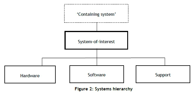
3.2 System of systems concept
Contemporary systems engineering standards promote the concept that life cycle processes should be applied recursively to a system-of-interest and its system elements on all layers of the systems hierarchy, as well as to the development of associated enabling systems, as shown in Figure 2.
The life cycle model described in the sections that follow therefore applies to the development of each of these elements.
4 ESSENTIAL CONCEPTS
Concepts relevant to the development of airborne electronic equipment that had to be considered in the definition of a life cycle model are explained below.
4.1 Process produces a '1 st article'
The artefact representing a verified and validated system-of-interest that the development process generates is fully representative of the 'production' units. This differs from more conventional views where a number of formal prototypes (e.g., XDM, ADM, EDM, PPM) were developed towards the final product. This methodology is feasible due to the specific nature of modern electronic equipment containing embedded software. The use of modern design tools makes it possible to design enclosures and electronic boards, and to validate these designs prior to manufacture without resorting to physical prototypes in all cases. The software development process prescribed by, for example, RTCA/DO-178C [1], also motivates a top-down process, without resorting to 'prototyped' code. The artefact produced by the formal development process is a 'first article'. Therefore, it is important that the life cycle model accommodates this 'first article' concept.
4.2 Development assurance level
For airborne electronic systems, assurance of the integrity of a product is obtained by establishing confidence that errors in the requirements and implementation have been detected and removed. This confidence is achieved by providing objective evidence of adherence to a systematic engineering process directed at finding these errors. The rigour by which this process is executed depends on the safety objectives for the product. Documented evidence of adherence to a defined process is used to substantiate claims of airworthiness - i.e., establishing confidence that the developed system is safe for use [2], [3].
Development assurance levels are assigned as follows: Level 'A' processes correspond with functions associated with catastrophic failures, level 'B' with hazardous failures, level 'C' with major failures, level 'D' with minor failures, and level 'E' when no safety implications were identified. The different levels of design assurance are achieved by the levels of rigour of the development and verification activities as prescribed in the standard.
An important fact to consider is that software does not 'fail' in the traditional sense, but rather contains undetected errors. The processes as directed by RTCA/DO-178C [1] aim to provide confidence that errors that may lead to failure events are detected and removed. This is also achieved by the rigour of the development and verification effort. Software levels are allocated that are equivalent to the design assurance levels - that is, level 'A' software is required for the implementation of functions where failures lead to catastrophic events, and similarly for lower levels. The difference between the various software levels is the intensity of verification and validation, and the degree of independence with which verification and validation tasks are executed.
This can be summarised as follows: for software and 'complex' hardware, the confidence that the system is safe for use is established through evidence that the development process supported sufficient measures to ensure that all safety-related errors were detected and removed. This evidence is documented in validation and verification records. Accordingly, the assurance level (development of software) is achieved by virtue of the rigour of the development process, supported by corroborating evidence.
4.3 Verification and validation
As indicated above, validation and verification processes form the basis of the development assurance processes.
In the context of this paper, the term 'validation' firstly implies the process by which the correctness and completeness of life cycle data and other process outputs are ensured. Requirements are to be validated before the implementation of those requirements is begun. For requirements that can be traced to requirements in higher layers of the systems hierarchy, traceability data serves as validation. For derived requirements, validation evidence is provided by documenting the rationale behind each requirement. The demonstration of compliance with a standard is another example of a validation activity. Other typical validation activities include design reviews and document inspections, where the objective of a review or inspection is to affirm the integrity of a design or a document (as opposed to reviews that measure progress against a schedule, which is a project management activity).
Note that, according to the reasoning presented above, the general quality management practice of inspection and approval of life cycle data can be considered as a validation activity.
In the life cycle model described in this paper, 'verification' denotes the process of providing evidence that a requirement has been satisfied by an element (or arrangement of elements) of a synthesised system. Verification can be performed by means of tests, analyses, and reviews. The verification method shall be selected on the basis of practicality and appropriateness. Demonstration that a synthesised system meets with a set of requirements is consequently a verification task.
This distinction between 'validation' and 'verification' is very important with respect to the life cycle model described below, and leads to significant simplification of the representation of the development process.
5 LIFE CYCLE MODEL SYNTHESIS
5.1 'Process function' concept
A widely accepted practice for describing processes, whether executed by humans or by machines in functional terms, is IDEF0. The name is derived from 'ICAM definition for functional modelling', where ICAM is an acronym for 'integrated computer aided manufacturing' Error! Reference source not found.. The methodology is used to a great extent in the INCOSE Systems Engineering Handbook [8]. The IDEF0 model building block expresses a process as a function or collection of functions that produces outputs from a set of inputs, using the indicated mechanisms, and controlled by the designated controls, as shown in Figure 3. This concept is briefly reviewed for the sake of completeness.
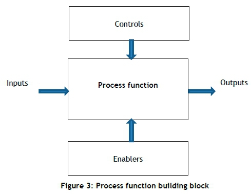
The elements of a development process, also referred to as 'development process activity', can formally be represented as sets of interconnected process functions. Each process function acts on a set of inputs to produce a set of outputs, and each process function is supported by a set of enablers and subject to a set of controls. As is known, outputs of a prior process function become inputs to a succeeding process function.
This concept of 'process functions' provides a convenient basis for the description of the key elements that constitute a development process.
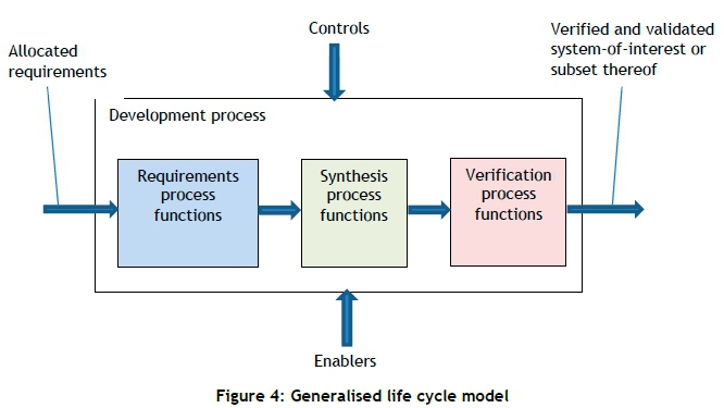
5.2 Generalisation of life cycle processes
A significant generalisation can be made: that activities constituting the development life cycle processes are classified into three main activity focus areas: requirements, synthesis, and verification processes.
5.2.1 Requirements processes
The objectives of requirements processes are to determine the functional and performance requirements of the system-of-interest and to identify implementation constraints. Other required attributes of the system-of-interest are also defined, such as reliability qualities. All these are described clearly and unambiguously as a set of functional and non-functional requirements.
5.2.2 Synthesis processes
The synthesis processes develop architectural and detailed designs, and generate and/or procure hardware elements and software code. It is evident that these processes implement requirements. The processes also include all hardware and software integration actions to produce the system characterised by the requirements.
5.2.3 Verification processes
The purpose of verification processes is to obtain objective evidence to prove that the system produced by the synthesis processes meets with the requirements produced by the requirements processes. Development is concluded when verification evidence with respect to contractual and certification requirements is formally accepted and all discrepancies have been resolved.
5.2.4 Representation in terms of process functions
The development life cycle can be represented in a high level process function presentation, as shown in Figure 4. Each process function receives inputs and produces outputs; each process function (or selected group of process functions) is subject to controls; and the process function is executed using a set of mechanisms or enablers.
5.3 Development process controls
The objectives of the development process controls are, firstly, to ensure that authorised tasks are performed with respect to life cycle data items of interest and to manage the integrity of the data; and, secondly, to confirm that tasks have been executed correctly upon completion of each task individually and collectively as a process.
5.3.1 Configuration management as a process control mechanism
An established configuration management (CM) process meets with the first control objective stated above. In particular, a change control process associated with a specific baseline structure and change authorisation methodology will ensure that no unauthorised changes will be performed on controlled life cycle data, and that appropriate changes will only be implemented on correctly identified data items.
5.3.2 Quality assurance as a process control mechanism
This objective is achieved through activities that ensure that the outputs of activities meet with the requirements and standards applicable to those activities. These are the validation processes associated with specific tasks and outcomes. These validation tasks include all the activities aimed at confirming the correctness of the outputs of the process functions, and the generation of evidence of the validation results. Importantly, note that the validation of process function outputs applies to each process function (task) that forms part of a development process.
5.4 Enabling mechanisms
An enabling system "supports a system-of-interest during its life cycle stages, but does not necessarily contribute to its function during operation" [5].
5.4.1 Configuration management as an enabling mechanism
Although CM is identified as a control mechanism, aspects of the CM system can also be regarded as supporting mechanisms - i.e., storage and management of document templates, verified reusable code blocks and designs, and the assurance of the availability of accurate project data from a central data repository.
5.4.2 Methods and tools
Methods and tools reside under the classification of enablers or mechanisms [19]. Tools include PLM systems, computer aided design tools, integrated development environments for developing software code, and integration and test systems.
5.4.3 Technical plans
Technical plans provide guidance about the methods and procedures to be followed and, more importantly, define or identify the criteria against which the outcomes of tasks can be evaluated, thus enabling the validation process. Note that these plans include certification-related plans; implicitly, therefore, the certification liaison process can be regarded as an enabling process.
5.4.4 Modelling, simulation, and prototyping
Concepts such as rapid prototyping and simulation can be used in support of, for example, refinement of requirements or testing design trade-offs. Hence prototypes and simulation can be viewed as entities of enabling systems, as long as they do not form part of the formal definition of the product.
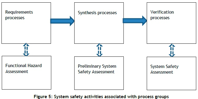
5.5 Associations with the system safety process
Considering the system safety process described in SAE ARP4761 [4], the associations shown in Figure 5 can be made.
A functional hazard assessment (FHA) reviews the functional requirements of the system, including derived functional requirements, to determine the severity of the consequences of failures for specified functions. These severities define design objectives that mitigate the risks associated with identified functional failures. It is important that any changes to functional requirements, or to new derived requirements, should be subjected to the FHA process.
A preliminary system safety assessment (PSSA) evaluates the system's architectural design to determine whether that design contains sufficient redundancy, and to determine whether development assurance levels are commensurate with the safety objectives determined by the FHA.
The objective of a system safety assessment (SSA) is to verify that the safety requirements have been met.
The system safety process elements are then incorporated as process functions in the process synthesis.
5.6 Unification of quality management and systems engineering objectives
It is important to understand that, in terms of the development of systems, objectives from quality assurance and systems engineering are simultaneously achieved by defining the process in terms of a logical combination of process functions, and ensuring the comprehensive validation of the outputs at the level of each process function. This statement can be made because both disciplines require a process of defining and validating requirements, and providing an assurance that the outputs of tasks are validated.
If the validation tasks have been performed with sufficient independence, the objectives of quality, process, and design assurance - as recommended by systems engineering and airworthiness references - are implicitly achieved.
6 APPLICATION OF THE LIFE CYCLE MODEL
The definition of this generalised life cycle model facilitates a view on the development process that simplifies the understanding of typical conundrums associated with the development of complex systems. Some typical difficulties that have proved problematic to manage in practice are described below.
6.1 Baselines
The life cycle model presents a clear set of boundaries inside which development can be controlled by means of baselines. Three baseline types have been identified: requirements, verification, and product baselines.
Once the requirements for a system have been validated, these requirements form references for the synthesis and verification processes. It follows that validated requirements statements cannot be altered indiscriminately, as this would affect traceability between the requirements and the implementation. Therefore, requirements must be under formal change control from the time validation has been completed, which implies baselining requirements by means of a configuration management process. For the purpose of the process design described in this paper, this baseline is termed the 'requirements baseline'.
The synthesis process group produces an integrated system, containing electronic hardware and software and enabling products. Upon completion of the synthesis process, the system is subjected to a verification process to demonstrate compliance with requirements. It is important to understand that the system or life cycle data describing its attributes cannot be modified while the verification process is in progress. If the design of the system is altered in order to correct a deficiency, some system attributes may change, which would imply that the behavioural characteristics of the system may have been affected and that previous test results on the system may be rendered invalid. Therefore, it is prudent to ensure that the system contains the least possible number of defects at the stage when it is subjected to verification tests.
A practical approach is to subject the system to dry runs of verification tests before formal tests are performed. These dry run tests may detect latent defects that had not been detected during integration testing, and may also identify errors in test procedures that can be corrected prior to formal verification testing. At the point where the validation of all outputs of the synthesis process and the validation of test cases and procedures have been completed, the verification baseline is established.
Following the establishment of the verification baseline, the system is subjected to formal verification tests to show that it meets requirements. The product baseline is established upon completion of all verification tests. The product baseline represents the system when it is declared fit for operational use, and this baseline is referenced in the aircraft's Certificate of Design (CoD).
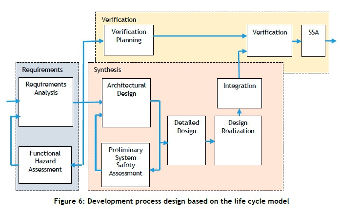
6.2 Development process design
An example of a design of a development process that is based on the life cycle model is presented in Figure 6. This example shows the major process functions that comprise the requirements, synthesis, and verification groups. An important feature of this process design is that verification planning commences at a stage prior to the establishment of the verification baseline, and that the outputs of the verification planning process function are applied to the integration process function - that is, the verification tests are executed on the integrated system prior to establishment of the verification baseline, in so called 'dry runs' of the tests. The difference between these integration tests and the eventual verification tests is that integration tests are aimed at removing all errors in the design as well as errors introduced during the design realisation and integration processes, whereas verification tests demonstrate compliance with requirements. These 'dry runs' also aid in the removal of errors in the documentation describing the verification procedures and cases.
6.3 Parallel execution of verification tests
A consequence of performing tests on an established baseline is that verification tests in different test environments can be performed in parallel, as each of the test environments demonstrates compliance against a different set of requirements. Due to the integrity of the data at the verification baseline stage, there is no need to perform verification tests in a particular sequence - e.g., rig tests, followed by ground tests, followed by flight tests - as in the typical 'V' development paradigm.
6.4 Design information feedback loops
Feedback loops occur when information from a 'downstream' process function requires changes to ' upstream' process functions. A notable problem with design information feedback loops is the fact that baselined configuration data cannot be changed easily. The different feedback loops that can occur during the development life cycle are considered in this section.
The three process groups constituting the life cycle model are shown in Figure 7, together with six feasible information feedback paths that typically occur in a development cycle.
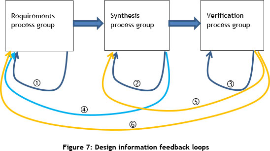
The first feedback loop exists within the requirements management process group, and occurs when establishing requirements. During the activity of formulating requirements, they are reviewed and updated to the point where all requirements relevant to a specific project have been validated. In this period, it is possible to change requirements statements (e.g., in a database) without undue constraints. Therefore, the mechanism used to record requirements should allow for changes during the requirements formulation cycle, but thereafter (i.e., after establishment of the requirements baseline) it must be possible to prevent unauthorised changes to requirements statements to protect the integrity of validated requirements.
The second loop shown in Figure 7 is the loop within the synthesis process group, which is inherent to the design and integration process. Feedback loops exist between the detailed design, design realisation, and integration process functions. Problems and errors are invariably detected during integration activities. These problems typically need corrective action in terms of a realised system element and the life cycle data associated with the element. This implies that control over life cycle data should have sufficient flexibility to allow changes to be made promptly, up to the establishment of the verification baseline.
The third loop, which exists in the verification process group, involves the development of verification cases and procedures. Integration testing must include dry runs of verification tests in order to remove errors from the subject under test as well as from test documentation. This will prevent undue rework during the formal verification stage. Draft issues of test documentation should be used to ensure all errors have been removed from test procedures prior to formal verification testing. This also serves as validation of test procedures. Note that this loop ceases to exist after establishment of the verification baseline.
The loops described up to this point can be regarded as 'normal' for an engineering process, and pose no challenges to the process design.
The fourth loop shown in Figure 7 occurs either when new requirements have been identified, or when errors are found in baselined requirements as a consequence of synthesis activities. In this instance, corrections to requirements require updates to the requirements baseline, which can only be performed by applying formal configuration change control.
The fifth and sixth loops shown in Figure 7 can be considered simultaneously. These loops occur when a problem has been detected during the verification process, necessitating updates to the verification baseline or the requirements baseline, or both. A primary objective of the formalisation of the development process is to prevent the occurrence of these loops, due to the impact of updating requirements and verification baselines - and because verification data collected up to the point of detection of the problem may be rendered invalid.
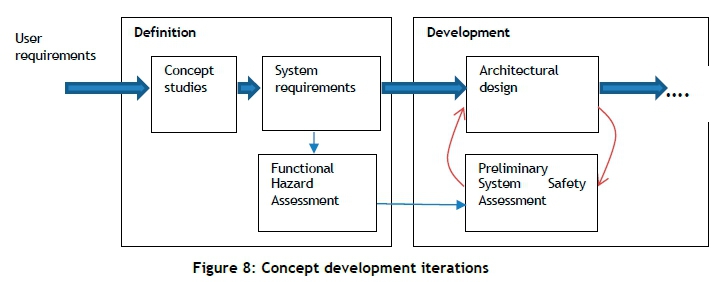
6.5 Concept development iterations
A situation of significance, where baselining of preceding process function outputs must be postponed until the completion of succeeding process functions, exists during the stage when the system concept is developed. It is important to recognise that agreements can only be finalised when: the system architecture (including interface protocols and redundancies) has been defined; the design assurance and software levels of the constituent CIs have been determined; and the extent of verification testing is known, as these are the most significant cost drivers. This implies that the product configuration data associated with process functions - i.e., requirements analysis, functional hazard assessment, architectural design, preliminary system safety assessment, and verification planning - can only be baselined after all the iterations within this loop have been completed. This approach is shown in Figure 8, and allows for a significant reduction in project risks in terms of cost estimation, as well as the containment of 'scope creep'.
The requirements should be baselined - i.e., protected against unauthorised changes - after the agreement has been finalised.
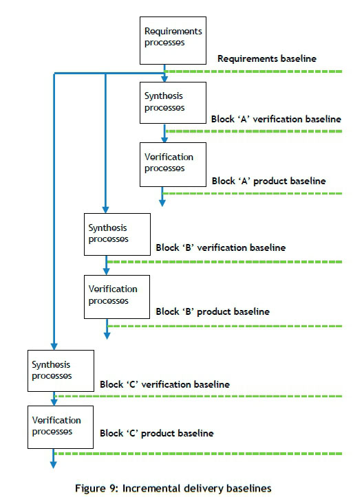
6.6 Incremental development of software functionality
An advantage of the methodology of incremental development of software functionality is that it reduces the amount of data to be validated and verified at a specific point in time. It also provides preliminary system functionality to support the development of other aspects of the aircraft during development at earlier stages in the programme than would have been possible with a single linear development strategy. It also represents contractual milestones that are readily quantifiable. Note that sets of requirements earmarked for development 'block' stages must be identified during the project planning phase. For each block, low level details (algorithms) for the set of software requirements to be implemented are developed, realised in source code, and integrated with the previous software build. The updated software is integrated in the target computer, and subjected to system level integration tests. When all integration problems related to the software build have been resolved, the applicable life cycle data is baselined, and the system hardware and software are subjected to verification tests.
The cycle is shown in Figure 9 for an example of three blocks.
7 VALIDATION OF THE LIFE CYCLE MODEL
The life cycle model presented in this paper for the development of airborne electronic equipment was validated and verified by employing a formal research process [21]. The life cycle model served as the basis for a comprehensive process design described in an engineering manual at Denel Aeronautics. It is evident that the correct method by which the process design can be validated is to apply the process to a development project and to evaluate the results. Validation of the process presented in this article was achieved by means of acceptance into the Denel Aeronautics Quality Management System (QMS) after rigorous validation by a team of experts.
The development process shown in Figure 9 is currently used as the basis for planning a major upgrade to the mission systems of the Rooivalk helicopter.
8 APPLICATION OF THE LIFE CYCLE MODEL TO OTHER DEVELOPMENT PROCESSES
The generalised life cycle model in Figure 4 was shown to support a simplified view of the essential activities that are required for the development of airborne electronic equipment, commensurate with the applicable recommended practices.
This simplified view was achieved by the logical grouping of engineering activities in the form of process functions that receive inputs from other process functions and produce outputs for use by downstream process functions, where controls and enablers are identified for each process function. The grouping of the activities in terms of requirements, synthesis, and verification tasks allowed for the definition of clear-cut baselines, simplifying the control of the process and the management of information feedback that occurs in the development process.
This notion of process functions, together with controls and enablers, as well as the control of baselines in terms of requirements, synthesised system, and verified system, provides a methodology by which the engineering of any type of system can be planned and managed effectively.
This methodology applies in particular to electronic system development processes where evidence is required that the integrity of the system is ensured, as it provides a simple but structured view of the implementation of the verification and validation tasks associated with such processes.
9 CONCLUSION
A simplified life cycle model for the development of airborne electronic systems was presented. This life cycle model provides a method for integrating all activities related to the efficient development and certification of electronic equipment required by airworthiness regulations. This method also provides a convenient way to plan and manage a development process for airborne electronic equipment. This life cycle model is not necessarily restricted to the domain for which it was developed, and can be applied to the engineering of systems in general, where confidence in the integrity of the system under development must formally be established.
REFERENCES
[1] Blanchard, Fabrycky: Systems engineering and analysis (fourth ed.)(2006). Prentice Hall. [ Links ]
[2] MIL-STD-490A. 4 June 1985. Military standard: Specification practices. AMSC NO. F3630. Department of Defence, Washington, D.C. [ Links ]
[3] MIL-STD-1521B (USAF). 4 June 1985. Military standard: Technical reviews and audits for systems, equipments, and computer software. AMSC NO. F3631. Department of Defence, Washington, D.C. [ Links ]
[4] MIL-STD-498. 5 December 1994. Military standard: Software development and documentation. AMSC NO. N7069. Department of Defence, Washington, D.C. [ Links ]
[5] RSA-MIL-STD-3. 1991. Standard for programme baselines. RMSS Document 5 (February 1991). [ Links ]
[6] International Standard ISO/IEC 15288:2008(E) / IEEE Std 15288™-2008 (Revision of IEEE Std 15288-2004). Systems and software engineering - System life cycle processes (second ed.). Software & Systems Engineering Standards Committee of the IEEE Computer Society. Published 31 January 2008. Printed in the United States of America. [ Links ]
[7] International Standard ISO/IEC 26702:2007(E) / IEEE Std 1220™-2005 Application and management of the systems engineering process. Software & Systems Engineering Standards Committee of the IEEE Computer Society. Published 9 September 2005. Printed in the United States of America. [ Links ]
[8] EIA Standard ANSI/EIA-632-1998. Processes for engineering a system. Approved: January 7,1999. Published by ELECTRONIC INDUSTRIES ALLIANCE 1998 Engineering Department 2500 Wilson Boulevard Arlington, VA 22201 [ Links ]
[9] International Standard ISO/IEC 12207 / IEEE Std 12207-2008. 1995. Information technology - software lifecycle processes (Second edition) Software & Systems Engineering Standards Committee of the IEEE Computer Society. Published 2008-02-01. Printed in the United States of America. [ Links ]
[10] RTCA/DO-178C. 2011. Software Considerations in Airborne Systems and Equipment Certification. Prepared by: SC-205 December 13, 2011 © 2011 RTCA, Inc. 1150 18th Street, NW, Suite 910, Washington, DC 20036-3816 USA. [ Links ]
[11] Aerospace Recommended Practise ARP4754 REV. A: (R). 1996/2010. Guidelines for development of civil aircraft and systems. Published by SAE International, 400 Commonwealth Drive, Warrendale, Pennsylvania, USA. [ Links ]
[12] RTCA/DO-254. 2000. Design assurance guidance for airborne electronic hardware. Prepared by: SC-180 April 19, 2000 © 2000 RTCA, Inc. 1150 18th Street, NW, Suite 910, Washington, DC 20036-3816 USA. [ Links ].
[13] SAE International Aerospace Recommended Practise ARP4761 . 1996. Guidelines and methods for conducting the safety assessment process on civil airborne systems and equipment. Published by SAE International, 400 Commonwealth Drive, Warrendale, Pennsylvania, USA. [ Links ]
[14] INCOSE Systems Engineering Handbook - A Guide for System Life Cycle Processes and Activities, version 3.2.1. January 2011. INCOSE-TP-2003-002-03.2.1. Prepared by: SE Handbook Working Group; International Council on Systems Engineering (INCOSE) 7670 Opportunity Rd, Suite 220 San Diego, CA 92111 -2222. [ Links ]
[15] BKCASE Editorial Board. 2015. The guide to the systems engineering body of knowledge (SEBoK), v. 1.4. R.D. Adcock (EIC). Hoboken, NJ: Trustees of the Stevens Institute of Technology. Accessed 16 March 2016. www.sebokwiki.org. BKCASE is managed and maintained by the Stevens Institute of Technology Systems Engineering Research Center, the International Council on Systems Engineering, and the Institute of Electrical and Electronics Engineers Computer Society. [ Links ]
[16] Beck, Kent et al. Manifesto for agile software development. (http://agilemanifesto.org/) Accessed 18 March 2016. [ Links ]
[17] Larman, C; and Basili, V.R. Iterative and incremental developments: A brief history. IEEE Computer, Volume: 36, Issue: 6,June 2003. ISSN: 0018-9162. [ Links ]
[18] Royce, Winston.Managing the development of large software systems. Proceedings of IEEE WESCON, 26 August 1970, pp. 1-9. [ Links ]
[19] Estefan, J.A. 2008. Survey of model-based systems engineering (MBSE) methodologies. Pasadena, California: Jet Propulsion Laboratory, California Institute of Technology. INCOSE MBSE Initiative. [ Links ]
[20] ADB062457. 1981. Integrated computer-aided manufacturing (ICAM) architecture, Part II, Volume IV - Function modelling manual (IDEF0). AFWAL-TR-81-4023, Materials Laboratory, Air Force Wright Aeronautical Laboratories, Air Force Systems Command, Wright-Patterson Air Force Base, Ohio 45433, June 1981. [ Links ]
[21] Viljoen, D.A. 2016. Synthesis and evaluation of engineering processes for the development of airborne electronic equipment. PhD thesis in Development and Management Engineering, North-West University. [ Links ]
* Corresponding author: daniev@denelaviation.co.za

