


Servicios Personalizados
Articulo
 Inglés (pdf)
 Articulo en XML
 Referencias del artículo
Indicadores

Links relacionados
-
 Citado por Google
 -
 Similares en Google
Compartir

 Permalink
South African Journal of Industrial Engineering
versión On-line ISSN 2224-7890
versión impresa ISSN 1012-277X
S. Afr. J. Ind. Eng. vol.27 no.2 Pretoria ago. 2016
http://dx.doi.org/10.7166/27-2-1327
CASE STUDIES
Development of an automated guided vehicle controller using a model-based systems engineering approach
T. Ferreira; I.A. Gorlach*
Department of Mechatronics Nelson Mandela Metropolitan University, South Africa
ABSTRACT
Automated guided vehicles (AGVs) are widely used for transporting materials in industry and commerce. In this research, an intelligent AGV-based material-handling system was developed using a modelbased systems engineering (MBSE) approach. The core of the AGV, the controller, was designed in the system modelling language environment using Visual Paradigm software, and then implemented in the hardware. As the result, the AGV's complex tasks of material handling, navigation, and communication were successfully accomplished and tested in the real industrial environment. The developed AGV is capable of towing trolleys with a weight of up to 200kg at walking speed. The AGV can be incorporated into an intelligent material-handling system with multiple autonomous vehicles and work stations, thus providing flexibility and reconfigurability for the whole manufacturing system. Ergonomic and safety aspects were also considered in the design of the AGV. A comprehensive safety system that is compliant with industrial standards was implemented.
OPSOMMING
Die nywerheid- en handelsbedryf gebruik dikwels outomatiese begeleide voertuie. 'n Outomatiese begeleide voertuig gebaseerde materiaalhanteringsisteem is ontwikkel deur 'n modelgebaseerde benadering. Die voertuig se beheerder is ontwikkel deur gebruik te maak van Visual Paradigm sagteware en is op die hardeware geïmplementeer. Die ingewikkelde materiaalhanteringstake wat na die voertuig gestuur is, wat onder meer die hantering, navigasie en kommunikasie insluit, is suksesvol uitgevoer en getoets in 'n werklike nywerheidsomgewing. Die onwikkelde outomatiese begeleide voertuig kan waentjies met 'n massa van 200kg teen stapspoed sleep. Die outomatiesbegeleide voertuig kan by 'n intelligente materiaalhanteringsisteem, wat uit verskeie outonome voertuie en werkstasies bestaan, geïntegreer word. Dit bied dus die vermoë om die hele vervaardigingstelsel te herkonfigureer of maklik aan te pas. Ergonomiese en veiligheidsaspekte is ook oorweeg vir die ontwerp van die voertuig. 'n Omvattende veiligheidstelsel wat aan die toepaslike industriestandaarde voldoen is geïmplementeer.
1 INTRODUCTION
The use of mobile robots in industrial applications is growing in popularity, with companies such as Toyota [1,2] investing heavily in incorporating autonomous vehicles into the production process. According to Davich [3], labour is the main cost associated with manual material handling, and effective material-handling solutions can reduce a plant's operating cost by 15 to 30 per cent. According to Stewart [4], the use of robotic rather than human workers has enabled the automotive industry to ensure that tasks are performed according to expectations. Robotic workers are superior to human workers in areas such as speed and accuracy [5]. Furthermore, human workers are limited to the number of hours they are allowed to work or the maximum loads they are allowed to handle or are capable of handling. Safety plays an important role in industry, and so this is a key factor to consider. One of the main advantages of robotic workers is that they eliminate the need for humans to perform tasks that are dangerous to their health or are located in hazardous environments [4]. Despite the major benefits of using robots, their costs are still significantly high, and their use is not feasible for some applications. The costs of commercial AGVs were reported in Yakut Ali et al. [5] and Floreano et al. [6]. According to Floreano et al. [6], smaller robots cost less than larger robots because they use smaller mechanical components and electronics, yet they perform comparably. With the growing demand for mobile robots and improved production efficiency, companies such as Savant Automation [7], Egemin Automation, Kiva Systems, and Seegrid have focused on delivering robots that can satisfy customer needs.
Material-handling systems play an increasingly important role in industrial environments, ensuring that materials are delivered to production in the shortest possible time. Traditional material-handling systems require an assembly worker to abandon the assembly station in order to retrieve parts. To improve on traditional material-handling systems, Toyota introduced the set part system (SPS) in its factories in Japan and China. An SPS eliminates the need for an assembly worker to leave the station, since components are delivered directly by material handlers.The aim of this research is to develop an intelligent material-handling system, based on an AGV, that is capable of performing efficient, intelligent, and autonomous material handling, using an SPS, for a motor car final assembly at General Motors South Africa (GMSAf).
A number of system-modelling languages are applied in industry. Unified modelling language (UML) is well-known, and is used mainly for the design of software of industrial controllers; whereas the system modelling language (SysML) is an extension of UML that can be used to model complete systems, including hardware. SysML was developed by the Object Management Group 4.1 [8]. Visual Paradigm software is a version of SysML, and is used as an MBSE tool in this research.
A number of examples of SysML applications for modelling control systems are reported in the literature [9,10,11]. SysML was used to model and develop a novel thermal-spray controller from concept to fully-functional industrial system [9]. According to Brecher [10], a major advantage of using SysML is the possibility of modelling complex systems with ease, as was demonstrated in the development of control logic for a robotic material-handling system. Dajsuren [11] demonstrated a number of applications of SysML in vehicle control development.
The developed system model of an intelligent material-handling system consists of three SysML submodels: AGV, intelligent controller, and guide path design. The AGV model contains information about the design and operation of the AGVs in the system. The intelligent controller model contains information about the intelligent control of multiple AGVs in a system. Intelligent control addresses issues such as vehicle dispatching - i.e., the assignment of work to each AGV - and conflict resolution. The guide path design model contains information about the requirements and design of the AGV guide path.
2 BACKGROUND
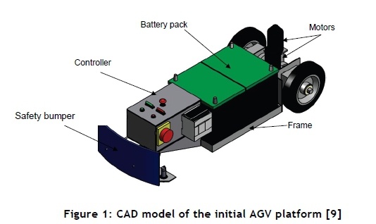
The initial mechanical design of the AGV, shown in Figure 1, was developed by Cawood [12]. The AGV design includes a welded frame, a differential drive, a motor controller, a Programmable Logic Controller (PLC), and a battery pack. For navigation of the AGV, the principle of a line following algorithm is used. The initial AGV design used an array of five induction sensors to detect the track laid out on the shop floor, providing a low-cost solution. However, the significant drift of the AGV during towing hampered performance. Thus, in the second design iteration, the induction sensors were replaced with a single magnetic sensor that provided stable movement for the AGV and better cornering at smaller turning radii. In addition to the safety bumper, a laser sensor was installed to improve the overall safety of the AGV.
3 DESCRIPTION OF THE SYSTEM MODEL
3.1 AGV Model
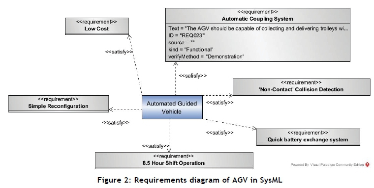
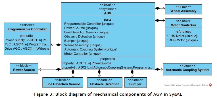
The first SysML diagram to be addressed is the requirements diagram for the AGV model. This diagram assigns a unique identifier to each requirement of the machine, providing traceability. This traceability is essential when working with complex systems, since it ensures that the requirements are satisfied for each machine and for the system as a whole. Figure 2 shows the AGV model requirements diagram with the requirements that need to be satisfied to achieve customer goals. By opening the central block of the model, the next diagram can be constructed - the AGV hardware structure block diagram (Figure 3). The diagram includes the main hardware components of the AGV: the programmable controller, power source, line detection sensor, obstacle detection mechanism, collision detection bumper, automatic coupling system, motor controller, and wheel assembly (including motors). Each of the mechanical components is modelled to a detailed level if required, as shown below on the automatic coupling system.
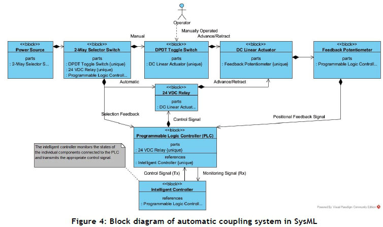
From the block diagram of the automatic coupling system (Figure 4), it can be seen that a selector switch is connected to the power supply of the AGV. The switch selection may be either automatic or manual. In manual mode, the operator is required to toggle a double pole double throw (DPDT) switch manually to control the motion of the linear actuator. In automatic mode, the actuator is controlled by a control signal from the PLC. Positional feedback of the actuator is obtained from the potentiometer output.
The next section will explain the model for the intelligent controller. The controller model focuses on the requirements of the controller and on the tasks the user should be capable of performing when using the controller.
3.2 Intelligent controller model
The intelligent controller is a dedicated central computer that obtains information from the various field devices and transmits appropriate control instructions. The intelligent controller model defines the requirements of the controller.
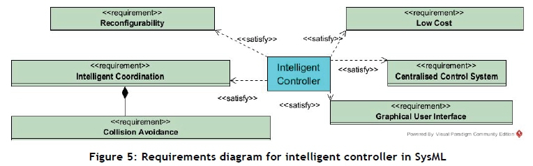
The requirements diagram (Figure 5) depicts the following requirements of the intelligent controller:
• Intelligent AGV coordination: The controller is required to coordinate multiple AGVs to ensure that no collisions occur while tasks are performed. The controller must dispatch AGVs so that the shortest possible cycle time is achieved.
• Flexibility: The controller is required to accommodate various possible working environments with a variable number of AGVs in the system.
• Centralised control system: The controller must be of the centralised type, which uses a central computer for AGV coordination.
• Low cost: The low implementation cost specified by the overall project requirement by GMSA must be achieved.
It can also be seen that collision avoidance is contained in the intelligent coordination requirement. This means that the intelligent controller should dispatch vehicles so that the risk of two or more vehicles colliding with one another is eliminated.
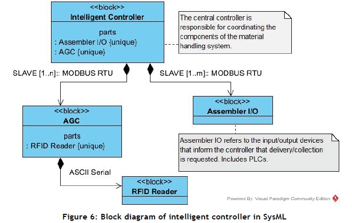
The structure of the intelligent controller model is represented in Figure 6, which shows that each AGV is equipped with a RFID scanner that provides information about the station or location of the AGV. The intelligent controller relies on operator input before dispatching a vehicle for SPS delivery or retrieval. The operator input can be a button, a proximity sensor, or a combination of the two.
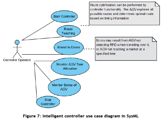
Now that the requirements and structure of the intelligent controller have been addressed, user interaction with the controller needs to be modelled. This is achieved with a use case diagram, which addresses the tasks that the user is required to perform, and is able to perform, on the controller. The use case diagram for the intelligent controller is shown in Figure 7. The user, with sufficient access, should be able to start and stop the controller. The controller may need to be stopped at the end of production or when maintenance is required. The main task of the controller operator will be route teaching.
The use case diagram for route teaching is shown in Figure 8. On the GUI, the user is able to configure RFID tags. This includes scanning a valid RFID tag and assigning a function to the scanned tag. For example, a scanned tag may be assigned a command to reduce the speed of the vehicle, or to branch left at the next split in the guide path.
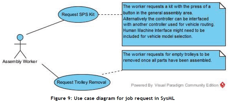
The operator is required to scan each of the RFID tags in order to determine the unique identifier. This information is then logged to the SQL server database for permanent record storage. With 240 possible read-only identifier combinations, it is essential that a simple assigning process is in place to ensure that a track can be created successfully in the shortest time. The major advantage of the chosen strategy is that RFID tags can be reconfigured even after being placed, thus allowing the route layout to be changed effortlessly without making physical changes to the track layout. When configuring RFID tags, a starting point or home position must be selected. The AGV should be placed such that the front of the bumper is in the centre of the RFID tag. Once the start button is pressed, the AGV will begin to move forwards until the first tag (i.e., the starting point) is reached - at which point an empty record is inserted into the database. As the AGV moves forwards it scans for RFID tags. The AGV will move continuously through the track until all configured RFID tags have been detected and timing information has been obtained between all tags. Once all tags have been configured, additional information is required for the controller to coordinate the AGV effectively; this includes a delivery request and a removal request signal. If the assembly worker does not request service, the AGVs will not necessarily perform the task (collection or delivery) in the shortest possible time. The request/removal signal may come from a proximity sensor, a pushbutton, or a digital signal from the controller of another station or process, as shown in the use case diagram job request (Figure 9).
The use of a dedicated central controller is essential to establishing coordination between the AGVs so that tasks are not duplicated (i.e., that only a single AGV responds to a request) and so that no collisions occur when multiple AGVs make use of the same track.
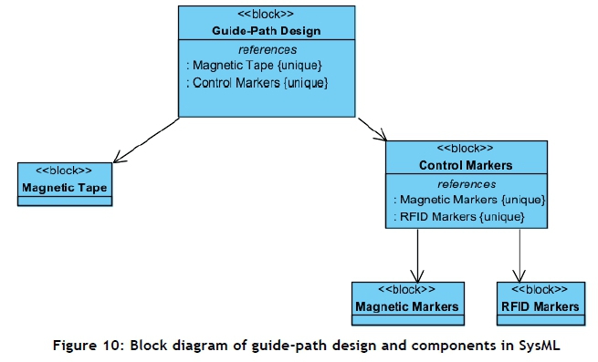
3.3 Guide-path design model
The guide-path design model is shown in Figure 10. The AGV path is constructed from magnetic tape because of its robustness and cost-effectiveness. In addition to the magnetic track, it is also important for control markers to be placed at various locations on the track. These markers provide information to the AGV about which action to take when passing them. They may be either magnetic markers (constructed from the same magnetic tape as the guide path) or RFID markers. The AGV path was modelled for two manual assembly stations and two AGVs in the service loop delivering different SPS kits to each of the assembly stations, as shown in Figure 11.
In a simple system, the AGVs will execute a service loop by first removing an empty trolley from station 'A' before removing an empty trolley from station 'B'. This needs to be done to avoid collisions, as no alternative routing is available. Similarly, a SPS kit should first be delivered to station 'A' and then to station 'B' (for the assumed direction of travel). As a result of the sequencing constraints, a delay may occur in the process. To overcome this delay it is necessary to provide alternative routes that the AGV may follow to avoid collisions.
An example of an alternative route would be to lay tape from point 'A' to point 'B'. This way the intelligent controller can evaluate the position of each AGV and advise whether an alternative route should be taken.
4 IMPLEMENTATION OF THE AGV CONTROLLER
The SysML model of the AGV was used to develop the intelligent AGV controller. The controller was implemented in Microsoft Visual Studio, since it allows for flexible programming and simple GUI creation. An interface was created for the AGV controller, with four main data tables, displayed on the main screen, that follow the SysML use case diagram (Figure 8). SQL Server 2012 was used to create the database that stores the obtained information, which can be accessed from the VB.Net application. Modbus communication is used to communicate between the Micrologix 1100 PLC and a host computer.
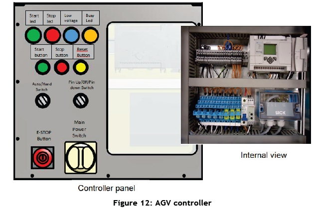
The SysML block diagram (Figure 6) of the controller was implemented in the AGV controller (Figure 12). The core of the controller is an Allen Bradley Micrologix 1100 PLC with 10 digital inputs, two analogue inputs, and six relay outputs. In addition to this, it allows for I/O expansion cards to be installed in the PLC, thus expanding its capabilities if required. Communication between the PLC and the motor controller is achieved with a MAX232 chip, which converts a serial signal from the PLC to the TTL level signal required by the Sabertooth motor controller.
Setting the AGV controller involved the following tasks: configuring the magnetic guide sensor, setting up the long range laser scanner for the safety system, configuring the RFID scanner, configuring the motor controller, and programming the PLC.
The laser scanner was configured using SOPAS software to meet the following requirements:
• Wide angle zone for detecting obstacles up to at least 3m, which is used for travelling along a long straight track at maximum speed without obstacles nearby.
• Loading zone for collecting a trolley. This zone has a narrow angle at short range to ensure that the trolley is not detected as an obstacle. A wide angle zone is be reactivated once the AGV is clear of the trolley to ensure that obstacles are detected effectively.
The most challenging task was to achieve reliable path-following motions using the magnetic guide sensor. This can be explained as follows. The analogue signal from the sensor is converted into an integer by the PLC, and then it is subtracted from an experimentally-determined value for when the magnetic tape is in the centre of the AGV. The obtained value represents the error signal. A scaling function was used to convert the error signal to a smaller range that is used by the PID function, which returns a decimal value that represents the required differential speed of each motor. This speed differential is added to one motor while being subtracted from the other, depending on the position of the centre the AGV relative to the guide tape. The PID tuning parameters were experimentally determined with the assistance of a SCADA program that was created in Movicon and was used to read the error signal and the motor command values from the PLC during runtime. The PID parameters were adjusted until the graph produced satisfactory results. The differential speed command of each motor was then converted from decimal to hexadecimal in the PLC programme. The Allen Bradley PLC was programmed in Ladder using RSLogix Micro software.
The RFID scanner, located at the bottom of the AGV, creates a magnetic field around the scanner. When a RFID tag is moved into the magnetic field, the induced current produces a unique identifier value that is interpreted by the RFID reader. Meaning can be assigned to RFID tags through the intelligent controller user interface. The following control instructions were developed:
• Node/branch selection: The AGV can follow either the left hand side or the right hand side track when reaching a fork in the road.
• Reduce speed: Slows down the AGV. This is important for areas where humans often operate.
• Increase speed: Increases the speed of the AGV. This is useful in areas where there are no obstacles.
• Stop the AGV: Stops the AGV until a new task is assigned.
• Safety zone selection: Used to select any one of the 16 available safety zones configured for the laser scanner.
• Work station: Defines a location from which a trolley will be collected, or to which it will be delivered.
• Charging station: Defines a location where an automatic charging station is located (optional).
• Activate tow pin: Used to advance the tow pin and engage with a SPS trolley.
• Starting point: Identifies a starting point or home position for the AGV.
When configuring RFID tags, the teaching run was based on the fact that all tag values are known; and it was assumed that they had been configured correctly. The controller logged the time between the sensing of each tag. This information is required when dispatching vehicles so that the shortest cycle time will be achieved. The time between tags is updated constantly during runtime, because - although a short time may be measured during the set up of the track - that particular section may experience heavy traffic during production hours that may affect the time it takes to reach its destination. This way the controller will learn the shortest route, based on past experience. When reading an RFID tag that is configured as a 'node', the AGV will first follow the LHS track at that node, and then the RHS track when it scans it again later in the teaching run. The AGV will continue to drive along the track until timing information has been obtained for all RFID tags in the system, along with links between the nodes. For example, for a simple track with a starting point, a node splits the path into two branches, each with a work station, which later join into a single track that leads back to the starting point. During a teaching run, the AGV scanned the starting point and moved until it reached the node from where it was supposed to follow the LHS path that led to the first work station. From there the AGV continued to drive until it reached the starting point again. The AGV continued to move until it reached the node again, at which time it was supposed to follow the RHS track until it reached the second work station. From there the AGV again moved forward until it reached the starting point for the second time. Once it had done so, the teaching run was complete, since the controller had obtained the required timing information for all the configured tags, and it also learned that a 'branch to the left' command is needed at the node if it is required to get to work station 1, and 'branch to the right' if it is required to get to work station 2.
A failure modes and effect analysis (FMEA) was carried out to identify the potential shortcomings of the AGV controller design. The failure modes associated with operational risks were considered as critical. For example, a failure of the laser scanner would result in a collision with an object. Although the safety bumper would deactivate the motors in such a case, the substantial inertia of the moving AGV with a loaded trolley could cause serious damage or injury. In order to avoid this scenario, the PLC programme was amended to interlock with an additional laser scanner output that reports the device's status at all times. All the aspects related to safety identified through the FMEA were accordingly reflected in the operational manual.
5 RESULTS
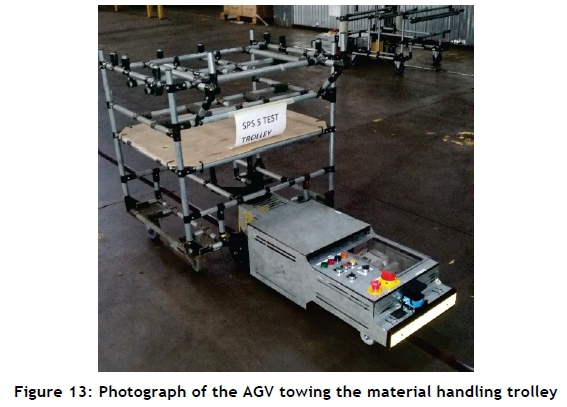
The performance of the AGV controller with respect to path following, power monitoring, and safety was evaluated in the experiments. A magnetic tape track was laid out according to the intended AGV path in the real working environment. The AGV was programmed to follow the path and to take turns according to the technological requirements. The AGV was proven to be capable of towing a load of 200kg. Figure 13 shows the developed AGV towing a trolley as part of the SPS for material handling. In the experiments, the two AGVs functioned satisfactorily when operating together in a service loop. Each AGV performed tasks based on its own internal sequence, which proved that the AGVs are capable of operation even in the absence of the intelligent controller. This is a major advantage, since it eliminates downtime when the intelligent controller is out of operation for maintenance.
In line with the design requirements, it is important for the AGV to stop operating whenever the supply voltage drops below a selected value. The AGV was operated and continuously monitored to determine the threshold voltage of the supply. Significant speed reduction was observed when the supply voltage dropped below 23V. A threshold voltage of 23.5V was selected on the voltage sensitivity relay (VSR) . Once the VSR has been set up, the AGV was operated until the blue indicator lamp came on to indicate that a low level of supply had been detected. The voltage was measured to be 23.5 ± 0.1V, which indicated correct monitoring. Once the measurement had been completed, the AGV was allowed to continue with its operation until it automatically stopped by the internal timer set by the PLC program. Once the PLC had stopped the AGV, it was unable to restart it until the batteries had been replaced. The final voltage on the PLC was measured to be 23.3 ± 0.1V.
The safety system includes a long-range laser scanner and a safety bumper. The laser scanner proved reliable in sensing an object, regardless of its material or reflectivity. Scenario-based testing was carried out to ensure that the safety of the AGV is satisfactory, and that it does not pose a threat to the operator under normal operation.
6 CONCLUSION
In this research, a controller for an intelligent AGV-based material-handling system was developed using Visual Paradigm software, an MBSE tool. The AGV controller is capable of:
• Autonomous retrieval and delivery of SPS trolleys
• Effective non-contact collision detection and avoidance
• Continuous operation for a duration of 16 hours before the need for battery charging
• Safe operation in the working environment
In addition to the above capabilities, the AGVs proved to be reliable when detecting control markers and responding to the input command received from them. When both marker sensors were active at the same time, the sequence in the PLC was incremented. This approach allowed for less magnetic tape to be used, and also increased the probability of a successful read.The improved line-sensing capabilities, along with the implementation of PID control, significantly improved the performance of the AGVs. The decrease in oscillation also resulted in more reliable marker detection and improved positioning when retrieving an SPS trolley.
The use of a laser scanner allowed for multiple safety zones to be configured, and thus for the AGVs to work safely in different working environments, regardless of the space constraint.
In the experiments, two AGVs were operated together, and independently performed the predetermined tasks in a service loop in the absence of a cell controller. However, a dedicated cell controller would allow for more efficient operation in applications where cycle time is critical.
The drawback of the current design is that the sequence of tasks is hard-coded into the PLC program of the AGV, making a dedicated cell controller necessary in order for a new sequence of tasks to be developed in a GUI and transferred to the PLC using the Modbus protocol.
The application of SysML in this research demonstrated that the MBSE approach can facilitate the sound functional design of complex controllers for industrial automation and systems.
REFERENCES
[1] Trebilcock, B. 2012. Modern materials handling. [Online] Available at: http://www.mmh.com/article/how_toyota_automated_the_delivery_of_parts_and_subassemblies [Accessed 2 April 2013]. [ Links ]
[2] Lean Mangement Instituut. 2006. Toyota's new material-handling system shows TPS flexibility. [Online] Available at: http://leaninstituut.nl/publications/1106/ToyotaNewMaterialHandlingSystem.pdf [Accessed 11 April 2013]. [ Links ] "
[3] Davich, T. 2010. Material handling solutions: A look into automated robotics. Thesis, University of Wisconsin-Madison, USA. [Online] Available at: http://tc.engr.wisc.edu/files/2013/02/Davich2010.pdf [Accessed 2 April 2013]. [ Links ]
[4] Stewart, T. 2009. A look at how the automobile industry uses robots. [Online] Available at: http://www.helium.com/items/1409985-robots-in-the-automobile-industry-robots-making-cars-robots-stealing-jobs_[Accessed 2 April 2013]. [ Links ]
[5] Yakut Ali, M., Hossain, S.G., Jamil, H. & Haq, M.Z. 2010. Development of automated guided vehicles for industrial logistics applications in developing countries using appropriate technology. International Journal of Mechanical & Mechatronis Engineering, 10(02), pp. 13-17. [ Links ]
[6] Floreano, D., Godjevac, J., Martinoli, A., Mondada, F. and Nicoud, J.-D. 1999. Advances in intelligent autonomous systems. In: S G. Tzafestas (ed.), Design, control, and applications of autonomous mobile robots. Dordrecht: Springer, pp. 159-186. [ Links ]
[7] Savant Automation. 2012. Savant automation. [Online] Available at: http://www.agvsystems.com [Accessed 2 April 2013]. [ Links ]
[8] Object Management Group Inc. OMG system modeling language. [Online]. Available at: http://www.omgsysml.org [Accessed 2 April 2013]. [ Links ]
[9] Barth, D., Gorlach, I.A. and Gruhler, G. 2010. Development of a novel controller for a HVAF thermal spray process, Proceedings of the International Conference on Competitive Manufacturing (Coma'10), Stellenbosch, South Africa. [ Links ]
[10] Brecher, C. Nittinger, J.A. and Karlberger, A. 2013. Model-based control of a handling system with SysML, Procedia Computer Science 16, pp. 197-205. [ Links ]
[11] Dajsuren, Y. 2014. Automotive system and software architecture. [Online] Available at: http://www.win.tue.nl/-aserebre/2IW80/2013-2014/AutomotiveArchitectures.pdf [Accessed 9 June 2016]. [ Links ]
[12] Cawood, G.J. 2013. Design of low-cost autonomous guided cart for material handling. Dissertation, Nelson Mandela Metropolitan University, Port Elizabeth, South Africa. [ Links ]
Submitted by authors 13 Aug 2015
Accepted for publication 13 Jun 2016
Available online 12 Aug 2016
* Corresponding author Igor.Gorlach@nmmu.ac.za

