


Services on Demand
Article
 English (pdf)
 Article in xml format
 Article references
Indicators

Related links
-
 Cited by Google
 -
 Similars in Google
Share

 Permalink
South African Journal of Industrial Engineering
On-line version ISSN 2224-7890
Print version ISSN 1012-277X
S. Afr. J. Ind. Eng. vol.27 n.2 Pretoria Aug. 2016
http://dx.doi.org/10.7166/27-2-1201
GENERAL ARTICLES
A round robin study for laser beam melting in a metal powder bed#
B. AhujaI, III, *; A. SchaubII; D. JunkerII; M. KargI, III; F. TennerI, III; R. PlettkeII; M. MerkleinII; M. SchmidtI, III
IInstitute of Photonic Technologies, Friedrich-Alexander-Universität Erlangen-Nürnberg, Germany
IIInstitute of Manufacturing Technologies, Friedrich-Alexander-Universität Erlangen-Nürnberg, Germany
IIIErlangen Graduate School in Advanced Optical Technologies (SAOT), Friedrich-Alexander Universität Erlangen-Nürnberg, Germany
ABSTRACT
With its ability to fabricate fully dense three-dimensional structures by selectively melting micro-sized metal powder, the additive manufacturing process of laser beam melting (LBM) is considered by many to be a significant technology that is complementary to the conventional forming and subtractive manufacturing processes. However, even with its ability to fabricate structures with characteristics comparable to conventional fabrication, the LBM process often lacks the consistency and degree of repeatability essential for its industrial acceptance for certain end-product applications. Inconsistency in the characteristics of structures is often related to a combination of variations in system technology, process, and user influence. In order to understand fully the potential and limitations of the LBM process, the paper discusses the design, methodology, and results of a round robin test conducted within the Collaborative Working Group (CWG) lasers in production at the International Academy of Production Engineering (CIRP). Observed mechanical characteristics for samples from each of the participants are presented. The experiments are designed to obtain data related to mechanical characteristics for different build orientations and processing conditions in addition to the inherent system technology variations. The paper further discusses the observed process phenomena and their association with the induced mechanical characteristics.
OPSOMMING
Die additiewe laserstraal smeltproses word deur kenners as 'n noemenswaardige tegnologie wat bydra tot die konvensionele vorming- en masjineringvervaardigingsprosesse geag, omdat dit oor die vermoë beskik om digte, driedimensionele strukture te vervaardig. Selfs met dié vermoë om strukture met eienskappe soortgelyk aan die konvensioneel vervaardigde strukture, ly die laserstraal smeltproses dikwels aan n tekort aan konsekwentheid en herhaalbaarheid wat krities is tot die industriële aanvaarding daarvan. Die veranderlikheid in die eienskappe van strukture is dikwels verwant aan 'n kombinasie van variasies in die sisteem tegnologie, proses- en gebruikerinvloed. Hierdie navorsing bespreek n rondomtalie toets wat op verskeie laserstraal smelters, wat by die Internasionale Akademie van Produksieingenieurs (CIRP) in gebruik is, uitgevoer is. Die toetse se mikpunt was om die potensiaal en beperkinge geassosieer met die laserstraal smeltproses beter te verstaan. Die waargeneemde meganiese eienskappe van monsters van elkeen van die monsters word voorgehou. Die eksperimente is ontwerp om data, wat verwant is aan die meganiese eienskappe wanneer verskeie veranderlikes tydens die vervaardigingsproses teenwoordig is, te verkry. Die waargeneemde prosesverskynsels en hul assosiasies met die geïnduseerde meganiese eienskappe, word dan bespreek.
1 INTRODUCTION
Laser beam melting (LBM) is classified as an additive manufacturing process that enables the fabrication of fully dense three-dimensonal metal structures. The raw material used is usually metal powder, and the binding is thermally induced by a high-intensity laser beam [1]. During the process, the laser beam selectively melts micro-sized metal powder using a layer-by-layer method to achieve fully dense three-dimensional structures [2]. Commercial trademarks synonymous with laser beam melting include Direct Metal Laser Sintering (DMLS®) by EOS GmbH [3], LaserCUSING® from Concept Laser GmbH [4], and Selective Laser Melting (SLM®) used by SLM Solutions Group AG and Realizer GmbH [5]. In the context of this paper, all the commercial trademark processes mentioned above are referred to as 'laser beam melting'.
The fundamental methodology of laser beam melting involves the use of a high-intensity solid state laser, generally a Nd:YAG or Ytterbium fibre laser, to melt micro-sized metal powder selectively, and consequently to achieve a fully dense three-dimensional structure by a consistent solidification of the melt. The fabricated geometry is processed in the characteristic layer-by-layer methodology consistent with a typical additive manufacturing process [1]. Digital data provided to the machine system is in the form of sliced data as a representation of the complete structure of the computer-aided design [6]. The movement and focusing of the incident laser is achieved with a combination of focusing optics and scanner systems [7]. Although the fundamental methodology described above is the same for all laser beam melting systems, there are significant differences between the design and setup of each machine system. Some of the most significant variations can be found in the build size, recoating mechanism, optical design, and inert gas circulation. A key difference between the functioning of each commercial machine system is also its software interface and variations in scanning strategies. In addition to the inherent variations in system technology, the fabrication process is also highly user-dependent. Fabrication with laser beam melting requires a support structure to connect the base plate and the fabricated part [8]. The support structure is essential in controlling the deformation of parts caused by heat-induced stresses [9]. The design of the support structure is thus critical for the success of the fabricated structures [10]. Therefore, in addition to the system technology, user experience and understanding of the process play a crucial role in the success of a build [11].
A standardised test artefact focusing on the dimensional characterisation of additive manufacturing processes has been proposed by the National Institute of Standards and Technology (NIST) [12]. A separate benchmark study compared additive manufacturing processes with different binding mechanisms and materials. The processes compared were laser beam and powder bed-based, and worked on liquid phase sintering, full melting, and partial melting binding mechanisms [13]. Another benchmark study conducted in the field of laser beam melting is VDI 3405 Part 2.1 on AlSi10Mg [14]. The VDI inter-laboratory test is focused on creating a datasheet to inform the user of the expected tensile properties. They do not focus on aspects of process parameter development or phenomena for the observed variations. The round robin initiative presented here intends to compare the variations in the mechanical characteristics of the samples fabricated by different users of the laser beam melting process. In addition to the machine operator, the machine systems vary in their make and design. A key demand from industrial users of laser beam melting has been the development of new materials for the process [15]. The CIRP round robin test is therefore also designed to determine the ability of users to develop LBM process parameters.
2 PARTICIPANTS AND CORRESPONDING LBM MACHINE SYSTEMS
Participants in the round robin study presented here were members of the collaborative working group 'Lasers in Production' at the International Academy of Production Engineering (CIRP). In total, six institutes with LBM system technologies from Realizer GmbH, SLM Solutions GmbH, EOS GmbH, and Concept Laser GmbH participated in the study. The participating members were the Bremen Institute for Applied Beam Technology (BIAS) from Bremen in Germany, National Institute of Standards and Technology (NIST) from Gaithersburg, Maryland in the USA, Institute of Photonic Technologies (LPT) from Erlangen in Germany, Stellenbosch University (SU) from Stellenbosch in South Africa, Catholic University of Leuven (KUL) from Leuven in Belgium, and Industrial Technology Research Institute (ITRI) from Hsinchu City in Taiwan. In order to ensure anonymity, each participant was provided with an identifying letter from A to F. (The sequence of the letters does not correspond to the sequence in which the participants have been mentioned above.)
All participants within the round robin study were from an additive manufacturing research background and were considered experts in the field of laser beam melting. The participants had significant experience in the development of LBM process parameters for new materials. This consideration was kept in mind during the selection of participants, as the round robin study also required the development of process parameters for the selected material.
3 MATERIAL: STAINLESS STEEL 1.4540
The material used for all the experiments within the scope of this inter-laboratory test was stainless steel 1.4540. It is also classified by SAE grade as 15-5PH and as S15500 by Unified Numbering System (UNS). In addition to iron, the main constituents of the alloy included chromium 14 - 14.6 per cent, nickle 3.8 - 4.5 per cent, and copper 3.5 - 4.0 per cent [16]. A steel alloy is considered stainless steel if it contains at least 10.5 per cent of chromium [17]. The primary advantage of a stainless steel alloy is that it does not readily corrode, rust, or stain when in contact with water.
For LBM, the process parameters of 1.4540 are only provided by selected machine suppliers. The round robin study therefore also focused on assessing the ability of LBM machine users in developing process parameters for a new material. It is understood that most of the participants had access to the parameters of a similar stainless steel alloy 1.4404, which is a more common alloy used in the additive manufacturing industry. Although both are classified as stainless steel, there is a significant difference in the chemical constitution of the two materials - primarily in their chromium, nickel, and copper content. The variation is also observed in their physical properties, such as thermal conductivity, coefficient of thermal expansion, and specific heat capacity. These properties are expected to have an effect during the laser beam melting process, and thus the process parameters of the two materials are expected to differ.
The alloy 1.4540 is a precipitation hardening martensitic stainless steel or maraging steel. Although it has good weldability, a subsequent age hardening of the material is required to attain better mechanical properties. An age hardening heat treatment induces precipitation of intermetallic phases, which results in the enhanced strength of the alloy [16].
4 DESIGN OF THE ROUND ROBIN TEST
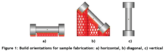
The aim of the CIRP laser beam melting round robin test was to initiate an extensive and detailed comparison of LBM machine systems, operator proficiency, process conditions, and their influence on the mechanical properties of laser beam melted parts. The round robin test was initiated to determine the tensile characteristics of samples fabricated from stainless steel 1.4540. The material was in the form of micro-sized powder. Participants were advised to source the material independently, based on the particle size most suitable for their machine system. Process parameters for the specific machine system are either provided by the system technology provider or developed by the individual participant. The process parameters for 1.4540 are only provided by EOS GmbH; and so other participants were expected to perform the development individually. In addition to the variations mentioned above, the test was also designed to understand the influence of orientation, build position, post-build surface machining, and post-build heat treatment on the observed mechanical characteristics. Thus the tensile test samples were fabricated with vertical, horizontal, and diagonal build orientations, as illustrated in Figure 1.
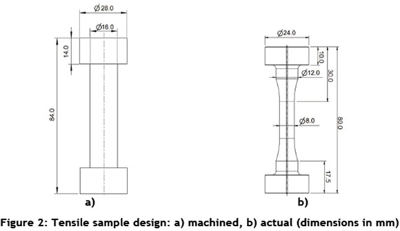
The samples selected for the round robin study had two design variants corresponding to machined and actual geometry. The machined samples would be exposed to a subtractive machining process to achieve a final design identical to the actual samples. The machining variation was introduced in order to determine the effect of surface roughness on the tensile characteristics of the samples. It was understood that a high surface roughness would have a negative effect on the tensile characteristics by potentially causing crack initiation during the application of tensile force. The design for the actual and machined samples is illustrated in Figure 2.
Apart from the build orientation and surface machining, a post-build heat treatment was performed on selected samples in accordance with the designated H900 heat treatment [18]. This involves annealing at about 480°C (900°F), followed by air cooling [19]. The post-build heat treatment was expected to result in increased ultimate tensile and yield strength, but a reduced elongation at break, as reported in previous studies done on the material [20]. Each participant was supplied with an identical build layout of the experiment. Support design and process parameters were developed independently by each participant.
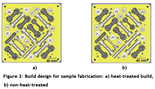
All the parts were aligned at a 45° angle to the recoating direction in order to minimise the area of contact between the edge of the part and the re-coater blade. Each sample was engraved with a unique identification number in the design, which would be reproduced in the actual part for identification. Figure 3 below illustrates the design of the two builds that each participant was required to fabricate.
Tensile tests were carried out in accordance with DIN 6892-1. In addition, an ARAMIS contactless optical measurement system was used to record and analyse the three-dimensional displacements of a stochastic black and white pattern painted onto the tensile specimen. A tensile test was carried out to determine yield strength, ultimate tensile strength, uniform elongation, and elongation at break for each sample.
5 ROUND ROBIN TEST RESULTS: TENSILE CHARACTERISTICS
This section focuses on the observed tensile characteristics from the samples fabricated in the round robin study. The tensile tests were carried out with a Walter + Bai FS-300 universal testing machine. The maximum test force was 300 kN. The tensile sample was positively fixated by two identical tools, one at each end. After the sample had been inserted and the test had begun, the machine built up an initial force of 100 N, which equalled a tension of about 5 MPa. All the samples were tested until rupture. Yield strength (Rp0.2), ultimate tensile strength (Rm), and elongation at break (Ag) were used as parameters to quantify the tensile characteristics of the samples. Figure 4 shows the analysis of the measured stress-strain diagrams, with the parameters for comparing the quality of the parts of each participant. There was a large difference between the measurements of each participant. Further discussion will follow, using all the measurements of each set of specimens.
For each participant, the final quantity of the tested sample varied. This was primarily due to the build failures experienced during the manufacture of the samples, which resulted in the supply of a reduced number of samples. And in some cases, the samples were deformed to such a degree that the tensile testing of these samples was not possible (Figure 5 b). Figure 5 a) illustrates a complete build with support structures individually designed by the participant.
The tensile characteristics of conventionally-processed and additively-manufactured 1.4540 were used as reference values. The yield strength, ultimate tensile strength, and elongation at break for conventionally-processed 1.4540 are 958 MPa, 1014 MPa, and 15 per cent respectively [16]. These values are taken from the online material property database MatWeb.com for the material processed in a heat-treated condition. For mechanical characteristics from the additively-manufactured process, the characteristics published by EOS GmbH were used. These published properties were from the samples obtained from the machine system EOS M 290. The yield strength, ultimate tensile strength, and elongation at break for additively manufactured 1.4540 on EOS M 290 were 1250 MPa, 1350 MPa, and 10 per cent respectively [20]. These values were obtained after a post-build heat treatment had been applied to the fabricated samples, as stated in the published datasheet.
5.1 Variation with post-build heat treatment
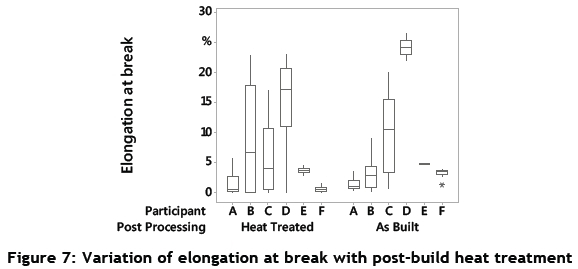
This section aims to determine the effect of post-build heat treatment on the yield strength, ultimate tensile strength, and elongation at break for the samples fabricated by the different participants. The participants were classified from A - F. Figures 6 and 7 illustrate the yield strength, ultimate tensile strength, and elongation at break respectively. The results in this section are shown in so-called 'box plots'. Within these diagrams, a vertical line represents the range between the maximum and minimum values. The box within this range presents the sector where 50 per cent of the results are contained. A horizontal line within the boxes symbolises the median. Statistical outliers are represented by asterisks. The effects discussed in the next section do not segregate the samples according to their build orientation or surface properties.
The post-build heat treatment was expected to increase the yield strength and ultimate tensile strength of the fabricated samples. This was due to the precipitation hardening mechanism for 1.4540, which was expected to be initiated during the solution annealing that the material underwent. The proposed heat treatment also enabled a stress reduction in the fabricated samples. Due to high heating and cooling rates resulting from extremely fast scan speeds and a high intensity laser beam, a typical laser beam melting process induced a high number of heat-induced stresses in the fabricated samples.
From Figure 6 it is evident that, in most cases, post-build heat treatment enabled an increase in yield strength. This was clearly evident for participants C, D, E, and F. For participant A, it was observed that the median value of the yield strength for the heat-treated samples was slightly higher than the median value for the samples without a post-build heat treatment. This was, however, not a clear indication of the increase, as the variation between the observed values of the yield strength for heat-treated samples from participant A was extremely high. The same degree of variation was not observed, however, in the samples without heat treatment for the same participant. As the heat-treated and standard samples were on separate builds, this effect could possibly have been a build-specific effect causing an inconsistency within the internal structure of the sample. Alternatively, it was considered whether any issues during the heat treatment could have resulted in the observed variation. This was, however, not determined to be the case by the participant. For participant B, it was also observed that the variation in the heat-treated build was higher than for the standard build. This variation was, however, lower than was observed for participant A. The median value for the heat-treated samples for participant B was also significantly higher than that for the non-heat-treated samples. As the heat treatment was performed by individual participants before the removal of the support, it is possible that there were variations between the heat treatment process from different participants, depending on the equipment and temperature-time profile used for the heat treatment process.
As was seen for the yield strength, a similar trend was observed for the ultimate tensile strength in Figure 6. An observed exception occurred with participant F, where the ultimate tensile strength was observed to be significantly lower for the non-heat-treated condition specifically, in comparison with participants D and E. Samples from participants A and B also indicated a higher variation for the ultimate tensile strength, similar to the observation for the yield strength. It was also observed overall that there was a higher number of samples with exceptional values for ultimate tensile strength. For participants C and D specifically, there were cases where the ultimate tensile strength for heat-treated samples was exceptionally low. This could be accounted for by the fact that the samples fractured before an elongation of 0.2 per cent, and therefore the samples were not considered as part of the yield strength observation.
According to established understanding, the initiation of precipitation hardening in 1.4540 should result in increased strength and reduced ductility [20]. This is also expected to be the case for Laser Beam Melted 1.4540, as indicated in the datasheet published by EOS GmbH [20]. The effect of precipitation hardening on ductility was most clearly observed for participants D and F. Although the elongation at break for participant F was significantly lower than that for participant D, in both cases a reduction of ductility could be observed with a post-build heat treatment. For other participants, the variation in the observed values of elongation at break was consistently high. It was difficult, therefore, to determine the exact effect of heat treatment on the elongation at break for these participants.
Although it is argued that the post-build heat treatment should initiate the precipitation hardening mechanism, resulting in reduced ductility, the fundamental laser beam melting process that involves selective powder melting in a layer-by-layer fashion should be considered. It could be argued that heat treatment already takes place during the LBM process - during the melting of the powder layer and the processing of consecutive layers -as they cause a reheating and cooling of the previously-formed layers. The degree of ductility reduction could therefore be dependent on the process parameters and processing conditions, such as platform heating, effective scan speed, and laser intensity. The design of the support structures is also expected to play a role in the thermal management of fabricated structures.
5.2 Variation with surface machining
This section describes the observed tensile characteristics classified according to the induced surface finishing of the fabricated structures. The conditions of the as-built samples only involved removal of the support structure, whereas for the machined samples, subtractive turning was applied to achieve a surface that resulted in a significant reduction of surface roughness in comparison with the non-machined samples.
Considering the variations observed for the yield strength, as indicated in Figure 8, no significant influence of surface machining on yield strength was evident. However, the comparative yield strength between the participants indicated a similar trend to that observed in Figure 6, with participants E and F generally outperforming the other participants. In comparison, a yield strength of 1250 MPa has been published for samples processed using LBM, and 958 MPa for conventionally-processed samples [16]. From Figure 8, it is also observed that for participants A, C, D, and F, the machined surface resulted in a higher ultimate tensile strength in comparison with the standard surface after the LBM process. This observation was not entirely evident for participants B and E. This could possibly have been due to variations in surface roughness for the different participants, depending on the layer thickness and particle size distribution. In comparison, an ultimate tensile strength of 1380 MPa has been published for samples processed using LBM, and 1014 MPa for conventionally-processed samples [20].
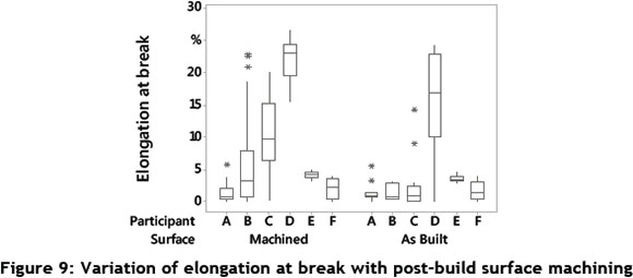
Based on the median values indicated by the bars on the box plots in Figure 9, it can be stated that, for all participants except A, an increase of elongation at break was evident. The high variations in the observed values were also due to the fact that the samples classified as machined and as built contained samples with and without post-build heat treatment.
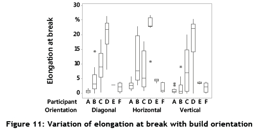
5.3 Variation with build orientation
This section aims to highlight the variation of tensile characteristics with build orientation. Samples were fabricated in horizontal, vertical, and diagonal build orientations to the base, as shown in Figure 1. The variation in build orientation aimed to analyse the possible effect of anisotropy on the tensile characteristics of the samples fabricated using laser beam melting. Due to the inherent layer-by-layer fabrication methodology, it has been found that the build orientation can have an effect on the mechanical characteristics of the fabricated samples [21].
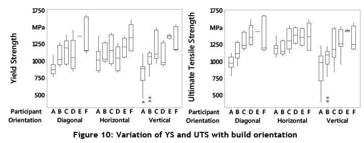
The comparison of the horizontal and vertical build orientation in Figure 10 indicates that, for participants A, C, D, and F, the horizontal build orientation had a slightly higher median for the yield strength in comparison with the vertical orientation. This might indicate a slight anisotropic behaviour of the fabricated samples. It is expected that the analysis of the ultimate tensile strength might reveal further indications of anisotropic behaviour. Analyses of the ultimate tensile strength with respect to build orientation indicated a stronger trend of anisotropy. Apart from participant E, the median values for ultimate tensile strength in the horizontal build orientation were higher than those observed in the vertical build orientation. This could be attributed to the relationship between the direction of tensile force and the layer orientation. In the case of the vertical samples, tensile force was applied perpendicular to the layer orientation, and thus the probability of fracture between the layers was significantly higher.
Elongation at break (Figure 11) indicated a high degree of variation between all participants. The best results were observed for participant D. The horizontal build orientation also indicated a more consistent result in comparison with the diagonal and vertical build orientations. In comparison, participant C indicated an overall higher degree of variation in all three build orientations. The high degree of variation in the elongation at break could also be attributed to the fact that the results in Figure 11 contained a combination of both heat-treated and non-heat-treated samples.
6 DISCUSSION: PROCESS PHENOMENA INFLUENCING MECHANICAL CHARACTERISTICS
This section presents some of the process phenomena that can be contributed to the observed variations of the mechanical characteristics presented in Section 4. In order to achieve good mechanical characteristics, it is essential that the fabricated structures have a high relative density and a consistent microstructure [8]. The structures should be free from porosity, as pores reduce the effective cross-sectional area of the structure and might also act as points of fracture initiation, especially in the case of tensile force application [11]. It is expected that an understanding and control of these phenomena could enable us to achieve better system technology and process conditions.
6.1 Relative density variation with process parameters
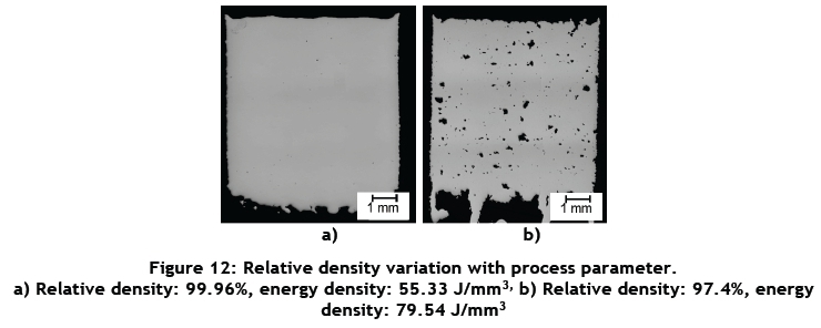
Laser beam melting process parameters play a primary role in determining the energy deposition during irradiation of the powder layer [22]. An ideal process parameter set aims to provide sufficient energy for complete melting of the metal powder and its fusion to the previously irradiated layer. An insufficient amount of energy can therefore lead to un-melted regions in the internal structure. By contrast, an excessive amount of energy can cause vaporisation of the material constituents with a low boiling point, leading to porosity due to vapour entrapment. The amount of energy is typically quantified using the parameter 'energy density', which is a combination of laser power, scan speed, layer thickness, and hatch distance. Parameters such as beam intensity and particle size distribution also play a critical role in determining the structural porosity of the specimens.
Figure 12 illustrates the effect of varying energy density on the structural porosity of the specimens for stainless steel 1.4540, processed using laser beam melting. The layer thickness and particle size distribution were kept constant for both specimens.
Fracture analyses of some tensile tested specimens revealed evidence of high porosity at the fracture zone. This is illustrated in Figure 13 a), for a specimen fabricated in vertical build orientation from participant B. The corresponding ultimate tensile strength for the illustrated specimen was found to be 973 MPa, which was one of the lowest values for participant B. In comparison, Figure 13 b) illustrates a specimen fabricated in the horizontal build orientation from participant E. The fracture zone indicates a ductile fracture and evidence of homogeneous melting at the fracture zone, consistent with the fabrication of structures with a high relative density. The corresponding ultimate tensile strength for the illustrated specimen was found to be 1242 MPa. Both the specimens were machined in the non-heat-treated condition.
6.2 Effect of build position on relative density
Without the use of specially-designed optics, the focus would be on a spherical surface causing varying beam intensity on the build platform, resulting in structural inconsistencies such as porosity. Specialised optical elements are therefore used to counter the focus shift of the laser beam during the irradiation on the build platform [23]. In the case of laser beam melting machine systems, this is achieved either by the combination of a galvanometer scanner and F-theta lens, or by the use of a dynamic focusing module (DFM) [24], also known as a 3D scanner, as illustrated in Figure 14.
A good optical design would enable consistency of beam intensity throughout the build plane. The optical design of each machine system varies, and is one of the major factors for variation in the quality of the fabricated parts.
Other factors such as quality of optics, design of the ventilation system, and inconsistency of build platform heating also contribute to the variation in the quality of fabricated parts. In order to understand the degree of inconsistency, the variation in structural porosity was determined for one of the LBM machine systems used in the round robin study. The observations indicated that a lower relative density was achieved in the outermost sections of the build platform. It was also observed that a higher relative density was achieved in the structures towards the centre of the build platform. Figure 15 illustrates the variation of relative density with respect to position on the build platform.
The flow and intensity of the gas stream could also have a varying effect on the quality of the fabricated structures. Spatter formation and the possible interaction of the laser beam with fume cloud could have a negative effect on the part quality. Based on the direction of airflow, this phenomenon would affect a certain region of the build. An effective gas stream also prevents the formation of dirt on the laser glass in the build chamber.
6.3 Variation with build duration
The melting of metal powder by irradiation of the laser beam causes the formation of fume and spatter during the process. In order to minimise the effect of these formations on the result of the build, it is essential to have an effective gas flow in the build chamber. In some cases, it is observed that the effectiveness of gas flow reduces with a long build duration. This can result in two phenomena, the potential fume-residue deposition on the laser glass, and ineffective spatter removal during irradiation of the metal powder. Deposition of residue on the laser glass would cause a reduction in the effective intensity incident on the build platform, possibly resulting in inadequate energy deposition during irradiation of the powder. On the other hand, contamination of the powder bed with spatter could result in unwanted impurities in the fabricated structure.
In addition to the above-mentioned phenomena related to system technology, material quality and user ability also play an important role in enabling a consistent and repeatable quality from the structures fabricated with laser beam melting in a powder bed.
7 CONCLUSION
The present research shows the design, execution, and results of a round robin test aimed at understanding the variations in mechanical characteristics due to varying processing conditions and system technology for laser beam melting in a powder bed. The processed material, stainless steel 1.4540, was selected for its high strength characteristics enhanced through the precipitation hardening mechanism. The designed round robin test also aimed to determine the user's ability in process parameter development for the laser beam melting process. The results presented here indicate a high degree of variation in the mechanical characteristics from different participants and, in certain cases, within the results achieved from the same participant. The effect of designed variations such as post-build heat treatment, surface alteration, and build orientation is also indicated in the results.
The study also elaborates on the possible phenomena affecting the resulting mechanical characteristics of the fabricated samples. Discussions in the paper focus on process and system technology-related issues such as process parameters, optical design, and gas stream flow. The effects of these issues on phenomena such as variation of structural porosity with build position and build duration are also discussed. It is expected that the scientific outcome of the performed research will result in developments that achieve a higher consistency and quality of products in laser beam melting.
ACKNOWLEDGEMENT
The authors of this paper acknowledge the work done by Maximilian Boulter as part of his Masters thesis at the Institute of Photonic Technologies, Friedrich-Alexander-Universität Erlangen-Nürnberg. The authors also acknowledge the financial support provided by DFG, the German Research Foundation under the collaborative research centre, SFB 814: Sub project B5. The authors gratefully acknowledge funding from the Erlangen Graduate School in Advanced Optical Technologies (SAOT) by the German Research Foundation (DFG) in the framework of the German excellence initiative.
REFERENCES
[1] VDI. 2014. VDI 3405: Additive Manufacturing Processes: Basics, definitions, processes. Association of German Engineers. Berlin: Beuth Verlag GmbH. [ Links ]
[2] Simchi, A. 2006. Direct laser sintering of metal powders: Mechanism kinetics and microstructural features. Materials Science and Engineering, 428 (1), pp. 148-158. [ Links ]
[3] EOS GmbH. N.d. DMLS; Additive Manufacturing technology. Website accessed on 25 May 2016; http://www.eos.info/additive_manufacturing/for_technology_interested. [ Links ]
[4] Concept Laser GmbH. N.d. LaserCUSING® - Laser melting with metals. Website accessed on 25 May 2016; http://www.concept-laser.de/en/technology/lasercusingr.html. [ Links ]
[5] SLM Solutions Group AG. N.d. SLM® 280 HL. Website accessed on 25 May 2016; http://www.stage.slmsolutions.com/index.php?slm-280_en. [ Links ]
[6] Ahuja, B., Karg, M. & Schmidt, M. 2015. Additive manufacturing in production - Challenges and opportunities, Proceedings of SPIE, Vol. 9353 935304-1. [ Links ]
[7] Das, S. 2003. Physical aspects of process control in selective laser sintering of metals, Advanced Engineering materials, pp. 701-711. [ Links ]
[8] Su, X., Yang, Y., Wang, D. & Chen, Y. 2013. Digital assembly and direct fabrication of mechanism based on selective laser melting. Rapid Prototyping Journal, 19, pp. 166-172. [ Links ]
[9] Zeng, K., Pal, D., Teng, C. & Stucker, B.E. 2015. Evaluations of effective thermal conductivity of support structures in selective laser melting. Additive Manufacturing Journal, 6, pp. 67-73. [ Links ]
[10] Zhang, B., Dembinski, L. & Coddet, C. 2013. The study of the laser parameters and environment variables effect on mechanical properties of high compact parts elaborated by selective laser melting 316L powder. Materials Science and Engineering, p. 584. [ Links ]
[11] Dadbakhsh, S., Hao, L. & Sewell, N. 2012. Effect of selective laser melting layout on the quality of stainless steel parts. Rapid Prototyping Journal, 18, pp. 241-249. [ Links ]
[12] Moylan, S., Slotwinshi, J., Cooke, A., Jurrens, K. & Donmez, M.A. 2012. Proposal for a standardized test artifact for Additive Manufacturing machines and processes, Solid Freeform Fabrication proceedings, Austin, Texas. [ Links ]
[13] Kruth, J.-P., Vandenbroucke, B., Vaerenbergh, J.V. & Mercelis, P. 2005. Benchmarking of different SLS/SLM processes as rapid manufacturing techniques, Int. Conf. Polymers & Moulds Innovations (PMI), Gent, Belgium. [ Links ]
[14] VDI 2014. VDI 3405, Part 2: Beam melting of metallic parts: Qualification, quality assurance and post processing. VDI, Association of German Engineers. Berlin : Beuth Verlag GmbH. [ Links ]
[15] Wholers Report. 2014. 3D printing and Additive Manufacturing: State of the Industry, Wholers Associates. Annual Worldwide Progress Report. [ Links ]
[16] MatWeb, LLC. N.d. AISI Type S15500 (15Cr-5Ni) Precipitation Hardening Stainless Steel tested at 205°C (400°F), condition H1025. [ Links ]
[17] British Stainless Steel Association. N.d. The basics about stainless steel. Accessed online on 25 May 2016; http://www.bssa.org.uk/about_stainless_steel.php. [ Links ]
[18] Fulcher, N.T. 1995. Stainless steel mill products. Office of Industries, U.S. International Trade Commission, Washington DC, p. 11. [ Links ]
[19] Kutz, M. 2002. Handbook of materials selection. New York: J. Wiley. [ Links ]
[20] EOS GmbH - Electro Optical Systems GmbH. N.d. Data sheet for EOS StainlessSteel PH1 for EOS M 290. Accessed online on 25 May 2016. https://scrivito-public-cdn.s3-eu-west-1.amazonaws.com/eos/public/2c79c109ca82d0e7/e83c11448f46b61ce51d2e0ae72d12ee/EOSjmaterial-datasheet_Stainless-Steel-PH1_M290_en.pdf. [ Links ]
[21] Simonelli, M., Tse, Y.Y. & Tuck, C. 2014. Effect of the build orientation on the mechanical properties and fracture modes of SLM Ti-6Al-4V. Material Science and Engineering, 616, pp. 1-11. [ Links ]
[22] Hanzl, P., Zetek, M., Baksa, T. & Kroupa, T. 2014. The influence of processing parameters on the mechanical properties of SLM Parts. 25th DAAAM International Symposium on Intelligent Manufacturing and Automation. Vienna, Austria. [ Links ]
[23] SCANLAB AG. N.d. Additive manufacturing (3D printing). Accessed online on 25 May 2016. http://www.scanlab.de/en/applications/additive-manufacturing. [ Links ]
[24] Coskun, M. 2014. Scanners: Three-axis laser scanning technology improves demanding materials processing applications. Laser Focused World. Accessed online on 25 May 2016. http://www.laserfocusworld.com/articles/print/volume-50/issue-02/features/scanners-three-axis-laser-scanning-technology-improves-demanding-materials-processing-applications.html. [ Links ]
Submitted by authors 17 Mar 2015
Accepted for publication 7 Jun 2016
Available online 12 Aug 2016
# This article is an extension of a paper presented at the 15Annual International RAPDASA conference held in Stellenbosch, South Africa in November 2014.
* Corresponding author bhrigu.ahuja@lpt.uni-erlangen.de

