


Services on Demand
Article
 English (pdf)
 Article in xml format
 Article references
Indicators

Related links
-
 Cited by Google
 -
 Similars in Google
Share

 Permalink
South African Journal of Industrial Engineering
On-line version ISSN 2224-7890
Print version ISSN 1012-277X
S. Afr. J. Ind. Eng. vol.26 n.3 Pretoria Nov. 2015
http://dx.doi.org/10.7166/26-3-1172
GENERAL ARTICLES
Effect of milling strategy and tool geometry on machining cost when cutting titanium alloys
P.J.T. ConradieI; G.A. OosthuizenII; D.M. DimitrovIII; M. SaxerIV
IDepartment of Industrial Engineering Stellenbosch University, South Africa. pconradie@sun.ac.za
IIDepartment of Industrial Engineering Stellenbosch University, South Africa. tiaan@sun.ac.za
IIIDepartment of Industrial Engineering Stellenbosch University, South Africa. dimitrov@sun.ac.za
IVInstitute for Advanced Tooling Department of Industrial Engineering Stellenbosch University, South Africa. mikesaxer@sun.ac.za
ABSTRACT
The growing demands on aerospace manufacturers to cut more difficult-to-machine materials at increasing material removal rates require that manufacturers enhance their machining capability. This requires a better understanding of the effects of milling strategies and tool geometries on cutting performance. Ti6Al4V is the most widely-used titanium alloy in the aerospace industry, due to its unique combination of properties. These properties also make the alloy very challenging to machine. Complex aerospace geometries necessitate large material removal, and are therefore generally associated with high manufacturing costs. To investigate the effect of milling strategy and tool geometry on cutting performance, the new constant engagement milling strategy was firstly compared with a conventional approach. Thereafter, a component was milled with different cutting tool geometries. Cost savings of more than 40% were realised by using a constant engagement angle milling strategy. A reduction of 38% in machining time was achieved by using tools with a land on the rake side of the cutting edge. These incremental improvements made it possible to enhance the overall performance of the cutting process.
OPSOMMING
Die groeiende aanvraag vir vervaardigers in die lugvaartbedryf om moeilik-masjineerbare materiale te sny met toenemende materiaalverwyderingstempo's vereis van vervaardigers om hul masjinerings vermoéns te verbeter. Dit benodig 'n beter begrip van die impak wat frees strategie en snybeitel geometrie op sny prestasie het. Ti6Al4V is die algemeenste titaan allooi wat gebruik word in die lugvaartbedryf as gevolg van 'n unieke kombinasie van eienskappe. Hierdie eienskappe is ook verantwoordelik vir die moeilik-masjineerbaarheid van hierdie metaal. Komplekse lugvaart geometrieé vereis groot hoeveelhede materiaalverwydering, en is gewoonlik geassosieer met hoé vervaardigingskostes. Om die effek wat frees strategie en snybeitel geometrie op sny prestasie het, is die nuwe konstante blootstellingshoek frees strategie eerstens vergelyk met 'n tradisionele benadering. Daarna is 'n komponent gefrees met verskillende snybeitel geometrieé. Koste besparings van meer as 40% is bewerkstellig deur 'n konstante blootstellingshoek frees strategie te implementeer. 'n Vermindering van 38% in masjineringstyd was moontlik deur gebruik te maak van snybeitels met 'n snykrag verminderingsontwerp op die kant van die snybeitel wat help met die spaandervloei. Hierdie inkrementele verbeteringe het dit moontlik gemaak om die algehele vermoé van die snyproses te verbeter.
1 INTRODUCTION
Throughout history, machining has been one of the most important means of manufacturing. The first numeric controlled machine was built as long ago as 1950, and since then various types of these machines have been commercialised. With the advancement of computers in the manufacturing industry in the form of computer-aided design (CAD), computer-aided manufacture (CAM), and computer numeric control (CNC), in the last few decades the machining abilities have become almost limitless. Specifically with the development of CAM programming systems, it has become possible to manufacture very complex and intricate parts with the use of 5-axis simultaneous control [1]. Machining is a major cost contributor; but at the same time it is a differentiating factor for competitive advantage.
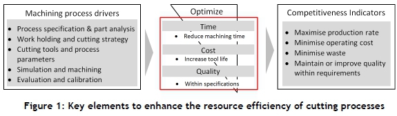
Machining of metals is an extremely important manufacturing technology, since it is estimated that, in terms of value, about 15 per cent of all mechanical components that are manufactured worldwide are derived directly from machining operations [2]. The goal of any manufacturing company is to reduce cycle time, resources, and cost while maintaining or improving the machined product's performance. The competitive advantage is embedded in the ability to produce parts at a faster production rate than planned, at a lower cost than predicted, and with a part quality better than specified - as illustrated in Figure 1. In order to help process planners and machine operators to achieve this through working towards optimised machining processes, a cost modelling process planning framework has been constructed [3]. As part of this framework there are several input drivers that have an effect on the efficiency and cost of the manufacturing system. These drivers must be managed in such a way as to optimise the internal processes to yield improved products according to the competitiveness indicators.
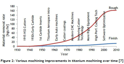
The growing demands on aerospace manufacturers to machine more difficult-to-machine [2] titanium alloys require manufacturers to increase their capabilities and capacities. This requires a better understanding of the tool demands and effective strategies for the milling of Ti6Al4V. Many of the same qualities that enhance Ti6Al4V's appeal for most applications also contribute to it being one of the more difficult materials to machine [4]. This work builds on recent studies [2, 5, 6] that have shown that milling strategies and cutting geometries can have a significant effect on the resource efficiency and performance of the cutting process. This concept of optimising machining operations was realised in the early 1900s when Taylor started to look at the machining economics of turning operations. Since then, many optimisation models and techniques have been developed to determine the best parameters for a cutting operation [2,6]. As shown in Figure 2, the role of machining improvement has levelled off over the past decade [7].
As the manufacturing industry evolves to improve machining efficiency, there is a greater focus on reducing material wastage, environmental impact, cost, and time. Thus there is a need for new technologies or strategies to enable further improvement. Machining performance can generally be enhanced by selecting the ideal cutting tool material, with innovative lubrication strategies, optimising the cutting parameters, or developing new milling strategies [2]. Therefore, in this study the effect of milling strategy and cutting tool geometry (not cutting tool material or coatings) was investigated.
The effect of milling strategy was measured in terms of improving tool life, and the effect of tool geometry was studied in terms of reducing machining time. As indicated in Figure 1, these areas contribute towards improving the production rate and process efficiency. The experiments were divided into two phases. Firstly, the new constant engagement angle milling strategy was compared with a conventional approach using similar cutting tool geometries. Thereafter, a component was milled with different cutting tool geometries and the constant engagement angle milling strategy.
2 MACHINING CHALLENGES IN CUTTING TITANIUM ALLOYS
The choice of a tool, insert, and machining path should be determined with care in order to have an efficient and productive machining operation. This will be influenced by a variety of considerations arising from both the desired end result and the available resources. A better understanding of the milling of titanium alloys will help to enhance tool performance and reduce tool cost. Catastrophic tool failure when milling titanium alloys, due to vibration while in cut, is caused by self-excited chatter [8] and forced vibrations due to the formation of shear localisation [9] and the fluctuating friction force between the tool and chip flow. The combination of these with a low Young's modulus (114 GPa) encourages chatter and work piece movement away from the tool. Work hardening, especially at a low maximum un-deformed chip load, and re-cutting of hard chips can lead to catastrophic tool failure [2].
2.1 Effect of milling strategy
In order to machine a part in the most efficient manner, it is important that the correct strategy is used in combination with the appropriate tool for a specific type of feature [10]. This is also limited by the geometry of the tool, and so it is important to find a balance between the type of tool and the efficiency of the milling strategy.
In rough milling - also defined as first stage machining (FSM) - the design or choice of the type of cutter selected will determine the material removal rate (MRR) possible [cm3/min] and the programming options. The aim is to have a strategy suited to the feature to be machined, giving a maximum MRR that can be balanced with an economic tool life (TL). The description Krof the insert style (round, 45°, or 90°) and the number of teeth selected will have a dramatic effect on the machining strategy and ultimately on the TL and MRR [2]. Although cutting speed (vc) has the highest influence on TL and is the easiest to change, it can be the most sensitive in relation to the thermal load [2]. While a high percentage of the radial immersion increases the MRR, it has been found that the relationship between radial immersion (ae) and tool diameter (ø) is critical. The best balance of high MRR and economic TL is found with ae/ø between 30 and 40 per cent [7]. While round and Krinserts have limited depth of cut, Kr=90° has a cutting depth as deep as the cutter diameter and a length that allows for stable cutting. Importantly for Ti6Al4V, an increase in axial depth of cut (ap) has no detrimental effect on tool life (for Kr=90° cutters) [11].
In finish milling operations - also defined as last stage machining (LSM) - the surface finish is the main criterion, and the productive driving factor is no longer MRR [cm3/min] but finished surface area [cm2/min]. In order to maintain a good surface finish, an increase in the feed rate is limited. Likewise the productivity cannot be increased with ae, as the radial cut is limited to 0.5-1 mm finishing stock [7]. Therefore the critical parameters to optimise finish milling operations are the cutting speed (vc), axial depth of cut (ap), and the number of teeth (z) that can be used to change the speed of area coverage. The apshould be as high as possible, but is restricted by the stability of the cutter (high L/0 %), which can be slender.
In rough and finish cuts the milling strategy also influences both the thermal and the mechanical demands on the cutting tool. In climb (down) milling the effective un-deformed chip thickness rapidly increases to a maximum, and then gradually decreases to zero. Climb milling is normally recommended for titanium alloys, because the instant the cutting tool enters the work piece material it starts to cut, without much initial sliding [12]. While this generates less heat between the tool and the work piece, more of this heat can also dissipate into the thicker chip than is the case with conventional milling at the start of the cut [7]. Climb milling forces tend to push the work piece towards the fixture in the direction of the feed, and the chips are disposed of behind the cutter, leading to easier chip removal [13]. In conventional (up) milling the chip thickness starts at zero and gradually increases to a maximum thickness, after which it decreases to zero. The cutting edge is more susceptible to tribo-chemical failure when exiting the work piece, as the chip thickness is high [7]. In conventional milling of slender Ti6Al4V components, the cut at the start is so light that the cutting tool could slide across the surface of the material instead of cutting. The tool will rub until sufficient pressure is built up and the cutting tool suddenly bites and begins to cut [12]. This rubbing occurs more frequently as flank wear (vB) exceeds 0.15 mm [14].
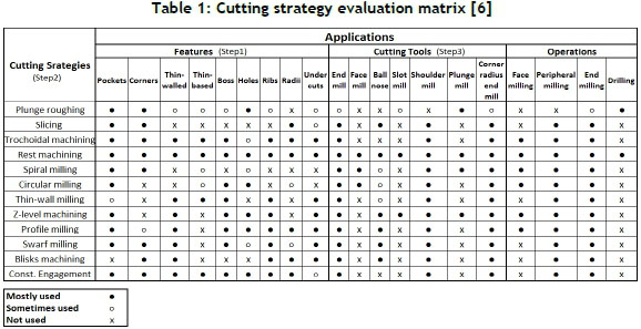
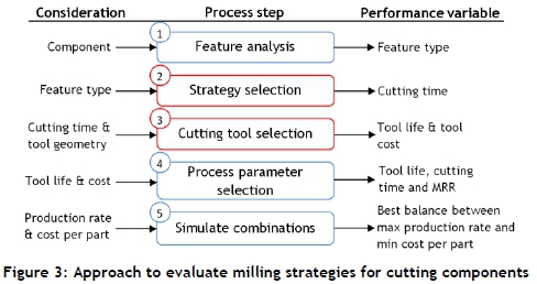
Entry and exit milling strategies should ensure a gradual increase and decrease of the engagement angle as the cutting tool moves into and out of a cut. This decreases the shock on the tool and ensures smaller forces, leading to an increased tool life. Rolling in and out of the cut from the part can reduce the thermal shock and large forces on the cutting tool, as this strategy ensures a gradual change in forces upon entry and exit. The ramp and interpolate strategy does not require a starter hole; and with the use of only one tool, it simply ramps into the material and removes one thin layer at a time by interpolating along the cutting surface. After finishing one layer, the cutter tools ramp to the next layer and start to remove material at that level. As illustrated in the simplified matrix in Table 1 [6], this is a comprehensive process that must be evaluated and weighed off against several factors so that a suitable setup can be selected and implemented [6]. This cutting strategy evaluation forms part of a series of process steps set up in an approach to establish the appropriate combinations of features, cutting tools, and process parameters in working towards an optimised machining process - as illustrated in Figure 3.
Drill and profile milling is the most productive strategy if it is a relatively simple pocket shape that does not require the tool to be changed or successive layers to be machined in certain parts. The drill and plunge strategy can also be used to drill consecutive holes by making overlapping plunges with a plunge-milling tool or a specialised drill. The 'eight-to-one' milling strategy (thin wall milling) developed by the Boeing Research and Technology group states that the maximum axial depth of cut should not be greater than eight times the remaining thickness of the wall or rib adjacent to the cut. If a thin-walled part is machined at full depth, it is likely that it will deflect and that vibrations will occur, making machining very difficult. If the part is machined in successive steps using the 'eight-to-one', the part will be supported all the way to the final cut, thus reducing any vibrations in the structure [6].
Spiral milling strategies have slightly longer cycle times, but increase the efficiency of the pocketing operation and yield longer tool lives. Slicing strategies also help to keep the mechanical load constant, especially when the cutting tool moves into corners. Plunge and sweep strategies help to keep the forces (mechanical loads) on the cutting tool constant, since the z-axis provides the most stable line of work; while the side milling removes or 'sweeps out' the rest of the material. Similarly, trochoidal machining is a milling process where the tool path continually re-crosses itself as the tool feeds through an outline of constant radius arcs. Trochoidal machining is therefore appropriate to use in high speed machining (HSM), as the cutting tool always moves along a curve with a constant radius, and this also makes it possible to maintain a relatively consistent feed rate [6].
With constant engagement angle strategies (Figure 4(a)) the focus is on keeping the engagement angle constant throughout the cutting operation. The best engagement angle is determined according to the geometry of the part, so that the whole part is machined while the engagement angle is controlled accordingly. By adapting the engagement angle, this strategy reduces the forces on the cutting tool so that a greater depth of cuts can be used than in conventional strategies (Figure 4(b) and (c)). This is a new strategy, and its development aligns with the current difficult with machining materials such as titanium. This strategy was evaluated alongside a conventional strategy as part of this study. By controlling the engagement angle, it can maintain a constant feed rate throughout the cutting operation. The advantages of using such a strategy are [15]:
-
No tool overloading or vibration leads to improved tool life
-
No shock loading leads to reduced chipping on flutes
-
Constant cutting edge temperature prolongs the life of the tool coating
-
Step-downs of two to three times the diameter can be used so that the tool wear is distributed evenly over a much larger cutting surface
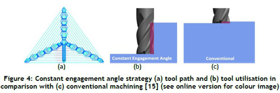
With conventional machining the machine may not maintain the programmed feed rate, due to the forces encountered in the corners. Also, due to the smaller depth of cut, the tool is not used to its full potential, and much longer tool paths are used. With a constant engagement strategy the tool paths are shorter, the use of the cutting tool is better, and the constant feed rate produces a better material removal rate and a reduced cutting time [15].
2.2 Effect of cutting tool geometry
The tool geometry has an important effect on cutting forces that provide essential information about productive machining. The positive effect of appropriate cutting edge geometry on the cutting performance has been recorded in publications [5,16]. Ernst and Merchant [17] explained the chip formation process when analysing the cutting process. They claimed that the chip was formed in the shear plane and was shaped in the sliding plane. Therefore the shear angle is a characteristic variable, and depends on cleaving (wedge) angle and friction. The cutting forces and temperature contributed in the primary shear, chamfer and sticking, and sliding zones are expressed as a function of unknown shear angle, and known friction constants on the rake face and temperature modified flow stress in each zone [18].
A higher shear plane angle means a smaller shear plane, which means lower shear force, cutting forces, power, and temperature. Increasing the negative rake angle increases the tool-chip contact area, causing larger cutting forces because of high friction forces in the tool-chip interface. The rake face of the tool is oriented at an angle called the rake angle. The rake angle is measured to a plane perpen of chip flow, adicular to the surface of the work piece. The rake face determines the directionnd has a large influence of cutting resistance, chip formation and disposal, cutting temperature, and tool life.
A positive rake angle will be used on a soft work piece that is easily machined and when the work piece or machine has poor rigidity. An increase in the positive direction of the rake angle improves the sharpness of the cutting edge that decreases cutting power but lowers the cutting edge strength. On the other hand, when cutting edge strength is needed, such as with interrupted cutting and hard work pieces, a reduction of the rake angle even into negative values is favourable [2]. When machining titanium, the general rule is to use a 5°-20° positive rake angle. Research [12] found that by increasing the rake angle by 1° the cutting power can decrease by 1 per cent. The increase in the sharpness of the tool allows the insert to be used on a machine that is less powerful and has poor rigidity. The increase in rake angle also reduces the time the chip is in contact with the insert, reducing tool wear on the rake face caused by thermally-activated tool wear. A land is used as a compromise between a sharp cutting edge and the strength of a dull tool.
It is also well-known that increasing the clearance angle can decrease flank wear. This angle prevents friction between the flank face and work piece, which can help to reduce the cutting forces and abrasive types of tool wear [2]. This larger clearance angle will also reduce rubbing and metal build-up. However, for milling titanium alloys, the use of such high clearance angles can decrease the included angle between the rake face and the clearance face, and can make the cutting edge brittle for rough cuts. The following are the desirable properties for the ideal cutting tool material for cutting titanium alloys [2]:
-
Small grain size to be able to produce a sharp cutting edge
-
High hardness, including high hot hardness, to provide excellent abrasive wear resistance
-
Good toughness (high transverse rupture strength and fracture toughness) to maintain a sharp cutting edge without chipping or deformation under a cutting force's dynamic action
-
Good thermal conductivity to remove heat from the cutting zone
-
Thermal stability to maintain integrity at cutting temperatures
-
Low chemical affinity or reactivity to the work piece material
Cutting tools are subjected to very high mechanical and thermal demands with modern machining technologies such as high speed machining (HSM), high performance machining (HPM), and dry machining. With the focus on HPM, the thermal and mechanical stresses induced are further enhanced when titanium alloys with a low thermal conductivity are machined. Currently a variety of cutting materials are available for different cutting applications: carbon steel, high speed steel, cast cobalt alloys, cemented carbide, cermets, ceramics, diamond, and boron nitride [14].
3 EXPERIMENTAL SETUP AND DESIGN
In collaboration with industrial partners, two benchmark aerospace components were identified, as illustrated in Figure 5. All the machining experiments were done using a Hermle C40U 5-axis milling machine, and the CAM programming was done using PowerMill from Delcam. The flank wear (vB) increments were measured using an Olympus GX 51 optical microscope with wear analysis software.
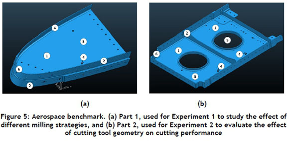
The research study was divided into two phases, as illustrated in Figure 6. The component in Figure 5 (a) will be referred to as Part 1. This component was used to study the effects of milling strategy on cutting performance. The component in Figure 5 (b) will be referred to as Part 2, which was used in experiment 2 to evaluate the effect of cutting tool geometry on cutting performance. Both Part 1 and Part 2 are real aerospace parts, and are representative of most of the typical features that can be found on these types of parts.

After a thorough literature study, the effects of different milling strategies on cutting performance of titanium alloys were investigated in experiment 1. Thereafter, the effects of different cutting tool geometries with a constant milling strategy were studied in experiment 2. Both experiments included two cutting iterations.
3.1 Experiment 1: Different milling strategies with constant cutting tool geometry
Part 1 was manufactured for two iterations using the same tools, but with different cutting strategies. The first type of cutting strategy was a conventional tool path that consisted of contour tool paths conforming to the shape of the part. With this strategy the tools failed in a very short period of time, leading to high tooling costs. Other similar tool paths were tested for the features illustrated in Figure 5: pockets (1), thin walls/ribs (2), thin base (3), undercuts (4), holes (5), and radii (6); but all led to very short tool lives - an indication that titanium is not well suited to be machined with conventional tool path strategies. This was attributed to the material properties of titanium as discussed earlier, which caused the tool to be overloaded and therefore resulted in premature failure.
The second type of cutting strategy that was tested is called a constant engagement angle strategy, in which the tool paths are created such that the engagement angle on the tool never exceeds a specified value. This ensures a more constant load on the tool and prevents overloads, regardless of the type of geometry that is machined.
3.2 Experiment 2: Different cutting tool geometries with constant milling strategy
In this experiment the constant engagement cutting strategy was used to rough out both parts, but different cutting tools were used. The cutting strategy was selected based on the results that were obtained from Experiment 1. Part 1 was machined with a traditional end mill (tool M1) that was flat at the bottom, and the second part was machined using a cutting tool with an angled land on the rake side of the tool (tool M2).
The geometry of a traditional end mill means that it is not possible to machine a pocket from start to finish, as the tool cannot ramp into the material. As illustrated in Figure 7(a), start holes had to be machined in all the locations where the tool paths started so that the end mill could move down the hole before cutting with the periphery of the cutter. This resulted in additional machining time, and also introduced an additional risk of tool failure, due to misaligned toolpaths between the start holes and the cutting toolpaths.
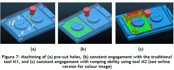
The first machining iteration for Part 2 (Figure 7(b)) was done in levels, and for every set of toolpaths it was required first to machine start holes so that the end mill could start cutting from within the machined hole. For the second iteration of Part 2 (Figure 7(c)), a cutter with an angled geometry at the bottom was used. As discussed earlier, this geometry allowed the end mill to be used for both ramp milling and peripheral milling. This eliminated the need for start holes, and allowed the cutter to ramp down to the cutting depth from which it could continue removing material with the periphery of the cutter with one depth of cut, as illustrated in Figure 7(c). The geometry of the tool from manufacturer 1 (tool M1) is illustrated in Figure 8(a), and the geometry of the tool from manufacturer 2 (referred to as tool M2) is illustrated in Figure 8(b). These images were created using a ZOLLER Smile 400 -Pilot 3.0 universal tool pre-setter and measuring machine.
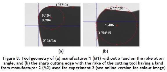
Tool M1 has a tip radius that is rounded from the periphery of the cutter to the end of the cutter. This radius is approximately 1 mm, and serves to distribute the forces over the tip of the cutting tool. The end of tool M1 has an angle of approximately 1°, which is too small to provide clearance for cutting with the end of the mill. For this reason this tool cannot be used to ramp into material. It can only cut with the periphery of the cutter, and so when pockets are machined it will be necessary first to machine start holes. This cutter can then move down to the depth of cut within the hole to start machining.
Tool M2 has a sharp cutting edge, with the rake of the cutting tool having a 6°land. The theoretical result is a sharp tool with increased cutting strength. This clearance allows the tool to cut with the periphery as well as the bottom of the end mill. Tool M2 also has a tip radius, but it forms a sharp angle where it meets the bottom flute of the cutter. Another geometric aspect of the tools is the angle of the flutes. Tool M1 has variable helix angles of 45 and 43.5 degrees, as illustrated in Figure 9(a) and (b). Tool M2 has constant helix angles of approximately 35.5 degrees, as shown in Figure 9(c).
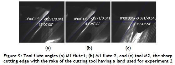
The variable helix angles help to reduce chatter by preventing attenuation of cutting vibrations, and are especially suited for thin-walled parts as found in aerospace components [7]. Both tools have through spindle coolant holes, but with different geometries. Tool M1 has multiple holes between the flutes, which deliver coolant along the cutting edges, and tool M2 has one coolant hole through the centre, which delivers coolant at the end of the cutting tool.
4 EXPERIMENTAL RESULTS AND DISCUSSION
The effects of different milling strategies on the cutting performance of titanium alloys were first studied. Thereafter, the effects of different cutting tool geometries with a constant milling strategy were investigated. The effects of the cooling setups on the cutting process were found to perform well for the purpose of lubrication, cooling, and evacuating chips.
4.1 Experiment 1: Different milling strategies with constant cutting tool geometries
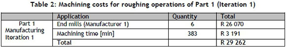
Part 1 was manufactured using conventional cutting strategies. As discussed, these strategies were not very effective in removing the material, as the average tool life was very short, resulting in high tooling costs. The roughing machining time and costs are summarised in Table 2.
For the second machining iteration of Part 1, the same manufacturer's tools were used, but a different cutting strategy was implemented. This cutting strategy made use of a constant engagement angle strategy that resulted in improved tool life and reduced costs, as illustrated in Table 3.
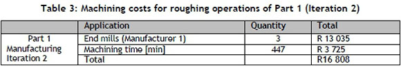
The combination of expensive cutting tools required to machine titanium and an improved tool life led to a significant reduction in the overall machining costs. As illustrated in Table 2 and Table 3, there was a 50 per cent reduction in the number of tools used, which led to an overall reduction of the machining costs. A summary of the machining performance improvements that were attained for Part 1 in experiment 1 is given in Figure 10. This is given as a percentage reduction or increase for cost, time, and cutting tools respectively for the two manufacturing iterations of Part 1. The first iteration of Part 1 is the benchmark against which the changes are measured.
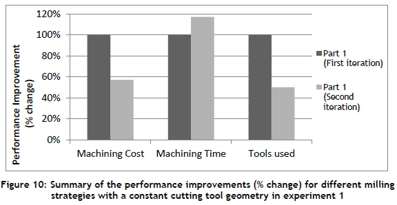
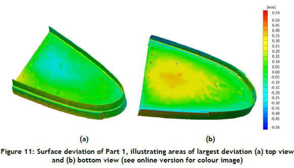
There was a 17 per cent increase in the machining time due to the nature of the constant engagement tool paths; but the additional cost of this was small in comparison with the tooling cost. The significant reduction in tooling costs outweighed the small increase in machining time (cost). There was thus an overall cost reduction of 43 per cent for the roughing operations. The longer tool lives that resulted in a 50 per cent tool saving will lead to fewer tool changes and setups, and so machining time will be reduced. Apart from these improvements, another critical factor is the form accuracy of the finished part (Figure 10). This must adhere to the quality standards set out by the aerospace industry in order to validate the improved cutting strategy. The surface accuracy was measured using a geometrical optical measurement (GOM) scanner. The measured data is compared to the original 3D model to show any deviations in the final machined part.
The biggest deviation of 490μm was recorded in the two corners of the changing radii on the outer edge of the part. These can be attributed to the small corner radius that could not be aligned exactly with the toolpath. However, the tolerance for an aerospace part of this size is 500μm; and as shown in Figure 11 (a) and (b), this part was finished within this specification.
4.2 Experiment 2: Different cutting tool geometries with constant milling strategy
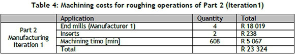
The second machining experiment with Part 2 used the same constant engagement cutting strategy, but different cutting tool geometries. The first machining iteration of Part 2 was done using the cutting tools from manufacturer 1. The second machining iteration of Part 2 was done using cutting tools from manufacturer 2. The costs for machining iteration 1 of Part 2 are summarised in Table 4.
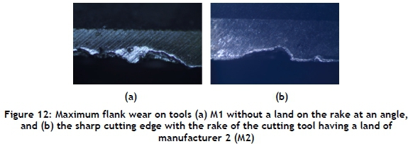
Without the need for start holes, shorter cutting programmes were used, leading to reduced machining times. In addition to the time saving, fewer tools were used because full depth machining uses the entire cutting edge of the end mill, and so more material can be removed per cutting tool. The maximum flank wear on the second tool progressed slower than on the first tool, due to the improved geometry of the end mill.
The maximum flank wear that was recorded for the cutting tools M1 and M2 is illustrated in Figure 12(a) and (b) respectively. As a result of a thicker flank face on the tool from manufacturer 2, a lower magnification had to be used in order to make the measurements. Figure 12(a) was recorded at a magnification of X100 and (b) at a magnification of X50. As Figure 12 shows, the two main types of tool deterioration for both tools are a combination of flank wear (vB) and chipping.
Cutting at full depth was only possible due to the cutting strategy that controlled the engagement angle throughout the operation. Therefore the cutting forces were kept within a manageable range. Using these parameters with a conventional cutting strategy would lead to immediate failure, as the cutting forces would be too high. This was confirmed with the first cuts of the part. The roughing time and costs for the second part are summarised in Table 5.
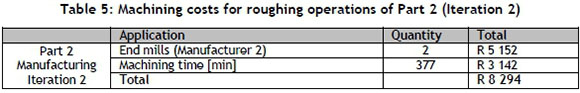
For the second part there was a 50 per cent reduction in the number of tools used, and a 38 per cent reduction in the roughing machining time. As discussed above, the main reason for these improvements was the improved toolpath, fixture design, and geometry of the tools. The costs associated with the tools are only included for illustrative purposes and not for comparison. Since the different tooling manufacturers have different prices, these will not be used as part of the process improvement.
A summary of the machining performance improvements that were attained for the two titanium parts using advanced cutting strategies and tools are given in Figure 13. This is given as a percentage reduction for time and cutting tools respectively for the two manufacturing iterations of Part 2. The first iteration of Part 2 is the benchmark against which the changes are measured.
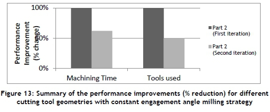
The 38 per cent improvement in machining time, combined with longer tool lives (50 per cent tool savings), has the potential for cost savings in a production setup. With longer tool lives, fewer tool changes are necessary and thus further time and cost savings can be achieved. The wear curves for the tools from the two manufacturers are shown in Figure 14. The tool from manufacturer 1 is labelled M1, and that of manufacturer 2 is labelled M2.
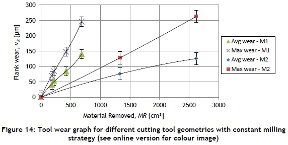
The 'average wear' is the uniform wear that was measured over the entire length of the cutting edges. The 'maximum wear' is the largest wear mark that was recorded during each measurement interval. The wear curve for the tool M1 has a steeper curve, indicating a higher wear rate than the tool with a land on the rake side of the cutting edge. The surface accuracy of Part 2 was also measured to validate the cutting performance of the improved tool geometry. As illustrated in Figure 15, the biggest deviation of 430 μm was recorded on the upper left hand corner in the bottom view of Figure 15 (b). This was due to insufficient support from the fixture on the outer most edge of the part, and can be improved with a more rigid fixture setup.
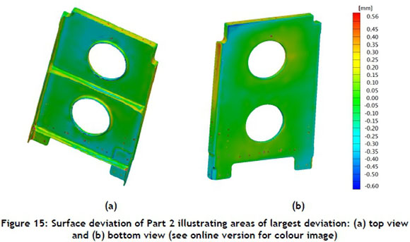
As with Part 1, the tolerance requirement of Part 2 is also 500μm; and as illustrated in Figure 14 (a) and (b), this part was also finished within tolerance. These incremental improvements made it possible to enhance the overall performance of the cutting process.
5 CONCLUSION
Machining titanium remains a challenge, and so it requires novel approaches to improve machining performance. Recent studies have shown that milling strategies and cutting geometries can have a significant effect on the resource efficiency and performance of the cutting process. A theoretical evaluation of these parameters' effects on the cutting operation was performed, and then was tested and validated with two experimental setups. In the first setup the effect of the cutting strategy was evaluated by keeping the tool geometry constant while the strategy was varied. The outcome revealed that the use of the innovative constant engagement angle milling strategy enabled cost savings of more than 40 per cent per part in comparison with conventional cutting strategies.
In the second experimental setup the effect of the tool geometry was evaluated by keeping the cutting strategy constant while the tool geometry was changed. The results revealed that a sharp cutting edge with the rake of the cutting tool having a land performed better than cutting tools without a land on the rake at an angle. A reduction of 38 per cent in machining time was achieved by using these tools with improved geometries. Together these results support the recent studies on performance improvements, and show that incremental improvements contribute towards enhancing the overall performance of machining titanium.
ACKNOWLEDGEMENTS
This work was funded by the South African Department of Science and Technology (DST).
REFERENCES
[1] Xu, X.W. and Newman, S.T. 2006. Making CNC machine tools more open, interoperable and intelligent-a review of the technologies, Computers in Industry, 57, pp 141-152. [ Links ]
[2] Oosthuizen, G.A., Akdogan, G., Dimitrov D. and Treurnicht, N.F. 2010. A review of the machinability of titanium alloys, Research and Development Journal of the South African Institution of Mechanical Engineering, 26, pp 43-52. [ Links ]
[3] Dimitrov, D., Conradie, P. and Oosthuizen, G.A. 2013. A process planning framework for milling of titanium alloys, International Conference on Competitive Manufacturing, Stellenbosch. [ Links ]
[4] Byrne, G., Dornfeld, D. and Denkena, B. 2003. Advancing cutting technology, Annals of CIRP, 52(2), pp 483-508. [ Links ]
[5] Bouzakis, K., Michailidis, N., Skordaris, G., Kombogiannis, S., Hadjiyiannis, S., Efstathiou, K., Pavlidou, E., Erkens, G., Rambadt, S. and Wirth, I. 2003. Optimisation of the cutting edge roundness and its manufacturing procedures of cemented carbide inserts, to improve their milling performance after a PVD coating deposition, Surface and Coatings Technology, 163-164(1), pp 625-630. [ Links ]
[6] Conradie, P., Dimitrov, D. and Saxer, M. 2013. Cutting strategy selection for titanium machining - A key for cost savings, 25th Annual South African Institute for Industrial Engineering Conference, Stellenbosch. [ Links ]
[7] Oosthuizen, G.A. 2010. Wear characterisation in milling of Ti6Al4V - A wear map approach, PhD dissertation, Stellenbosch University, South Africa. [ Links ]
[8] Altintas, Y. and Weck, M. 2004. Chatter stability of metal cutting and grinding, Annals of CIRP, 53(2), pp 619-642. [ Links ]
[9] Komanduri, R. and Hou, Z.-B. 2002. On thermoplastic shear instability in the machining of a titanium alloy (Ti-6Al-4V), Metallurgical and Materials Transactions, 33(9), pp 2995-3010. [ Links ]
[10] Lee, J.Y. and Kim, K. 1998. A feature-based approach to extracting machining features, Computer-Aided Design, 30(13), pp 1019-1035. [ Links ]
[11] Budak, E. 2000. Improving productivity and part quality in milling of titanium based impellers by chatter suppression and force control, Annals of CIRP, 49(1), pp 31-36. [ Links ]
[12] Mitsubishi Materials Corporation. 2006. Mitsubishi Tooling Technology, 1st edition, MMC. [ Links ]
[13] Thomas, M., Turner, S. and Jackson, M. 2010. Microstructural damage during high-speed milling of titanium alloys, Scripta Materialia, 62(5), pp 250-253. [ Links ]
[14] Arrazola, P.-J., Garay, A., Iriarte, L.-M., Armendia, M., Marya, S. and Le Maftre, F. 2009. Machinability of titanium alloys (Ti6Al4V and Ti555.3), Journal of Materials Processing Technology, 209(5), pp 2223-2230. [ Links ]
[15] Delcam, 2012. Vortex & Machine DNA, Birmingham. [ Links ]
[16] Rech, J. 2006. Influence of cutting edge preparation on the wear resistance in high speed dry gear hobbing, Wear, 261(5-6), pp 505-512. [ Links ]
[17] Ernst, H. and Merchant, M. 1941. Chip formation, friction and high quality machined surfaces, Transactions of American Society for Metals, 29(1), pp 299-328. [ Links ]
[18] Lazoglu, I. and Altintas, Y. 2002. Prediction of tool and chip temperature in continuous and interrupted machining, International Journal of Machine Tools and Manufacturing, 42(1), pp 1011-1022. [ Links ]
# This article is an extension of a paper presented at the 15 Annual International RAPDASA conference held in Stellenbosch, South Africa in November 2014.
* Corresponding author
1 The author is enrolled for a PhD (Industrial Engineering) degree in the Department of Industrial Engineering, Stellenbosch University.

