


Services on Demand
Article
 English (pdf)
 Article in xml format
 Article references
Indicators

Related links
-
 Cited by Google
 -
 Similars in Google
Share

 Permalink
South African Journal of Industrial Engineering
On-line version ISSN 2224-7890
Print version ISSN 1012-277X
S. Afr. J. Ind. Eng. vol.26 n.1 Pretoria May. 2015
GENERAL ARTICLES
A thin, hardware-supported middleware management system for reconfigurable manufacturing systems
R.R.P. McLean; J. Padayachee; G. Bright
Discipline of Mechanical Engineering University of KwaZulu-Natal, South Africa. 214584328@stu.ukzn.ac.za, padayacheej@ukzn.ac.za, brightg@ukzn.ac.za
ABSTRACT
The reconfigurable manufacturing system (RMS) paradigm was introduced in response to the need for a manufacturing environment that can handle high-frequency market-driven change. Although this has resulted in much research into the implementation of such a system, there is currently a gap in the technology covering the rapid establishment of control after a reconfiguration. This gap involves the detection of the factory floor's state, and the communication link between the factory floor and the high-level software (ERP and MES). This paper proposes a thin, hardware-supported middleware management system to support the reconfiguration process and to support industrial implementation to the RMS paradigm.
OPSOMMING
Die herkonfigureerbare vervaardigingstelsel paradigma is ontwikkel in reaksie op die behoefte aan 'n vervaardigingsomgewing wat hoë frekwensie, markgedrewe verandering kan hanteer. Alhoewel baie navorsing tot die implementering van so 'n stelsel gedoen is, bestaan daar steeds 'n gaping in die tegnologie tot die spoedige beheername van só 'n stelsel na 'n herkonfigurasie. Hierdie gaping behels die bepaling van die aanlegvloer se toestand en die kommunikasie tussen die aanlegvloer en die hoëvlak sagteware (soos ondernemingshulpbronbeplanning). 'n Dun, hardeware ondersteunde oorbruggingsbestuursagteware om die herkonfigurasie proses te steun en om die industriële implementering van herkonfigureerbare vervaardigingstelsels te bevorder, word voorgestel.
1 INTRODUCTION TO THE RECONFIGURABLE MANUFACTURING SYSTEM (RMS) PARADIGM
The frequency and unpredictability of changes in modern industry requires a manufacturing system capable of a rapid response to change [1-3]. This market-driven necessity has led to a shift in the focus of manufacturing research towards the responsiveness of systems. Research into Reconfigurable Manufacturing Systems (RMSs) has been underway since 1999, when the notion was introduced by Koren et al. [3] at the University of Michigan. This research was driven by the need for production systems that are able to evolve economically according to changes in markets and products [1-5]. The paper of Koren et al. [3] has been the basis for the RMS paradigm and for what are seen as its five essential characteristics: 'modularity', 'integrability', 'diagnosability', 'convertibility', and 'customisation'. Other authors have since elaborated on these characteristics [6,7]. A sixth characteristic has since been defined: 'scalability' [4,5,8]. RMS aims for a system that can respond to new market needs rapidly, economically, efficiently, and effectively. This design for reconfigurability is the central concept of RMS, and it makes RMS an economically attractive system for high variety and mass customisation manufacturing (MCM) [1].
The literature contains explanations of the six key characteristics of the RMS paradigm for a high level of reconfigurability [3,5-7]. 'Modularity' in an RMS is the requirement that important components of the system are modular in design and that they are changed and replaced seamlessly, allowing for the configuration of the RMS to be changed quickly and efficiently. 'Integrability' is important because it means that the RMS can adopt new technology and integrate the new technology with older hardware and software in the RMS, aiding the system's ability to be updated and added to without major interruption. Detecting problems in the quality of the output product and in the reliability of the RMS is vital for quick ramp-up times, and it covers the 'diagnosability' characteristic. 'Convertibility' is required for a rapid change-over between products already being manufactured, and enables the timely and efficient adoption of new products into the RMS. 'Customisation' in an RMS means that the flexibility of the RMS (in both hardware and software) should only extend to a particular product family or families. This prevents the RMS from being over-capable and thus reduces the cost of the system. 'Scalability' stems from the requirement that an RMS handle market uncertainty and fluctuations in demand, while maintaining a low cost. These key attributes allow an RMS, among other things, to produce product variants, adapt to volume changes, handle product uncertainty and complexity, adopt new technology, and shorten delivery time in changing markets - all while maintaining a low cost [3,8]. The need to handle these changes and demands is the driving force behind reconfiguration. RMSs must produce a varied set of products in order to seize a lucrative gap in the marketplace [3,9].
Reconfigurable machine tools (RMTs) are an essential component of RMSs; they aim to combine the best attributes of the dedicated machine tool (DMT), which is used in most high-volume manufacturing, with the computer numerical control (CNC) machine, which is used in lower-volume industries [10,11]. The RMT aims to have the ability to produce some finite subset of parts or operations within a family [11] while maintaining the ability to produce high volumes. RMTs provide this functionality by allowing software and hardware modules to be interchanged or shifted to a different position, which in turn provides broader functionality. For the purpose of this paper, the combination machine configurations and their positions on the level of the factory floor are referred to as the 'factory state' or 'RMS state'.
2 RECONFIGURATION IN THE RMS PARADIGM
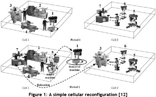
There are many reasons for an RMS to evolve its configuration. These changes are mostly market-driven, with new competition and new products forcing very frequent production changes. An RMS should handle market changes with a rapid and cost-effective reconfiguration [3,5]. An RMS can evolve in a combination of the following ways in order to adapt to new requirements: machines can change position within the system, or they can be removed from/added to the system, or the physical configuration of the machines may be altered and/or the operational program can be changed. The illustration below (Figure 1) shows an example of physical reconfiguration in a cellular system. For the change from Period 1 to Period 2, Machine 1 is removed from the system, Machine 3 is removed from Cell 1 and placed in Cell 2, and Machine 7 is moved from Cell 2 to Cell 1 (Machines 3 and 7 are swapped).
2.1 Enumeration of RMS states
The combination of possible changes in an RMS leads to a huge number of configurations. In the literature [6], a formula is given for the number of possible factory layout configurations, Κ (where Ν is the number of machines and m is the number of possible stages in which they can be arranged). Equation 1 gives the number if m is 'exact', and Eq 2 gives the number if m is defined as 'up-to':

However, each RMT also has its own finite number of configurations, which changes the effective configuration of the RMS. The formula for the total enumeration of possible factory floor states must include the number of possible machine layouts on the factory floor, and the number of configurations of those machines themselves. There are two parameters to consider for the physical configuration of a modular RMT: the number of reconfigurable aspects, , and the number of possible configurations of each of these aspects, . The number of configurations that are redundant or impossible, , should also be taken into account and subtracted; this should be determined empirically. The software changes that are possible with no change in hardware, s, have to be found empirically and added, giving the formula for the number of configurations of a machine:
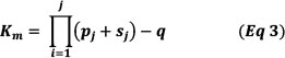
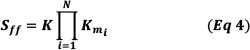
This can be merged with Equation 1 or Equation 2 to give the total number of factory floor states, Sff:
Consider the example of an RMS with 12 machines that can be arranged in exactly four different stages. A summary of the machines is given below:
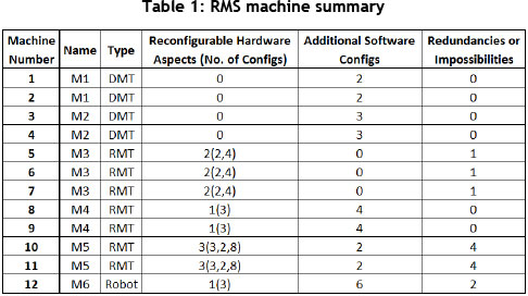
From Equation 1 we find that Κ = 165. Note that a DMT has no changeable hardware, and thus its number of configurations is equal to the number of programs it can run. Using Equation 1, we find the following data for Km: M1 - 2, M2 - 3, M3 - 7, M4 - 7, M5 - 46, M6 -9. Using this data in Equation 2, we find that 20,083,140 configurations are possible in this simple RMS. It is clear that not all of these configurations are realistic or useful, but this displays the flexibility of RMSs.
3 THE NEED FOR SUPPORTING TECHNOLOGY IN RMS
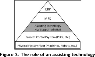
RMSs require physical and software reconfiguration in order to handle the required changes. Industrial control and planning uses levels of software in the order that is shown in Figure 2. Enterprise Resource Planning (ERP) and Manufacturing Execution System (MES) [12-14] software, supported by engineers using knowledge and simulations, makes reconfiguration decisions and produces production plans and scheduling that need to be passed down to the rest of the system [12]. Once the machine moving and tool/module changes have taken place, the MES, ERP, and design engineer need real information on the new factory floor's state in order to create a new operations plan that can be passed to the controllers. When this process is done manually, it is time consuming and may be prone to errors; speeding this process up can drastically reduce ramp-up time, which is a core goal of the RMS paradigm [1,3,7]. It is the goal of this supporting technology to speed this process up.
3.1 Communication
During a reconfiguration, the machines are moved and the wireless nature of the middleware management system (MMS) (as presented in this paper) allows this movement to take place without the disruption of communications. Also, no communications re-wiring is needed after the reconfiguration has taken place, thus shortening the ramp-up time.
3.2 State detection
There is currently research in the literature on the intelligent reconfiguration of RMS [1518] and on middleware that is capable of handling the heterogeneous nature of the RMS controllers that use software-based Holonic methods [19-21]. This literature does not, however, address factory floor state detection. Traditional Supervisory Control and Data Acquisition (SCADA) also has no support for reconfiguration; it cannot detect the state of the factory floor, and does not allow for re-programming after a reconfiguration. This supporting technology assists reconfiguration and provides a communication network for wireless SCADA. Figure 2 shows where supporting technology is needed to create a link between the controllers and the decision-makers.
3.3 Control of homogeneous entities
The current software-intensive method [20] routes data along the existing communication infrastructure of the RMS, and is a traditional middleware system; the heterogeneity is handled using software that is configured to communicate with the heterogeneous entities. The need to gather factory floor state for the control elements slows the ramp-up time of the RMS when done manually, inhibiting this core goal. The automation of this process will increase greatly the industrial practicality of RMS.
The thin MMS, which is a new method for handling heterogeneity, also acts as a state detection system that can communicate the factory floor's state to the control elements. Using a hardware-supported middleware system negates the need for a thick software-intensive middleware layer in the control system. A hardware module, the state communication module (SCM), is proposed as a solution to the needs outlined in the previous section. This hardware-supported MMS differs from traditional middleware solutions, such as IceHMS [20], because it shifts much of the burden to a hardware module; it also adds further functionality in the form of a real-time location system (RTLS) and a method for machine configuration detection. The module system was developed to replace the complex middleware layer in the network with a mechatronic hardware solution. A major motivator for this system is the simplicity achieved by using this hardware: the hardware-supported system requires little debugging, and is universal for machine controllers. The MMS presented here is simpler to implement than software-intensive methods. It can also be used as a replacement (including SCADA functionality) or as an addition to an RMS containing standard SCADA because of the universality and modularity of the system. It stands alone as a system, and thus is independent of the current installation, decreasing overall system cost.
The concept uses a microcontroller module with wireless communication, a bit-wise communication link with the machine, and position detection capability. The module is attached to the machine and provides three main functionalities:
1. A means of gathering information on the factory floor after a reconfiguration operation, providing the decision-making software with this information;
2. Passing software reconfiguration information from the MES to the machines; and
3. Feeding supervisory data to the central controller via the wireless network during operation, to be displayed as a SCADA interface.
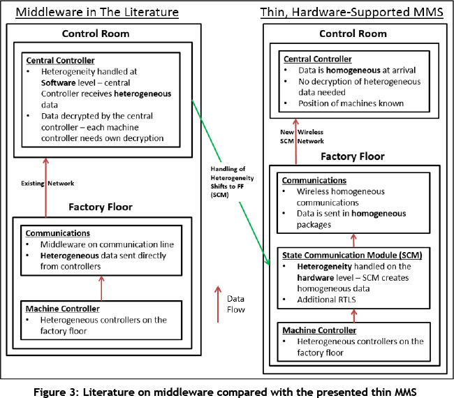
Figure 3 shows how this thin MMS differs from traditional middleware in the literature.
The thin, hardware-supported MMS differs from the current system in the literature because it uses hardware placed on the factory floor to handle heterogeneity and to provide wireless communication. This eradicates the need for complex software that must decrypt the heterogeneous data by using the modules to process the information and send the data in a homogeneous manner understood by the central controller. This allows the system to have no communication wiring, aiding mobility and ramp-up speed. In addition to replacing the need for complex software, the thin, hardware-supported MMS has configuration detection and real-time location capability to allow state detection. The functionality of this design matches the needs of the supporting technology shown in Figure 2. Several aspects of module design were considered in the overall design of the MMS. The discussion and investigation of these is set out in the sections that follow.
4 THE STATE COMMUNICATION MODULE (SCM)
The SCM is an integral part of the MMS, and is the hardware that supports the system in its management of heterogeneity, state detection, and communication.
4.1 Communication between the SCM and the central controller
The literature contains a large amount of research on many different communication techniques, which range from simple wired protocols to internet protocol (IP)-based wireless methods [22]. Each method has its merits and its drawbacks. Initially, a comparison was made between wireless and wired communication, based on data speed, reliability, reconnection time, reliance on current architecture, and cost. Wireless technology was chosen for further development mainly because of its universality and non-reliance on current installations. In addition, wireless technology is a 'future technology', envisioned to grow. It is beneficial to develop a new framework based on emerging technology. For the purpose of RMS specifically, wireless technology has the additional benefit of being portable; the modules can be connected when other wired communications have not been plugged in yet. Because the proposed MMS is envisioned to be implemented internationally and to be used by many engineers who are not licensed to use restricted wireless bands, it must be designed in an unlicensed band.
Electromagnetic interference (EMI) and radio frequency interference (RFI) cause problems with wireless communications in a manufacturing or industrial setting. In high power systems, there is a lot of interference between 10 kHz and 50 MHz from power and signal lines [23]. Variable frequency drives in an industrial setting emit strong interference below 1MHz, but as frequency increases, the level of interference decreases [24]. Unprotected microwave devices that may be present in a factory can also cause major interference in the 2.4 GHz band [25]. The 433 MHz band is not commonly used in the industrial environment, so interference from other radio frequency users is unlikely to be an issue in an industrial setting. Use of cell phones creates interference at 1.8 GHz and at 900 MHz on some networks [26]. TV broadcasts create significant interference in the low 600 MHz range, but these bands are licensed and thus cannot be used in the proposed module. Many wireless protocols were considered; Zigbee® was chosen as a developmental platform.
Zigbee® is a 2.4 GHz specification aimed at scalability and self-organisation that builds on the medium-access control (MAC) layers of the IEEE 802.15.4 specification. New versions are now capable of both mesh networking and peer-to-peer communication [27,28]. Security in a Zigbee® network is not a top priority, but robust security techniques are available for use in the MAC layer. Industrially, Zigbee® has yet to be proven, but popularity and viability are growing with the introduction of new versions. The lack of channel-hopping is of concern to the industrial user of Zigbee®, especially as the network grows in size [27]. Zigbee® is not an ideal solution in terms of performance, and may require a complicated mesh network; but its advantage is that it is very cost-effective (especially for prototyping) when compared with other communications protocols. There is also a large amount of literature and support on using Zigbee®. In addition, the modules (XBee®) are bought preconfigured, reducing prototype development time. As will be discussed in Section 5.3.3, Zigbee® can also be used as a positioning technique.
4.2 Communication between the SCM and the heterogeneous controllers
Communication between the machine controller and the state communication module could be done in a bit-wise fashion or over some simple communications protocol. Many industrial controllers are programmable logic controllers (PLCs), and are capable of reading high/low signals on input pins. However, not all are compatible with another standard protocol without the addition of an add-on module. Other controllers are also generally capable of binary reading, making the option of bit-wise communication practically universal and cost-effective. In addition, although many commonly-available microcontrollers are capable of the simple communication algorithms, every MCU is capable of digital bit-wise binary signalling. Using this bit-wise communication may seem simple, but it is important to note that a 7-bit message can provide 128 different messages.
4.3 State detection
The MMS is able to detect the state of the factory floor using the SCM, and is able to communicate it to the ERP and MES software packages and the design engineer.
4.3.1 Machine configuration detection
The module gathers the physical state of the machine through communications with the machine controller. Research has been conducted [29] into modular control architecture that knows the state of the machine; and in simpler cases this can be hard-coded into the controller. The SCM requests the configuration from the machine controller using a 7-bit signal, and the machine controller can be made to respond with a 7-bit code giving its configuration. The SCM then sends this information to the MMS controller.
4.3.2 Positioning technology
There has been much research into various indoor positioning or localisation techniques; these pieces of modern research were summarised in a thesis by Mautz in 2012 [30], and a version of this work was also published as a journal article [31]. Two broad options described in these works are realistic in the RTLS technique, based on the requirement constraints for the RMS paradigm application of a RTLS. Either the detection technology must be very accurate (±1cm), or a less accurate (±1m) technique could be used along with some artificial intelligence (AI) in order to give accurate data. The AI should be able to produce a realistic and accurate model based on less accurate data. It is clear that the RTLS technique needs to have a range capable of covering a factory floor longer than 50 metres.
The more accurate method is more desirable, as this system would be easier to implement and would output more reliable data. The disadvantage of this, however, is the drastically-increased cost of a system capable of accuracy to the order of one centimetre and a range large enough to cover a factory floor. Tactile and combined polar systems (TCPSs) work in a similar manner to an outdoor global positioning system (GPS), but use stationary beacons installed in the factory. They are highly accurate, and can cover huge areas [32]; but the cost of the system would make the proposed module system practically inaccessible and much less attractive to RMS designers. Ultra-wideband (UWB) systems are very accurate, and so were considered more suitable for the application [33]. While UWB systems are much more financially viable than TCPS, they are still too expensive for the application at hand.
Using a less accurate positioning technique, along with some simple AI to process the raw data into a usable factory floor model, does involve more work than the more accurate techniques listed earlier, but it has the advantage of being far more cost-effective. Using simple AI to process raw positional data allows for the use of cost-effective pseudolites, radio frequency identification (RFID), and other radio frequency (RF) techniques for gathering positional information. These technologies are more financially viable, and should provide a more attractive product to industry. Further investigation has been done into new RF technologies, which include received signal strength indication (RSSI) to help gather positional information. It should be noted that Zigbee® has been developed into reasonably accurate (<1 m resolution) and very cost-effective positioning platforms [34,35]. This lends additional plausibility to the use of this technology as the communication technique for the SCM. By using the same hardware for both communication and localisation, the overall cost of the module was decreased. Using other methods discussed above would have added tens of thousands of Rand (ZAR) to the cost of the system; but because of the lower cost and less reliance on other systems, the industrial implementation becomes more feasible. Multiple algorithms incorporate RSSI from distributed stationary transmitters into an approximate module position. Because of the time periods at hand, multiple measurements can be taken to ensure accuracy.
4.3.3 RTLS algorithms
Once the RSSI ability of the Zigbee® protocol had been chosen (using the XBee® Series 2 hardware), the method for localisation using that RSSI to determine position was considered. With range-based RSSI techniques, the strength of the received wireless signal is used to estimate the distance from the fixed 'satellite' point (hereinafter, 'beacons'). A range-free algorithm is more complex, and uses a comparison of RSSI to determine an approximate position. This method is less susceptible to errors caused by condition changes, and can prove more accurate in some instances [36]. Both methods then use triangulation to calculate the position of the receiver within a certain area [37].
Research has been conducted by Zanca et al. [37] and others [34,36,38] on different RSSI-based localisation algorithms that were considered for use in the MMS. The SCM makes use of a combination method, as described below. The fact that the SCM will always lie within a multilateral shape bordered by beacons means that the accuracy should exceed the resolution quoted in the literature [37].
Equation 5 shows the model for expected received power (pj) at a distance (rj). The received power is given in terms of the distance from a source, the reference power (p0) at a reference distance (r0), and the empirically-determined path loss (n) [39]. This equation can be manipulated (Equation 6) to estimate the distance from the received power and to find the radii in all range-based localisations, including the multilateration in the SCM positioning algorithm.

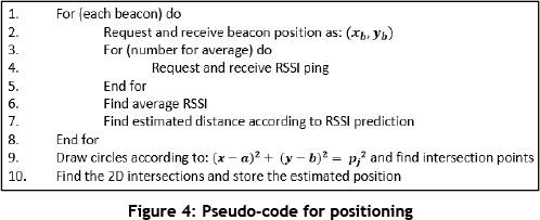
The range-based algorithm on the SCM gathers the RSSI from each beacon multiple times, taking an average to improve accuracy; it then uses Equation 6 to estimate the distance between the module and each beacon. Each point at which two radii from the beacon distance estimations cross each other (within the bounds of the factory floor area; outside intersections are disregarded), a point is stored; a two-dimensional average is taken of these points, and this is the estimated position. Figure 4 shows the operation of the positioning algorithm on the SCM as pseudo-code:
4.4 The SCM in the RMS key characteristics
The SCM was designed specifically as a mechatronic solution to fit into the RMS paradigm; thus it should apply all the key characteristics needed for good re-configurability. The SCM provides 'integrability' by having the ability to be integrated with any existing or future machines, thus being compatible with new technologies, but allowing RMSs with older machine hardware to be catered for. The SCM can also be fitted to a broad variety of machine and mobile robot platforms, and could even be carried by people, helping a large variety of units to be integrated into the RMS. The SCM aids 'customisation' because it is designed to be universal and does not carry excess functionality. The wireless nature of the communication and the ability to operate on battery power affords the SCM the ability to communicate errors before the system is up and running, helping the 'diagnosability' of the RMS. The SCM is fully 'scalable', with the ability to have as many units added to the factory floor as are needed; with any machine addition a SCM can be added, allowing the RMS to be scaled up or down. The ability to fit the SCM to any machine gives it 'modularity' in the RMS. The SCM is designed to speed up the ramp-up time of the RMS, thus allowing the RMS to change at a higher frequency; therefore the SCM directly aids the 'convertibility' of the RMS.
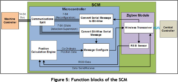
4.5 Inner architecture of the SCM
Figure 5 shows the functions, in block form, needed to create a successful SCM. Each block represents a method or subroutine that the SCM must handle to provide the functionality described in the preceding sections.
5 KNOWLEDGE-BASED ARCHITECTURE AND CLUSTERING FOR A THIN MMS
Knowledge-based systems (KBSs) are a simple, tested branch of AI that use a symbolic and numeric 'knowledge base' (KB) that contains historical data and an 'inference engine' to interpret that data [40]. In the case of MMS for RMS, this knowledge base will be possible machine combinations and compatible configurations.
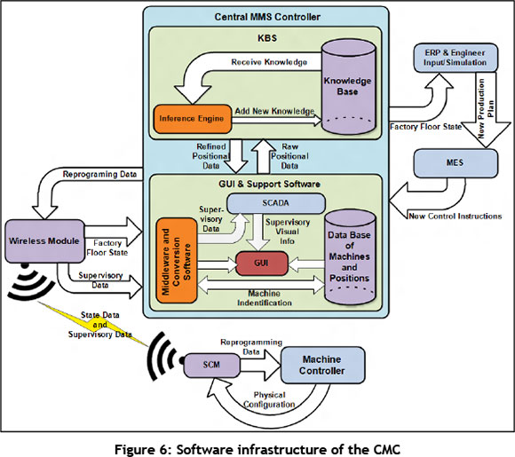
The KBS can use basic factory floor design data, rules, and principles as discussed in previous research papers. Much value is added to the research through the development of the suitable KBS to make more affordable localisation techniques more feasible in the RMS paradigm. Through this intelligence, raw coordinate data fed by the SCMs can be converted by the central controller into one of the factory floor models. This data can then be used by the MES and ERP software. New model states can also be found this way (with some guidance) and added to the knowledge base (KB). Figure 6, presented in Section 7, shows the infrastructure of the MMS software and the interaction between the various software elements.
Before the KBS receives positional data, a clustering algorithm converts it into a cellular model. The KBS for this thin MMS uses known machine states and cell configurations in its KB. These cell configurations contain the known combinations of machines in the cells and which machine configuration combinations are expected to be grouped together. The positioning intelligence works by first running a density-based spatial clustering of applications with noise (DBSCAN) clustering algorithm; this can be simple because of the two-dimensional nature of the positional data provided by the SCMs. Once the clustering has been done, the program assumes each cluster of machines to be a cell. These cells are then analysed, based on the machines present and their states. Each cell is then compared with the KB of cells; the cluster should match some known combination of machines. The matched cluster is then read by the system to be a cell formation. If the cell does not match any of the known cell layouts, then the user is prompted either to run the positioning again or to add a new cell.
6 MMS DESIGN SUMMARY AND OPERATION DESCRIPTION
The MMS is made up of SCMs, positional beacons, and a central MMS controller (CMC). The CMC runs the middleware layer and communicates with the ERP/MES and SCMs. The SCMs gather their positional data by using the beacons, and send this data to the CMC along with the configuration of their machine. The CMC converts this data into a factory floor model that is used by the MES and ERP in the preceding sections. The following figures show the MMS operation: Figure 6 shows the software infrastructure of the MMS, and Figure 7 shows how data flows through the MMS. The Graphical User Interface (GUI) and the support software block controls the MMS. The routine running in this block gives the instruction to scan the factory floor and send the raw positional data (and the instruction to process it) to the KBS. The CMC waits for the data to be gathered and processed, after which the CMS sends this information to the decision-makers (ERP, MES, and engineers) who process it into control instructions sent to the CMC. The CMC converts this into the bit-wise reprogramming data according to the KB, and sends it to the appropriate SCM. Each SCM then changes its message to its machine controller, instructing it to run the program associated with that message. During production, the wireless communication provides a route for supervisory data to flow into a SCADA routine within the support software.
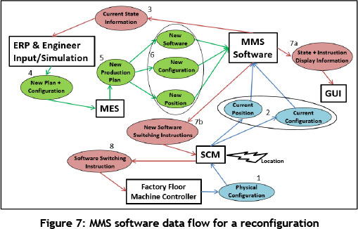
The following steps, which are referred to in Figure 7, start when a new period is about to begin:
1. Configuration from the machine controller is read by the SCM and converted into a configuration message for the CMC.
2. The SCM reads the position and sends it to the CMC, along with the configuration information in a message.
3. The MMS software on the CMC converts this message into a state model and sends it to the decision-makers (ERP and engineer).
4. The decision-makers read the state model and create a new configuration and product plan, which is sent to the MES.
5. The MES (and engineer) creates a product plan and sends it to the controller.
6. The plan comes in the form of new software instructions, new configuration information and new positional instructions.
7. (a) The MMS software displays the new configuration, with machine positions that the reconfiguration must aim to match.
(b) The physical reconstructions have taken place (according to GUI instructions), the software switching instructions are sent to the SCM.
8. The bit-wise converted software instructions are sent to the machine controller.
7 AN EXAMPLE PROBLEM SOLVED BY THE THIN MMS
An example is presented to display the functionality of the MMS in handling a cellular reconfiguration. The following hypothetical example used five machine types, three products, and two periods in a cellular RMS to demonstrate the functionality of the MMS in reconfiguration.
7.1 Aims and objectives
This example aimed to prove the ramp-up time functionality of the thin, hardware-supported MMS. This includes the ability to use the RTLS to find a machine's position, to cluster machine location data into cells, and to use the cellular state data to send appropriate switching data via the wireless SCM to the machine controller.
7.2 An introduction to the investigated case
The example considered here has three products, produced in different mixtures and quantities over two periods, as set out in Table 2, which shows the machine-component incident matrix with the operation sequence of machine use and product demand.
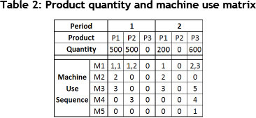
The above matrix shows that this example was solved by a two-cell RMS using five types of machines in different configurations. The change in the required volume of P1 was included to show the scalability of the system, where machine M1 operation was a bottleneck solved by the use of duplicate M1 machines in Period 1 to accommodate the higher required volume.
7.3 A cellular reconfiguration solution
For a cellular RMS, Table 2 requires the factory layouts shown in Figure 8. The two cells were chosen to solve the matrix shown in Table 2 in the same manner that decision-makers (engineers and assisting software) would design a factory floor layout in an industrial setting. This configuration relies on the use of RMTs for all machines other than M5. Each of these RMTs is capable of multiple physical configurations and software programs. All the programs that the machine may use were programmed on to the controllers before this process, along with a case-based reasoning loop that reads the program switching instructions sent by the SCM and selects the appropriate routine to follow.
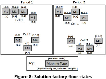
A two-period solution is shown in Figure 8. Handling the change from Period 1 to Period 2 requires the following: one M1 is removed from the system; one M5 is added to Cell 1 from outside the system; and one M3 is added to Cell 2 from outside the system. The configuration of a remaining M1 remains the same; the other M1s adopt a new physical and software configuration, while the M5 is in its first state. M2 and an M3 remain in the same configuration, and M4 and the added M3 are reconfigured into states different from Period 1. Each M1 is capable of adopting any state possible for an M1, and the same is true for each machine type. The MMS resumes operation after the physical reconfiguration of the factory floor and individual machines has been completed. The MMS must scan the factory floor to gather the machine IDs, configurations, and their positions using the SCMs. This information will then be communicated wirelessly to the CMC, which aims to associate the physical configuration of the cells on the factory floor and adjust the manufacturing planning and execution autonomously. This adjustment includes sending program switching instructions to the appropriate SCMs. Thus the MMS must provide a means for rapid system ramp-up by automating and simplifying the process between physical reconfiguration and factory operation.
7.4 Implementation using the thin MMS
The MMS must be validated against the accuracy of the positioning system, the configuration detection, the functionality of the state detection intelligence, and the transmission of the program's switching instructions to the machine controllers. For the purpose of this example, the prototype module and beacons consisted of a Seeeduino Stalker v2.3 microcontroller board for calculations and instructions, with an XBee Series 2 Zigbee® module for communications. The beacons and SCMs were equipped with a two-stage voltage regulator that limited the input voltage of 24V DC to 12V and 5V. The 12V line drove a cooling fan, and the 5V line powered the board. In addition, they had a 3.7V LiPo cell for when the power supply is offline. This cell was kept charged by the Seeeduino's onboard charger from the power supply.
7.4.1 Gathering the machines' configuration
The controller on each machine was configured to respond with a configuration message when prompted by the SCM. The CMC sent a message to each of the SCMs with the instruction to respond with its machine configuration. The SCM set its output pins to [0 0 0 0 0 1 1], which instructed the machine controller to respond with a message that the SCM converted to a serial message for wireless transmission (containing the configuration and machine ID) to the CMC. The CMC interpreted the message from the SCM, and thus could know the configuration of the machine.
7.4.2 Positional data
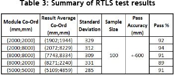
The position-gathering system was tested by gathering positional accuracy data from a single roving node. The following data was gathered using the multilateration RTLS loaded on to the module. The RTLS was tested in a laboratory factory floor environment using four beacons and a mobile module. The module was tested at five points in the 10m x 10m test area, as shown in Table 3, in order to determine accuracy at a variety of points. A result is considered a pass if it locates the module to within the pass accuracy in both the x and y dimensions:
7.4.3 Clustering of data
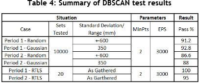
Data gathered by the RTLS needs to be clustered in order for the CMC to recognise physical cells on the factory floor. DBSCAN works by clustering points within a defined radius based on the density of the points over the search area; the scan produces clusters that represent the cells of the factory floor. The DBSCAN algorithm relies on two parameters: a minimum number of points to form a cluster (MinPts), and a maximum size of a point's neighbourhood (EPS); these were found using experimentation. The DBSCAN algorithm copes with the variances in accuracy of the positioning system, the distribution of points in the accuracy as found above. The DBSCAN algorithm was tested in three cases, using data gathered directly from the physical RTLS, using randomly-scattered machine positions based on the pass accuracy in Section 8.4.1, and using Gaussian distributed machine positions based on the standard deviation (from that same section). The generated cases were used to establish the robustness limits of the clustering algorithm in order to display its suitability. A summary of results is shown in Table 4. To pass, the algorithm must identify the cells correctly.
7.4.4 Using the knowledge-based system (KBS)
Logic applied to set theory can explain the function of the KBS. For this section, the following holds: i, j, n, m, p, q, r e N, and it is assumed that the KB is complete in that it contains all the sets needed for the program selection - that is, the KB contains object cells that contain appropriate program switching instructions, and can be matched based on the equivalency of the other attributes of the cell (machine and configuration combinations). Allowances are made for the discovery of a cell not contained in the KB, but these are not discussed here. There is a set of all the possible cells in the KB (Kc) and the cells (c1,c2,..., cn e Kc) are sets of machines, including their configuration (M1,M2,...,Mm e cI). In the KBS, otherwise identical machines with different physical configurations are considered to be different machines. Each unique set of machines (a unique cell) will have a set of all program switching instructions (KP) that must be sent to the machine controllers (P1,P2,...,Pn e Kp). The sets (R1,R2,...,Rq) are the q clusters found by the DBSCAN program, containing machines (Ν1,Ν2,...,Nr e Rt), so that:
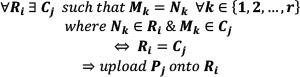
This set process describes the basis for the comparisons made by the inference engine of the KBS, and allows the KBS to send the correct program switching instructions to the appropriate cells. Once the cell had been detected by the RTLS and DBSCAN had been compared with the cells in the KBS and a matching cell was found, then the CMC sent the program switching data to the SCMs of that cell, and could move on to the next cell.
Practically, the KBS was able to use configuration and positional information gathered by the SCMs (and processed by the DBSCAN algorithm), which was stored as an attribute of the machine objects, to compare them accurately with a database of possible manufacturing cells, and to assign them correctly in every case. This assignment allowed the KBS to select a program and to send that information to the SCMs via the CMC.
7.4.5 Software switching using the SCM
Once the KBS had identified the cells and established which program switching instructions were needed, the MMS software sent a serial message to each of the relevant SCMs. For example, upon the switch from Period 1 to Period 2, the only M4 on the floor must switch its software routine from Routine 1 to Routine 2. In this case, the 7-bit bus from the SCM would be set to [0 0 0 0 1 0 1], which was done during the verification of this case study. A Festo CPX PLC was used to verify the operation of the program switching.
7.5 Discussion and conclusion
The positional data found during the testing (Table 3) proved to be very accurate when averages were taken (see average co-ordinates). In the operational case, an average of ten measurements was taken to find the position of the module, which produces data that is accurate to within an absolute 600 mm 95 per cent of the time.
To test the DBSCAN clustering algorithm rigorously, it was fed randomised data within the un-averaged range of the results found by the physical RTLS. The clustering proved to be robust enough to produce correct clusters, even with highly non-ideal positional data, in order to produce correct results 80 per cent of the time. When fed with averaged results within the range discussed in the previous paragraph, the DBSCAN clustering algorithm worked in 97.5 per cent of cases. Thus the combination of the physical RTLS and the DBSCAN clustering algorithm produce highly accurate and usable results. There may be room for improvement in less conducive clustering cases in the DBSCAN algorithm, in order to function at a very high success rate all of the time, possibly with the addition of variable MinPts and EPS parameters, which can change depending on the situation at hand. An improvement in this area would make the system more reliable and industrially sound.
The KBS was able to perform a cell match successfully, and thus select appropriate programs for the machines in each cell. The use of proper object-orientated programming principles in the CMC allowed this process to be carried out simply.
The program switching role of the SCM was tested successfully, and proved to be a simple process once the initial setup of a case-based reasoning system had been implemented in the PLC code itself.
To conclude, this case study proved the effectiveness of the SCM-based concept for a thin, hardware-supported MMS for reducing the time of and automating the ramp-up process, by testing each of the functions necessary for the state discovery and program switching instructions that are needed to automate the ramp-up process after a physical reconfiguration.
8 CONCLUSION
The novel thin, hardware-supported MMS presented in this paper promises to be a good solution to the problems outlined in the earlier sections. The introduction of a fully-functioning reconfiguration-bridging and traditional-SCADA-replacing technology such as the proposed MMS will help the emerging field of RMSs to mature into a more widely-used manufacturing technique. The success of the above case study supported the plausibility of the use of SCMs as an MMS for RMS solution.
Future work on the development of this MMS includes the addition of a fully-functioning SCADA communication pathway along the wireless network, and the continuous improvement of the RTLS algorithms and processing. Improvements to the RTLS would make the system faster and less error-prone, making the system more attractive to the industry.
REFERENCES
[1] Xing, B., Bright, G., Tlale, N.S. and Potgieter, J. 2006. Reconfigurable manufacturing system for agile mass customization manufacturing. International Conference on CAD/CAM, Robotics and Factories of the Future, India, 473-482. [ Links ]
[2] Malhotra, V., Raj, T. and Arora, A. 2009. Reconfigurable manufacturing system: An overview. International Journal of Machine Intelligence, 1(2), 38-46. [ Links ]
[3] Koren, Y., Heisel, U., Jovane, F., Moriwaki, T., Pritschow, G., Ulsoy, G., Van Brussel, H. 1999. Reconfigurable manufacturing systems. Annals of the CIRP, 48(2), 527-540. [ Links ]
[4] Malhotra, V., Raj, T. and Arora, A. 2010. Excellent techniques of manufacturing systems: RMS and FMS. International Journal of Engineering Science and Technology, 2(3), 137-142. [ Links ]
[5] Bi, Z.M., Lang, S.Y.T., Shen, W. and Wang, L. 2008. Reconfigurable manufacturing systems: The state of the art. International Journal of Production Research, 46, 967-992. [ Links ]
[6] Koren, Y. and Shpitalni, M. 2010. Design of reconfigurable manufacturing systems. Journal of Manufacturing Systems, 29(3), 130-141. [ Links ]
[7] Mehrabi, M.G., Ulsoy, A.G. and Koren, Y. 2000. Reconfigurable manufacturing systems: Key to future manufacturing. Journal of Intelligent Manufacturing, 11(4), 403-419. [ Links ]
[8] Bi, Z.M., Lang, S.Y.T., Verner, M. and Orban, P. 2007. Development of reconfigurable machines. The International Journal of Advanced Manufacturing Technology, 39(4), 1227-1251. [ Links ]
[9] Gumasta, K., Gupta, S., Benyoucef, L. and Tiwari, M.K. 2011. Developing a reconfigurability index using multi-attribute utility theory. International Journal of Production Research, 49(6), 1669-1683. [ Links ]
[10] Xing, B., Bright, G., Tlale, N.S. and Potgieter, J. 2007. Reconfigurable modular machine design for reconfigurable manufacturing system. International Conference on Industrial Engineering and Systems Management, Beijing, China, 10-20. [ Links ]
[11] Landers, R., Min, B. and Koren, Y. 2001. Reconfigurable machine tools. CIRP Annals -Manufacturing Technology, 50(1), 269-274. [ Links ]
[12] Safaei, N. and Tavakkoli-Moghaddam, R. 2008. Integrated multi-period cell formation and subcontracting production planning in dynamic cellular manufacturing systems. International Journal of Production Economics, 120(1), 301-314. [ Links ]
[13] Bajahzar, A., Alqahtani, A. and Baslem, A. 2012. A survey study of the enterprise resource planning system. International Conference on Advanced Computer Science Applications and Tech, Kuala Lumpur, Malaysia, 246-252. [ Links ]
[14] Safaei, N., Saidi-Mehrabad, M., Tavakkoli-Moghaddam, R. and Sassani, F. 2007. A fuzzy programming approach for a cell formation problem with dynamic and uncertain conditions. Fuzzy Sets and Systems, 159(2), 215-236. [ Links ]
[15] Xing, B., Nelwamondo, F.V., Battle, K., Gao, W. and Marwala, T. 2009. Application of artificial intelligence (AI) methods for designing and analysis of reconfigurable cellular manufacturing system (RCMS). Paper presented at the 2nd International Conference on Adaptive Science & Technology, Accra, Ghana. [ Links ]
[16] Tang, L., Koren, Y., Yip-Hoi, D.M. and Wang, W. 2006. Computer-aided reconfiguration planning: An artificial intelligence-based approach. Journal of Computing and Information Science in Engineering, 6(3), 230-240. [ Links ]
[17] Horbach, S., Ackerman, J., Muller, E. and Schutze, J. 2011. Building blocks for adaptable factory systems. Robotics and Computer-Integrated Manufacturing, 27(4), 735-740. [ Links ]
[18] Garbie, I. 2014. A methodology for the reconfiguration process in manufacturing systems, Journal of Manufacturing Technology Management, 25(6), 891-915. [ Links ]
[19] Roulet-Dubonnet, O. 2011. Distributed control of flexible manufacturing systems: Implementation of a specialized multi-agent middleware and applications of holonic concepts. Doctoral thesis, Norwegian University of Science and Technology, Norway. [ Links ]
[20] Roulet-Dubonnet, O., Lund, M. and Skavhaug, A. 2013. IceHMS, a middleware for distributed control of manufacturing systems. In: Industrial applications of holonic and multi-agent systems, 1st edition. Berlin, Germany: Springer Berlin Heidelberg, 95-105. [ Links ]
[21] Moyne, J., Korsakas, J., Milas, C., Hobrla, T., Hong, T., Kim, H., Priskorn, J., Sukerkar, K., Wijaya, H., Agarwal, N., Tilbury, D. 2003. A software infrastructure for reconfigurable manufacturing systems. CIRP 2nd International Conference on Reconfigurable Manufacturing, Ann Arbor, Michigan, USA. [ Links ]
[22] Dickinson, D. 2006. Industrial wireless technology. Phoenix Contact. Accessed 12/06/2014, Available: http://www.graybar.com/phoenix-contact-industrial-wireless-technology.pdf. [ Links ]
[23] Meininger, R.D., Shank, J.W. and Shankar, R. 1995. Electromagnetic and radio frequency interference (EMURFI) qualification of digital equipment for nuclear power generating stations. Nuclear Science Symposium and Medical Imaging Conference, Norfolk, USA, 1056-1060. [ Links ]
[24] Zhou, X., Shea, J.J. and Pahl, B. 2013. Characterization of EMI/RFI in commercial and industrial electrical systems. 59th IEEE Holm Conference on Electrical Contacts, Newport, USA. [ Links ]
[25] Guo, W., Healy, W.M. and MengChu, Z. 2012. Impacts of 2.4-GHz ISM band interference on IEEE 802.15.4 wireless sensor network reliability in buildings. IEEE Transactions on Instrumentation and Measurement, 61(9), 2533-2544. [ Links ]
[26] Motorola, 2007. Spectrum analysis for future LTE deployments. Motorola, Inc. Accessed 06/04/2014, Availible: http://www.slideshare.net/GoingLTE/spectrum-analysis-for-future-lte-deployments. [ Links ]
[27] Lennvall, T., Svensson, S. and Hekland, F. 2008. A comparison of WirelessHART and ZigBee for industrial applications. Paper presented at the IEEE International Workshop on Factory Communication Systems, Dresden, Germany. [ Links ]
[28] Neelakanta, P.S. and Dighe, H. 2003. Robust factory wireless communications: A performance appraisal of the Bluetooth and the ZigBee co-located on an industrial floor. 29th Annual Conference of the IEEE Industrial Electronics Society, Roanoke, USA, 2381-2386. [ Links ]
[29] Xing, B., Bright, G. and Tlale, N.S. 2007. Modular mechatronic control of reconfigurable manufacturing system for mass customisation manufacturing. International Conference on Competitive Manufactruing, Stellenbosch, South Africa, 223-228. [ Links ]
[30] Mautz, R. 2012. Indoor positioning technologies. Doctoral thesis, Civil, Environmental and Geomatic Engineering, ETH Zurich. [ Links ]
[31] Mautz, R. 2012. Indoor positioning technologies. Geodatisch-geophysikalische Arbeiten in der Schweiz, 86(1), 128-139. [ Links ]
[32] Rizos, C. 2013. Locata: A positioning system for indoor and outdoor applications where GNSS does not work. Proceedings of the 18th Association of Public Authority Surveyors Conference, Canberra, Australia, 12-14 March 2013. pp. 73-83. [ Links ]
[33] Banerjee, S.P. 2012. Improving accuracy in ultra-wideband indoor position tracking through noise modelling and augmentation. Doctoral thesis, Electrical Engineering, Clemson University. [ Links ]
[34] Blumenthal, J., Grossmann, R., Golatowski, F. and Timmermann, D. 2007. Weighted centroid localization in Zigbee-based sensor networks. IEEE International Symposium on Intelligent Signal Processing, Alcala de Henares, Spain. [ Links ]
[35] Chen, Y., Yang, C., Chang, Y. and Chu, C. 2009. A RSSI-based algorithm for indoor localization using ZigBee in wireless sensor network. International Journal of Software Engineering and Knowledge Engineering, 15, 70-75. [ Links ]
[36] Oguejiofor, O., Okorogu, V., Adewale, A. and Osuesu, B. 2013. Outdoor localization system using RSSI measurement of wireless sensor network, International Journal of Innovative Technology and Exploring Engineering, 2(2), pp. 1-6. [ Links ]
[37] Zanca, G., Zorzi, F., Zanella, A. and Zorzi, M. 2008. Experimental comparison of RSSI-based localization algorithms for indoor wireless sensor networks. Workshop on Real-World Wireless Sensor Networks, Glasgow, Scotland. [ Links ]
[38] Nguyen, X. and Rattenbury, T. 2003. Localization algorithms for sensor networks using RF signal strength. University of California at Berkeley, Berkeley, USA. [ Links ]
[39] Papamanthou, C., Preparata, F.P. and Tamassia, R. 2008. Algorithms for location estimation based on RSSI sampling. Berlin & Heidelberg: Springer. [ Links ]
[40] Smith, R.G. 1985. Knowledge-based systems: Concepts, techniques, examples. Canadian High Technology Show, Ottawa, Canada. [ Links ]
* Corresponding authors
1 The author was enrolled for an MSc Eng (Mechanical) degree in the Discipline of Mechanical Engineering, University of KwaZulu-Natal.

