


Serviços Personalizados
Artigo
 Inglês (pdf)
 Artigo em XML
 Referências do artigo
Indicadores

Links relacionados
-
 Citado por Google
 -
 Similares em Google
Compartilhar

 Permalink
South African Journal of Industrial Engineering
versão On-line ISSN 2224-7890
versão impressa ISSN 1012-277X
S. Afr. J. Ind. Eng. vol.26 no.1 Pretoria Mai. 2015
GENERAL ARTICLES
Rapid, low-cost prototyping of centrifugal microfluidic devices for effective implementation of various microfluidic components
S. SmithI; K. LandI; M. MadouII; H. KidoII
IDepartment of Materials Science and Manufacturing Council for Scientific and Industrial Research, South Africa. ssmith@csir.co.za, kland@csir.co.za
IIDepartment of Mechanical and Aerospace Engineering University of California, Irvine, USA.mmadou@uci.edu, hkido@uci.edu
ABSTRACT
A centrifugal microfluidic platform to develop various microfluidic operations - the first of its kind in South Africa - is presented. Rapid and low-cost prototyping of centrifugal microfluidic disc devices, as well as a set-up to test the devices using centrifugal forces, is described. Preliminary results show that various microfluidic operations such as fluidic valving, transportation, and microfluidic droplet generation can be achieved. This work provides a complete centrifugal microfluidic platform and the building blocks on which to develop a variety of microfluidic applications and potential products rapidly and at a low cost.
OPSOMMING
'n Sentrifugale mikrofluidiese platform - 'n eerste in Suid-Afrika - vir die ontwikkeling van verskeie mikrofluidiese funksies word aangebied. Vinnige en lae-koste prototipering van sentrifugale mikrofluidiese skyfstrukture, asook 'n opstelling vir die toets van die strukture met sentrifugale kragte, word beskryf. Voorlopige resultate toon dat verskeie mikrofluidiese funksies soos vloeiklepping, vervoer, en druppelgenerasie haalbaar is. Hierdie werk bied 'n volledige sentrifugale mikrofluidiese platform, sowel as die boublokke waarop 'n verskeidenheid van mikrofluidiese toepassings en potensiële produkte vinnig en teen lae koste ontwikkel kan word.
1 INTRODUCTION
A centrifugal microfluidic platform is presented to address the limitations and expand on the capabilities of existing microfluidic systems. The platform facilitates the rapid and low-cost development of microfluidic components, using only a simple motor to drive the system. This allows for microfluidic solutions and potential products to be developed rapidly, and to be used for compact and portable point-of-care applications. This is seen as having significant future impact, particularly in under-resourced settings.
The field of microfluidics has advanced significantly in the last 30 years, providing powerful technology platforms on which to develop a variety of applications [1, 2]. Microfluidic systems, also known as lab-on-a-chip systems, enable small and precise volumes of fluid in the nanolitre range to be manipulated in channels with dimensions typically ranging from tens to hundreds of micrometres.
A number of different microfluidic platforms exist, ranging from capillary-driven or paper-based microfluidic systems to pressure-driven and acoustic platforms, each using different techniques to achieve fluidic flow, and each with its own advantages and disadvantages. Centrifugal microfluidic systems, also known as lab-on-a-disc or lab-on-a-CD systems, use centrifugal forces to drive fluid in a spinning microfluidic disc. The disc device is similar in shape and size to a CD or DVD, and contains microfluidic chambers and channels to implement various fluidic operations. By spinning the disc at different speeds, microfluidic operations such as valving, mixing, droplet generation, and fluid compression can be achieved.
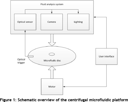
Centrifugal microfluidic systems thus provide many advantages over existing microfluidic technologies, because diverse functionality can be achieved using only a compact motor, compared with a number of other microfluidic platforms that require bulky, costly equipment to manufacture and/or power the systems. An overview of the centrifugal microfluidic platform that will be discussed in this work is shown in Figure 1; it illustrates how a complete test set-up can easily be implemented to analyse the centrifugal microfluidic disc devices. In a final centrifugal microfluidic based product, the fluid analysis sytem could be much simpler - or even obsolete - requiring only a programmable motor to achieve a fully functional system.
1.1 Advantages of centrifugal microfluidics
A number of existing microfluidic technologies and systems require active components such as pumps, actuators, and active valves for successful fluid manipulation. These components are typically costly and complex [4, 6]. The centrifugal microfluidic platform eliminates the need for these kinds of active elements, and gives the platform a competitive advantage over a number of existing microfluidic systems. With only a small motor required to spin the disc device and drive the system, centrifugal microfluidic systems are a particularly attractive solution for implementing a variety of microfluidic operations.
An important benefit of the centrifugal microfluidic platform is the low cost and rapid fabrication techniques that can be used to realise the disc devices. Simple designs manufactured from plastic and adhesive layers can be used to manufacture microfluidic disc devices in-house, rapidly, and at a low cost. Numerous devices can be implemented on one disc as a result of radial symmetry, providing a high throughput of prototype devices for testing.
1.2 Theory of centrifugal microfluidics
A brief overview of the mechanisms employed by centrifugal microfluidic systems is presented in the section below, to understand better how the rotational forces of a simple motor can be used to implement a vast array of fluidic functionality. The primary forces enabling fluidic operations to be achieved are the centrifugal, Coriolis, and capillary forces. A number of detailed reviews of centrifugal microfluidic systems provide theoretical descriptions of the forces and their applications [3-5], and thus only a brief summary with example applications of each force is provided below.
- Centrifugal force: this is the dominating force used to move fluid within microfluidic disc devices in centrifugal microfluidic systems. The centrifugal force causes fluid flow to be directed from the centre of the disc outwards, in a radial direction. This is described mathematically as:
f = -ρω x (ω x r) (1)
where ρ is the mass density of the fluid, ω is the rotational frequency, and r is the radial position along the disc. The centrifugal force is commonly used to pump or move fluid, and to produce sedimentation of particulate fluids or compression of fluids.
- Coriolis force: this secondary force moves in a direction that is perpendicular to the centrifugal force, i.e. in a tangential direction. This is described mathematically as:
f = - 2ρω x 2)
where ρ is the mass density of the fluid, ω is the rotational frequency, and v is the vector of flow velocity. The Coriolis force facilitates the mixing of fluids by alternating the spinning of the disc in clockwise and counter-clockwise directions; it also determines the fluid flow path by directing fluid into either a left or a right fork in a channel.
- Capillary action: this force counteracts the centrifugal force, and can be used to implement valves in centrifugal microfluidic disc devices. When the rotational speed of the disc device is equal to the capillary force, the burst frequency is reached. Once the rotational speed exceeds the capillary force, the valve bursts, releasing the fluid. The capillary force is described mathematically as:
f = 2c/r cos θ (3)
where σ is the surface tension, θ is the contact angle, and r is the radius of the capillary. Capillary action is often used to create valves to release fluids in a timed, controlled manner.
The work presented here details the implementation of the first centrifugal microfluidic platform in South Africa. Initial work has been designed to showcase the platform and test various microfluidic components as the foundation for many future applications. Rapid and low-cost manufacturing techniques can be used to fabricate the centrifugal microfluidic disc devices, enabling a variety of microfluidic operations to be achieved quickly and effectively, and providing an accelerated route to market for such microfluidic devices, particularly for point-of-care diagnostic applications.
2 THE CENTRIFUGAL MICROFLUIDIC PLATFORM
The centrifugal microfluidic platform consists of two main parts: 1) a microfluidic disc device, and 2) a system to control and analyse the fluid flow within the disc device. Both components will be presented here, focusing on the design and manufacture of the microfluidic disc devices.
2.1 Disc design and manufacture
Rapid and low-cost prototyping of centrifugal microfluidic disc devices has been implemented using both two-dimensional and three-dimensional prototyping techniques. The prototyping process involves the design, manufacture, and assembly of microfluidic disc devices. The first step is the design of the device using computer-aided design (CAD) software. An example of a two-dimensional microfluidic disc design is shown in Figure 2. The disc has a radius of 60 mm - the same as a standard CD. Fluidic chambers and channels have been designed to allow for two different fluids to be introduced and combined to be mixed together. It can be seen that four identical fluidic circuits are housed on one disc.

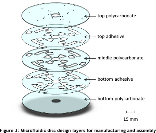
To prepare the design for manufacturing, different layers are created to house the different microfluidic features. For the two-dimensional prototyping technique, layers of plastic and adhesives are machined and assembled to create the complete disc device. Typical disc devices consist of a top, middle, and bottom polycarbonate (PC) layer, made from 1 mm thick polycarbonate sheets (Naxel, Maizey Plastics); layers of 100 pm thick pressure-sensitive adhesive (Flexmount DFM 200 clear V-95 150 Poly H-9 V-95 400 H-9, Flexcon) are used to bond the layers together. Figure 3 illustrates the typical device layers to be manufactured. The top PC layer contains the holes required for fluid introduction and for air vents. The top layer of pressure-sensitive adhesive contains venting channels and fluid chambers. The middle PC layer houses all the fluidic chambers, while the bottom adhesive layer contains the fluidic chamber and channel features. The bottom PC layer forms the base of the device with which all fluid flow makes contact.
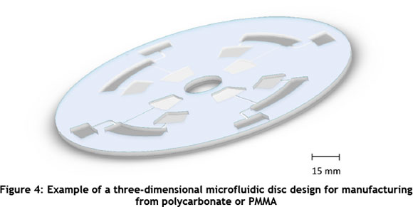
Three-dimensional prototype designs can also be made using different layers extruded to various desired depths and assembled into one device. Either PC or Poly(methyl methacrylate) (PMMA) layers with a thickness of 3-5 mm can be used to manufacture the three-dimensional designs. Figure 4 illustrates a three-dimensional design (similar to the two-dimensional design of Figure 2), with each chamber and channel having a different depth.
To create the complete disc device, an additional polycarbonate layer containing holes for fluid inlets and air vents will be required, as well as one pressure sensitive adhesive layer to bond the top layer to the three-dimensional machined device. Three-dimensional prototyping enables a greater variety and higher degree of control of design dimensions to be achieved, allowing for more precise control over microfluidic operations within the device.
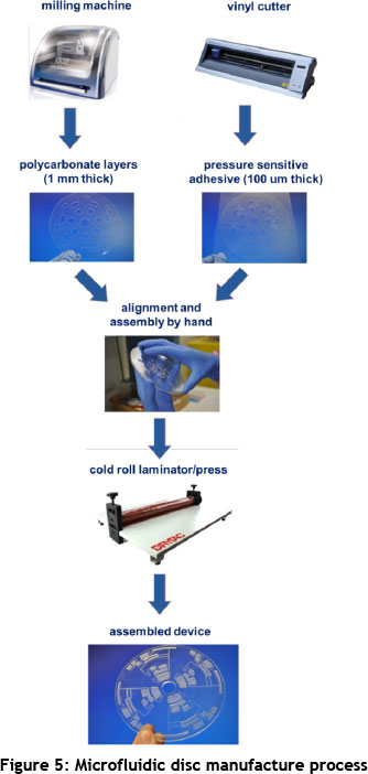
For both the two- and the three-dimensional centrifugal microfluidic device designs, a milling machine (ProtoMat S63, LPKF Laser and Electronics) is used to manufacture the PC or PMMA, while a vinyl cutter (Roland GX-41 CAMM 24" x 12", Telpro Management) is used to machine the desired features of the pressure-sensitive adhesive layers.
The various layers are aligned and pressed together by hand, and permanently bonded using a cold roll laminator (ML25, Drytac) to produce the assembled microfluidic disc device. The centrifugal microfluidic device manufacturing process is shown in Figure 5, illustrating the equipment and materials used in the process, and showing an example of a complete assembled device.
2.2 Fluid control and analysis system
A set-up to test the disc devices and record the results has been implemented and is described in this work. The set-up includes a motor to rotate the disc and a visualisation unit that allows for an image of an area of interest to be captured for each revolution of the disc. Different rotational speeds and timing cycles are used to implement various fluidic operations.
Figure 6 shows the laboratory test set-up used to control and analyse the microfluidic disc devices. A motor rotates the disc at different user-defined speeds to achieve various fluidic operations, while an imaging system consisting of a camera, strobe light, and optical sensing unit enables visualisation and analysis of the fluidic operations on the disc as it spins.
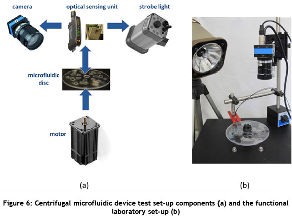
The motor and controller unit used was a Smartmotor SM3450D (Animatics), and the CMOS camera and lens (The Imaging Source) were a DFK 22BUC03 and C1614-M (KP), respectively. The optical sensor and fibre optic cable (Banner) - a D10DPFP and a 0.5 mm fibre plastic, respectively - were used to trigger the camera and the DT-311A Stroboscope strobe light (Shimpo) using a reflective tape on the disc device. This enabled a clear image of the disc device to be captured for each revolution of the disc. The user defines the spin cycles of the disc via a user interface, providing control over the speed, acceleration, deceleration, and timing cycles of the disc, and allowing for automated fluidic operations to be achieved on the disc.
A microscope attachment was also implemented as part of the camera and lens set-up to allow for a magnified view of the fluid flow. This is useful to visualise fluidic operations with fine detail - for example, the droplet generation shown in Figure 9.
3 RESULTS
Preliminary test results show that a variety of microfluidic operations can be achieved, including valving, pumping, and microfluidic droplet generation. Incorporating paper into disc devices was also investigated to achieve further fluidic control within the centrifugal microfluidic device.
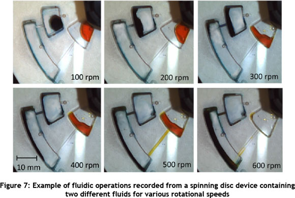
To illustrate valving and pumping of fluids within a centrifugal microfluidic disc device, the disc design shown in Figures 2 and 3 was manufactured, assembled, and tested using two different coloured dyes in de-ionised water. The chambers were designed and manufactured to a depth of 1.2 mm, while the channels had a depth of 100 pm and were 1 mm wide. Figure 7 shows the resulting fluid introduction, valving, movement, and mixing by spinning the disc device at different rotational speeds. Approximately 70 pl of both a yellow dye and a blue dye are introduced into chambers 1 and 2 respectively.
At 100 rpm, no fluid movement is seen, as the centrifugal force is low. At 200 rpm the fluids start to compress in the chambers, and at 300 rpm the blue dye starts to be released from chamber 2. At 400 rpm the blue dye has been released completely from chamber 2 into the mixing chamber. It can be seen that the yellow dye in chamber 1 only starts to be released into the mixing chamber at 500 rpm, as the centrifugal force is much lower towards the centre of the disc than towards the outer circumference for a given rotational speed. This means that a greater rotational speed is required near the centre for the centrifugal force to overcome the capillary forces in order to release the valve. At 600 rpm both dyes have been released completely into the mixing chamber and are mixed as the disc continues to spin. An acceleration of 350 rpm2 was used each time when increasing the rotational speed.
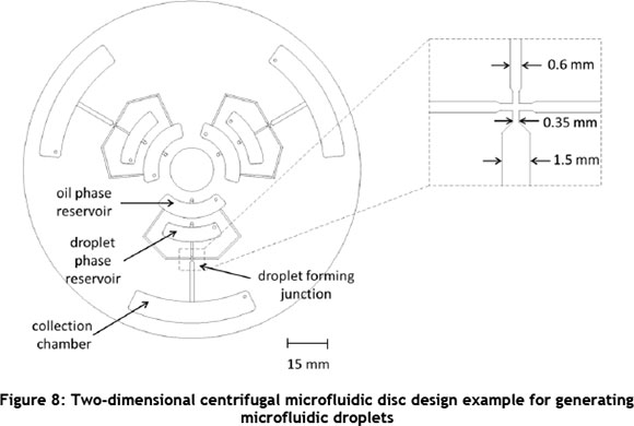
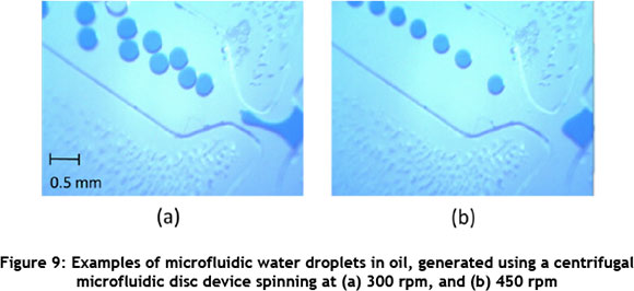
Generating droplets in microfluidic disc devices was also investigated. Microfluidic droplet generation is a vast field of research with numerous applications [7, 8]. Figure 8 shows the microfluidic disc design that was manufactured and tested to allow droplets to be generated (Figure 9). Blue dye in de-ionised water was used as the water or droplet phase, and mineral oil was used as the oil or continuous phase. Approximately 100 pl each of the water and oil phase fluids was introduced into the appropriate chambers or reservoirs, as in Figure 8.
A 4X microscope objective was used to visualise the droplets being generated. At 280 rpm droplets started forming, and stable droplet generation was observed between 300 rpm and 500 rpm, producing droplets of about 350 Mm in diameter. An acceleration of 350 rpm2 was used each time when increasing the rotational speed.
There are limitations to the droplet sizes that can be achieved with the centrifugal microfluidic disc prototyping methods used in this work, as the channel dimensions are only accurate for channel width designs of 300 Mm or more. Alternative prototyping methods ( such as the three-dimensional prototyping method) could improve the resolution of the achievable channel dimensions. Alternatively, microfluidic devices manufactured in the laboratory using soft lithography techniques, and having very fine channel dimensions (as small as 50 Mm), can be mounted into slots on a PMMA disc and actuated, using the centrifugal platform, to achieve smaller droplets.
A centrifugal microfluidic disc design incorporating paper into the disc device was designed, manufactured, and tested to investigate fluidic manipulation by using the opposing forces of the centrifugal force of the spinning disc and the capillary force of the paper.
Paper-based microfluidic systems have recently gained interest as a microfluidic technology for the future [9]. Limited work has been carried out to combine centrifugal and paper-based microfluidics [10], but this emerging field shows promise in achieving greater control and diversity of fluidic operations in centrifugal microfluidic systems.
Figure 10 shows the microfluidic disc design that was manufactured and tested to allow strips of paper, similar in size and shape to lateral flow tests (such as a home pregnancy test), to be incorporated into the microfluidic disc device. The simple design allows a yellow dye in de-ionised water (about 70 Ml) to be introduced into the disc and into a chamber. When the disc starts spinning at a low speed, the valve of the introduction chamber bursts, releasing the fluid into the fluid compression chamber. At higher rotational speeds, the centrifugal force dominates, the fluid is compressed in the chamber, and no fluid is pulled up along the strip of paper. Once the rotational speed is slowed down significantly or stopped, capillary forces dominate, and the fluid is pulled out of the compression chamber and along the strip of paper.
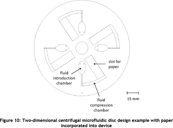
Figure 11 illustrates the flow of fluid for different rotational speeds. At 400 rpm, the fluid is in the process of being released from the introduction chamber into the compression chamber. At 500 rpm all the fluid is dispensed into the compression chamber, and centrifugal forces dominate, compressing the fluid and preventing the fluid from travelling along the paper. When the disc is slowed down to 100 rpm, the centrifugal force is very low, the capillary force of the paper dominates, and the fluid begins to travel along the paper. Keeping the speed at a low 100 rpm enables the fluid to move along the length of the paper completely. An acceleration of 350 rpm2 was used each time when adjusting the rotational speed.
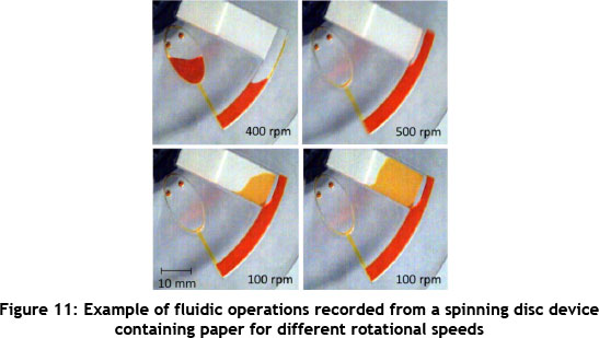
Incorporating paper into the microfluidic disc devices has a number of benefits. Bidirectional flow within the disc device can easily be achieved, as shown in Figure 11, by using both the centrifugal force of the spinning disc and the capillary action of the paper device. This bi-directional flow could also help to mix fluids within a centrifugal disc device. Paper devices can be used to capture an analyte of interest and to visualise it, using a colour change as a result of the capturing process. This eliminates the need for a complex analysis system to be incorporated into the centrifugal microfluidic system, and allows for either a manual visual analysis or a simple automated colour analysis to be used.
4 DISCUSSION
The design, manufacture, and testing of various microfluidic operations have been successfully implemented, illustrating the success of the rapid and low-cost prototyping techniques used to create centrifugal microfluidic disc devices. Both two-dimensional and three-dimensional design and manufacture processes can be implemented to achieve a fully-functional microfluidic disc.
Functionality such as introduction, valving, pumping, and mixing of fluids was successfully showcased (Figure 7). These fluidic operations form the backbone of most microfluidic systems, and have been achieved here using only a motor to spin the disc device. More complex microfluidic operations, such as droplet generation, were also illustrated (Figure 9) with a number of potential applications, including the production of immobilised enzyme particles, which would be relevant in chemical, food, and textile industries. Integration of paper into centrifugal microfluidic disc devices was also demonstrated (Figure 11), providing additional diversity and functionality to the centrifugal microfluidic disc devices.
A test set-up to control and analyse the centrifugal microfluidic disc devices was successfully implemented and automated for high-throughput prototype testing. A simple microscope attachment system was realised as part of the visualisation set-up to enable fine microfluidic design and functionality details to be observed.
In addition to the rapid and low-cost prototyping results of centrifugal microfluidic disc devices shown in this work, the discs are also ideally suited to high-throughput testing as a result of the radial symmetry of the discs. This means that a number of identical tests can be performed on one device; alternatively, a number of different tests can be performed on one device, providing a multiplexed microfluidic system.
4.1 Platform scale-up
Although the centrifugal microfluidic disc devices are only in the prototyping stage, scale-up of the devices and the centrifugal system is an on-going consideration.
Scale-up of the centrifugal microfluidic prototypes into a low-cost and viable microfluidic system shows promise, as the disc devices could be compatible with various existing and commercially-available technologies such as CD/DVD drives and laboratory centrifuges [11]. This potential accelerated route to market is complemented by the fact that centrifugal microfluidic systems are favourable as low-cost, high-throughput, and diverse solutions for achieving integrated microfluidic systems when compared with other microfluidic technologies [6].
Plastic disc devices can be manufactured in high volumes and at a low cost using readily-available fabrication technologies. In addition, the system for controlling and analysing the disc devices could be reduced to a portable system consisting of a compact motor and simple analysis system. This robust system would be suitable for a number of commercial applications for microfluidic systems, and would be useful in rural environments.
5 CONCLUSION
The first centrifugal microfluidic platform in South Africa has been showcased to enable microfluidic operations such as pumps, valves, and other fluidic functions to be achieved, requiring only a small motor to power the system. The compact nature of the set-up - and the fact that numerous devices can be implemented on one disc as a result of radial symmetry - allows for the rapid development of microfluidic prototypes. Potential accelerated routes to market for applications using the centrifugal microfluidic platform have also been illustrated as part of this work, highlighting the advantages of the platform. These points indicate that the centrifugal microfluidic platform has the potential to enable microfluidic technologies to become feasible products - a hurdle that confronts many existing microfluidic platforms. The ability to develop products rapidly, using compact, low-cost implementations, could have great impact in areas such as point-of-care applications, including medical diagnostics. This would be of particular relevance in South Africa's rural and under-resourced settings, where the need for diagnostic solutions at the point-of-care is greatest and has high impact.
REFERENCES
[1] Haeberle, S. & Zengerle, R. 2007. Microfluidic platforms for lab-on-a-chip applications, Lab on a chip, 7(9), pp. 1094-1110. [ Links ]
[2] Mark, D., Haeberle, S., Roth, G., von Stetten, F. & Zengerle, R. 2010. Microfluidic lab-on-a-chip platforms: Requirements, characteristics and applications, Chemical Society Reviews, 39(3), pp. 1153-1182. [ Links ]
[3] Gorkin, R., Park, J., Siegrist, J., Amasia, M., Lee, B.S., Park, J.-M., Kim, J., Hanshin, K., Madou, M. & Cho, Y.-K. 2010. Centrifugal microfluidics for biomedical applications, Lab on a chip, 10(14), pp. 1758-1773. [ Links ]
[4] Madou, M., Zoval, J., Jia, G., Kido, H., Kim, J. & Kim, N. 2006. Lab on a CD, Annual Review of Biomedical Engineering, 8, pp. 601-628. [ Links ]
[5] Ducrée, J., Haeberle, S., Lutz, S., Pausch, S., Stetten, F.V. & Zengerle, R. 2007. The centrifugal microfluidic Bio-Disk platform, Journal of Micromechanics and Microengineering, 17(7), pp. S103-S115. [ Links ]
[6] Sin, M.L., Gao, J., Liao, J.C. & Wong, P.K. 2011. System integration - A major step toward lab on a chip, Journal of Biological Engineering, 5(6), pp. 1-21. [ Links ]
[7] Teh, S.-Y., Lin, R., Hung, L.-H. & Lee, A.P. 2008. Droplet microfluidics, Lab on a Chip, 8(2), pp. 198-220. [ Links ]
[8] Huebner, A., Sharma, S., Srisa-Art, M., Hollfelder, F., Edel, J.B. & DeMello, A.J. 2008. Microdroplets: A sea of applications? Lab on a Chip, 8, pp. 1244-1254. [ Links ]
[9] Martinez, A.W., Phillips, S.T., Whitesides, G.M. & Carrilho, E. 2010. Diagnostics for the developing world: Microfluidic paper-based analytical devices, Analytical Chemistry, 82(1), pp. 3-10. [ Links ]
[10] Godino, N., Comaskey, E., Gorkin III, R. & Ducrée, J. 2012. Centrifugally enhanced paper microfluidics, MEMS 2012, Paris, France, pp. 1017-1020. [ Links ]
[11] Mark, D., von Stetten, F., & Zengerle, R. 2012. Microfluidic apps for off-the-shelf instruments, Lab on a chip, 12(14), pp. 2464-2468. [ Links ]
† This is an extended version of a paper presented at the 14th International RAPDASA conference held at the Central University of Technology in South Africa in 2013.
* Corresponding author

