


Services on Demand
Article
 English (pdf)
 Article in xml format
 Article references
Indicators

Related links
-
 Cited by Google
 -
 Similars in Google
Share

 Permalink
South African Journal of Industrial Engineering
On-line version ISSN 2224-7890
Print version ISSN 1012-277X
S. Afr. J. Ind. Eng. vol.25 n.2 Pretoria Aug. 2014
CASE STUDIES
Functional components produced by multi-jet modelling combined with electroforming and machining
O. BaierI, *; G. WittII
IDepartment of Manufacturing Technology University of Duisburg-Essen, Germany. oliver.baier@uni-due.de
IIDepartment of Manufacturing Technology University of Duisburg-Essen, Germany. gerd.witt@uni-due.de
ABSTRACT
In fuel cell technology, certain components are used that are responsible for guiding liquid media. When these components are produced by conventional manufacturing, there are often sealing issues, and trouble- and maintenance-free deployment cannot be ensured. Against this background, a new process combination has been developed in a joint project between the University of Duisburg-Essen, the Center for Fuel Cell Technology (ZBT), and the company Galvano-T electroplating forming GmbH. The approach is to combine multi-jet modelling (MJM), electroforming and milling in order to produce a defined external geometry. The wax models are generated on copper base plates and copper-coated to a desirable thickness. Following this, the undefined electroplated surfaces are machined to achieve the desired measurement, and the wax is melted out. This paper presents, first, how this process is technically feasible, then describes how the MJM on a 3-D Systems ThermoJet was adapted to stabilise the process.In the AiF-sponsored ZIM project, existing limits and possibilities are shown and different approaches of electroplating are investigated. This paper explores whether or not activation of the wax structure by a conductive initial layer is required. Using the described process chain, different parts were built: a heat exchanger, a vaporiser, and a reformer (in which pellets were integrated in an intermediate step). In addition, multiple-layer parts with different functions were built by repeating the process combination several times.
OPSOMMING
Sekere komponente in brandstofsel tegnologie is nodig vir die lei van vloeistowwe. Daar is dikwels seël probleme wanneer hierdie komponente met konvensionele metodes vervaardig word en probleem- en instandhoudingsvrye ontplooiing kan nie gewaarborg word nie. 'n Nuwe proses kombinasie is ontwikkel in 'n gesamentlike projek tussen die Universiteit van Duisburg-Essen se Sentrum vir Brandstofsel Tegnologie en Galvano-T GmbH, 'n vervaardiger wat van elektrovorming gebruik maak. Die benadering is om multi-straalmodellering te kombineer met elektrovorming en freeswerk om 'n eksterne geometrie te produseer. Die waksmodelle word gegenereer op koper basis plate en word met koper bedek tot op die verlangde dikte. Gevolglik word die elektroplateerde oppervlakke gemasjineer tot op die verlangde afmetings en die waks word weggesmelt. Hierdie artikel beskryf hoe dié proses tegnies uitvoerbaar is, asook hoe die multi-straalmodellering op 'n 3-D Systems ThermoJet aangepas is om die proses te stabiliseer. Bestaande beperkings en moontlikhede word uitgelig en verskillende elektroplateringsbenaderings word ondersoek. Die studie ondersoek ook of die waksstruktuur deur 'n aanvanklike geleidingslaag geaktiveer moet word of nie. Verskillende onderdele van die proses is vervaardig, onder andere 'n hitteruiler, 'n verdamper en 'n hervormer. Daarby is meervoudige laag onderdele met verskillende funksies vervaardig deur die proses verskeie kere te herhaal.
1 INTRODUCTION
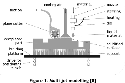
With the increase in different versions of products, individualised production (mass customisation) and small series production (additive manufacturing (AM)) has become increasingly important for product development and the production of component parts. In contrast to conventional manufacturing methods such as milling, turning, or injection moulding, AM technologies build parts layer-by-layer. With the help of a computer-aided design (CAD) model, components can now be produced directly without using tools or moulds [1, 2, 3, 4, 5]. In a survey carried out in 1999, about 40 different AM approaches were identified [6]. For this reason, among other things, the Association of German Engineers created the "VDI Guideline 3404" [5], which lists ten different types of AM technologies. Some material-depositing processes are described in this guideline, in addition to powder-bed based processes such as laser sintering (LS), laser-beam melting, 3D printing, mask sintering, and the liquidbased stereolithography. One example of material-depositing technologies is multi-jet modelling (MJM). With MJM, molten thermoplastic material (e.g., wax) is deposited through droplet-based printing heads. The material melts when heated by the print heads, and hardens on impact [5]. The system used by MJM is the 3-D Systems' ThermoJet, which was introduced in 1999. This system's print head contains 352 nozzles, and the layer thickness amounts to 0.04 mm [7]. A schematic diagram of an MJM is given in Figure 1.
According to the VDI Guideline 3404, there are three different types of process chains for using additive technologies: direct, direct multi-stage, and indirect. If AM is used as a direct or direct multi-stage process, the produced geometry is the final product; while in indirect processes, at least a secondary process is needed. The process chain for indirect processes is shown in Figure 2.

MJM is one of the additive technologies that is used predominantly to produce transfer models for indirect processes such as precision casting [9]. Another application of an indirect process chain was developed at the University of Duisburg-Essen as part of a collaboration between the chair of manufacturing technology, under the leadership of Prof. Witt, the Fuel Cell Research Center Duisburg (ZBT), and the company Galvano-T electroforming plating GmbH. This approach combines the primary process of additive fabrication MJM with the secondary process of electroplating. The difference from previous applications of coating procedures is that the former approaches merely used the combination for finishing surfaces [10]. In this research, electroplating takes a leading part in the manufacturing process. The basic idea emerged in response to sealing issues in fuel cell components. Some of these parts are responsible for guiding liquid media, and are produced by conventional manufacturing. As a result of this conventional manufacturing, a trouble- and maintenance-free deployment cannot be ensured at all times. Currently, two halves of the parts are produced by machining, and then they are screwed together using a sealing cord. Sealing issues arise along this cord, and there are restrictions due to the cord material. This research argues that very thin electroplated coats should be considered in applications of the above technology, because they are impermeable. Section 2 outlines the main concept behind this research.
2 MAIN CONCEPT
The main concept of this project consists of the following five steps:
- Preparing a metal base;
- Generating the wax model;
- Electroplating of the wax-copper part;
- Removal of the wax; and
- A milling process.
These steps are presented in detail, as a circular chain, in Figure 3.
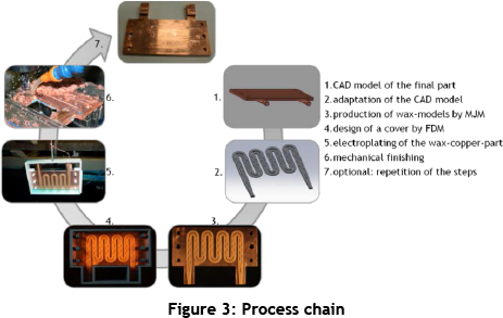
First, a CAD model of the final part is needed. For the production according to the process chain, the model has to be adapted. The AM process produces the inner structures and not the whole part. In the case of an indirect process, according to the VDI Guideline 3404, this part represents the transfer model. Therefore the process chain's capabilities need to be considered when designing the inner geometry. By using the MJM for producing the transfer model, very thin and complex structures are possible. Thin copper sheets, which have cross-sections as close to the end geometry as possible, are used as base plates; this minimises any re-working.
The next step is to design a cover for the electroplating process into which the wax-copper part can be inserted. Here the inner contours are exactly the same as the outer contours of the copper sheet. These covers also help to reduce potential re-work by defining the space into which the material can be electroplated. Currently the covers are manufactured by fused-layer modelling (FLM) - an additive technology defined in the VDI Guideline, and also known as fused-deposition modelling (FDM). For the electroplating process, the construct consisting of the wax-copper part inserted into the cover has to be put into the electrolyte until a sufficient thickness of electroplated copper coating is achieved. As discussed later in this paper, a copper coat of 3.6 mm thickness is needed for a reformer, and 1.5-2 mm thickness is needed for the heat exchanger, depending on the channel structure. To achieve a smooth surface and levelled structures, the final machining has to be performed. Undefined parts, such as junctions, can also get a defined shape in the final milling process. Before machining the part, the wax has to be melted out. If the wax is left in the copper part when the machining is performed, the generation of heat could result in the wax expanding, which could damage the part [11, 12].
2.1 Adaptation of the multi-jet modelling (MJM) for research purposes
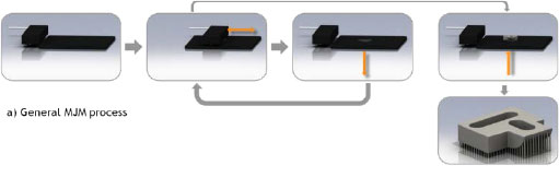
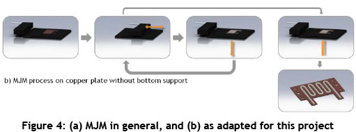
The main difference between MJM in general and its use in this project is the omission of the process-related support structure. ThermoJet's software creates a needle-like structure below overhangs and below the completed part. This structure enables the production of complex designs, and makes it easy to remove the parts from the building platform. The general MJM is depicted in Figure 4a. In order to build parts directly on a copper plate, building supports have to be disabled. By trying to manipulate the software, a function in the maintenance software was detected that enables the choice of an arbitrary start layer. Since the support is built within the first 125 layers, this value must be selected as the start layer. The adapted MJM process is depicted in Figure 4b [11].
Because the support structure is absent and the parts are built directly on a plate, bonding problems can occur. Attempts to pre-treat the copper plates by roughening the surface with blasting, or smoothing it with plasma- or electro-polishing, do not lead to acceptable results. It is more successful if the building process is started on pre-heated copper plates, in combination with a slow cooling down of the wax-copper part after the build process. Experiments with different temperatures indicated that the value of 55°C was best for lasting adhesion. To establish an accurate part height, several attempts were needed to determine the required distance between the nozzles. For the accuracy of the part height, the distance between the nozzles is determined by attempts [11, 12].
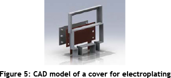
2.2 Cover for defined electroplating
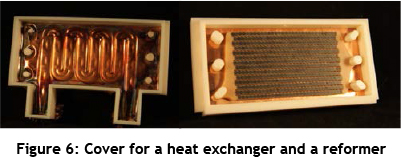
For a near-net-shape production during the electroplating process, covers were designed for the copper-wax parts to be inserted into. For the first tests, square covers were used with square copper plates. The reason for using a cover is to define the deposition. The covers are produced by FLM. For covering the more complex copper plates for the fuel cell components, different designs were tested. Figure 5 shows a CAD model, depicting several parts of a cover for electroplating. Figure 6 shows the covers for the heat exchanger and the reformer.
2.3 Electroplating process
Electroplating is a process for precipitating metallic deposits, and comprises a wide range of deposition processes and materials. This paper will only focus on the electroplating process adopted in the study: the electrochemical direct-current deposition process. In this process, the object to be coated has to be connected to the negative pole of a voltage source, while the electroplating material is connected to the positive pole [13]. Both the object to be coated and the electroplating material have to be immersed in an aqueous electrolyte (Figure 7).
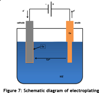
In the above schematic, the object to be coated acts as the negative electrode (cathode), while the copper acts as the positive electrode (anode). The copper electrolyte consists mainly of water, made electrically conductive by electrolytic dissociation of sulphuric acid (H2SO4) and copper sulphate (CuSO4). An electrical field in the electrolyte is established by applying a direct voltage. Thus, positively charged ions (Cu2+, cations) dissolve from the anode by oxidation and move to the cathode. Here they deposit at the surface of the object by reduction. The deposition rate of copper depends, among other things, on the field density at the surface of the parts to be coated [13]. With 350 to 700 µm per day, the exposure rate is relatively low, but the quality of the deposited material is almost as good as that of metallurgical copper. Moreover, the process is automatable. Some basic data of the used copper is explained below [12]:
- Electrical conductivity: 58 MS/m
- Thermal conductivity: 350-400 W/(m*K)
- Hardness: 115 - 120 HV 0,5
- Yield strength Rp0,2: 255-275 N/mm2
- Tensile strength Rm: 330-350 N/mm2
- Elongation A5: 25-30 %
One of the most important advantages of using electroplating for the process chain is the low temperature. The actual electroplating takes place at room temperature, which means that there is no risk of melting the wax too early. Important to note is that the used wax melts at a temperature of approximately 80-90°C [14], and as a consequence, a complete removal is possible at a temperature below 125°C. An appreciable change in copper's physical properties takes place from temperatures of 170°C upwards. Other methods, such as soldering or welding, require far higher temperatures, and affect the material's characteristics. For the application in fuel cell technologies, another peculiarity needs to be mentioned: electroplated coats are impermeable even when they are very thin. In addition, the bond between the base plates and the electroplated copper is leak-proof, even with thin layers. Previous research shows that helium gas leak rates of 1*10-9mbar*l/s at a coating thickness of 300 to 500 µm. This enables part thickness and weight to be reduced by re-designing the fuel cell components built by the process chain [12].
For the electroplating process in this research, the wax-printed copper plates have to be pre-treated. It is necessary to pickle the copper in order to achieve a metallically-clean and oxide-free surface. This step is necessary to ensure adhesive electroplating. The pickling process is ablative, but due to its purely chemical nature, it does not endanger the adhesion between the copper and the wax. Considering the low bond strength between the wax and the copper plates, mechanical cleaning such as blasting, abrasive cleaning powder, or brushing cannot be used. De-greasing is also not feasible because of the low melting point of wax. In order to conserve the wax model and the adhesion, it is better to pre-treat the copper surface as well as possible before printing the model on it. Preliminary tests revealed good results by taking the afore-mentioned approach [12].
Electroplating can begin with a clean surface. The insulating wax has to be taken into account when electroplating wax-copper parts. There are three possible ways to address this:
- Activating the wax structures with a silver spray before starting the electroplating process;
- Starting the electroplating process without activating the wax structure; and
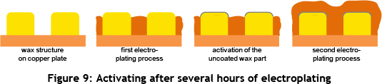
- Starting the electroplating process without activating the wax structure, but activating the wax before it is surrounded by deposited copper
As shown in Figure 8, two different problems are encountered in the first two approaches: (1) Activating the wax structure before electroplating might lead to cavities forming between several of the wax channels; and (2) If the wax structure is not activated, the deposited material might merge above the wax channels, leaving gaps.
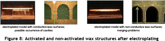
The third approach is the best option. The deposited material should first grow until it reaches a height just below the top of the wax structure; then the wax needs to be activated before continuing the electroplating process. A schematic diagram of the third approach is shown in Figure 9 [11].
The first part of this paper has outlined the best approach for electroplating in this case. Section Three will present an overview of the parts produced in this study, starting with the original geometry of the heat exchangers designed for conventional manufacturing, moving on to the complex micro-heat exchangers, and ending with the reformers with integrated pellets.
3 APPLICATION EXAMPLES
This section provides an overview of the parts produced by applying the new electroplating approach. All of the parts presented in this section are components for fuel cell technology - in particular, parts integrated in fuel cell stacks. The presented components are responsible for guiding different liquid media. Copper is resistant to these fluids, and it is also known to be a very good heat conductor. In combination with the impermeability ensured by using the process chain, the application of such heat exchangers, multiple-layer parts, and reformers may stabilise the fuel cell technology.
3.1 Heat exchanger
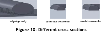
The first part to be produced with the new process combination is a heat exchanger for fuel cell stacks. Considering that the original geometry is designed for conventional manufacturing, it is surprising that it is not applicable to printing on a copper plate. ThermoJet's software would create support structures at the bottom of the elliptical cross-section. Besides, the contact area would be too small, and the wax would come off the copper. Re-designing the cross-section is the only way to solve the problem. Two feasible modifications and the original geometry are depicted in Figure 10. On the left-hand side of Figure 10, the theoretical support structure is shown.
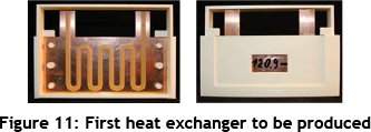
The first samples were produced using the rounded cross-section. The major problem to be solved is the positioning of the copper plate. ThermoJet prints parts in the middle of the building platform. In order to determine the exact position initially, the wax geometry is printed on the regular platform. Marking the endpoints of the structure shows where the copper plate should be placed. Using the parameters mentioned in Section 2.1, the adhesion of the wax does not present a problem. Figure 11 shows one of the first models that was inserted in an early FLM cover.
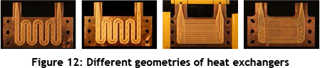
The electroplating process of the depicted geometry can be performed easily. Only the FLM material poses a problem. Due to its porosity, some of the electroplating material grows through, making it harder to ensure a non-destructive removal. The low deposition rate and the new possibilities presented by the process combination make it obvious that the structure to be built should be re-designed. A lower cross-section reduces the required height of electroplating - hence the process time. Reducing the height can lead, however, to decreased cross-sectional areas. Previous volume flows are not within reach, which affects the cooling capacity. Against this background, some new designs have been made for testing the process chain; four of them are shown in Figure 12.
Special attention is devoted to the part height, as mentioned before. Beside the advantage of shorter electroplating processes, the complete height of the component is reduced. In addition, the part weight decreases and less copper is needed, which affects the price. One of the design rules is that the wax surface on top of the part has to be 'interrupted' by gaps. This design rule has various advantages. First, the deposited copper can grow through these gaps; this is important because it ensures that there is equal deposition. Second, the completed parts are stronger because there would be a huge unsupported cavity without the gaps. Attempts to save material by depositing very thin layers on to the wax would result in the destruction of the part because the pressure resistance would be too low.
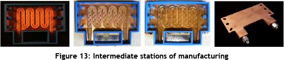
The two different basic forms, shown in Figure 12, were modified to ensure trouble-free electroplating and enable the best performance in the fuel cell stack. In Figure 13, the different intermediate stations are depicted. The first picture shows the wax-copper part inserted in the FLM cover. In the second picture, the part is shown with coating just before growing together above the wax part, and with the wax activated by using silver spray. The third picture shows the complete electroplated structure. On the right-hand side, the finished part is shown. When the first parts were inserted into the fuel cell stacks, good results were found with regard to the stack performance. Good results were also found from the heat exchanger designed for large-scale stacks with a contact area of 200 cm2 instead of the 50 cm2 (as shown Figures 11 to 13).
3.2 Multiple-layer parts
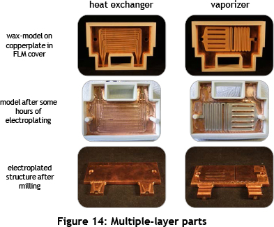
The next step in the project was the production of multiple-layer parts with different functions in every layer. In Figure 14 a two-sided printed copper base is depicted. One side is assembled with the heat exchanger described in Section 3.1. On the other side, a vaporiser was built on to the copper plate. The wax-copper part was inserted into a modified cover without a bottom plate. Thus the electroplating copper could be deposited simultaneously on both sides. The figure shows the part at different points during the manufacturing process. First the wax-copper part in the FLM cover is shown, then the part as it was after several hours of electroplating. At this stage the wax has to be activated. The final two images display the part after machining. It is clear that the vaporiser side of the part is not coated sufficiently. There are lots of gaps, and the areas without wax on their surface have not grown to the required level. As a result, the depicted part has to be electroplated one more time, and another machining step is required. The heat exchanger side has a plane surface, and no gaps can be seen.
To integrate another function into the component shown in Figure 14, an additional wax model has to be built on the machined surface. The surface has to be smooth so that there are no protruding parts; the printing heads might collide with them, possibly damaging the printing heads. Since the resulting order of the functional layers is essential to the function of the complete part, the reformer model has to be built on the heat exchanger's side. As a consequence, part of the junctions has to be removed. The milled material is designed in the CAD model of the reformer, in order to build it on the copper at the same time as the reformer. Section 3.3 discusses the process of building the reformer. A final electroplating and milling step finishes the part with three integrated functions. Merging these three parts together, major weight and space savings are possible. Results on the multiple-layer parts are still awaited.
3.3 Reformer
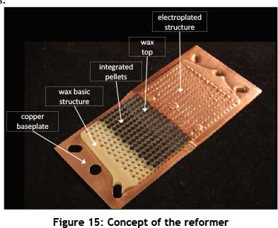
Finally, a reformer with integrated pellets for a chemical process with a fluid flowing around them will be presented. The concept is pictured in Figure 15, showing the arrangement of the single components.
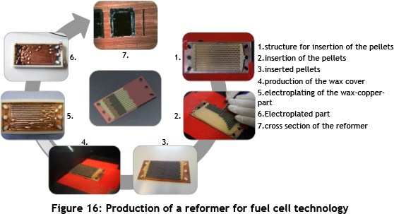
The sequence of production steps is shown in Figure 16. For this process, a similarly-shaped copper plate is required. Initially, the wax structure for inserting the pellets has to be built. In the first attempt, this structure consisted merely of the sidewalls, resulting in problems during the electroplating process. Since the pellets are conductive, they also act as a cathode in contact with the copper plate. Consequently, material deposits on them where the wax cover (described later) is not leak-proof. In a later design, the wax structure has a bottom to isolate the pellets from the copper. Afterwards the pellets have to be inserted into the wax structure. This step is very time-consuming, and there is always the risk of damaging the wax structure. Other solutions have to be found for a potential serial production. This requires that a second MJM process be performed. The pellets need a cover to increase the space fluid's ability to pass through, and to increase the contact area between the pellets and the fluid. The electroplating process can begin once the pellets are inserted into an FLM cover. As with the heat exchanger and the vapouriser, the process has to be stopped before the coating reaches the top of the model. After activating the wax, electroplating can be continued. To finish the part, there needs to be machining and the melting out of the wax. Apart from the low weight and height and the impermeability, the reformer produced by this process chain also has a huge contact area, which increases the effectiveness.
4 CONCLUSION
Different components of fuel cell stacks were produced during this project. A heat exchanger, a reformer, and multiple-layer parts were re-designed with the aim of reducing their height and weight, where possible. The impermeability of the copper coats used in this project stabilised the process in fuel cell technology. The connecting pieces, which presented the only weak spot, have to be re-designed for a series production. The current solution of cutting threads into the electroplated material is leak-proof, but not usable in all applications. The cover design and material need to be improved in further research. As a result of the electroplated copper growing through the FLM material, a non-destructive part removal cannot be ensured. To overcome this problem, and to make the process more efficient, a strategy for the re-use of covers must be found. For a serial production of the reformer, solutions other than inserting pellets need to be found. Differently-conceived geometries may simplify the process. Additionally, other scopes of application need to be considered.
ACKNOWLEDGEMENTS
The ZIM research project is called "Galvanoplastik auf Basis generativ hergestellter Modelle zur Optimierung von Brennstoffzellenkomponenten" (Förderkennzeichen: KF2095007RA9), sponsored by the AIF association of industrial research unions "Otto von Guericke" e.V. (Berlin).
REFERENCES
[1] Lenz, J. 2004. Laser-sintern. Die schluesseltechnologie des e-manufacturing TM. RTeJournal -Forum für Rapid Technologie, Vol. 1. [ Links ]
[2] Witt, G. 2006. Taschenbuch der fertigungstechnik. 1st edition, Munich and Vienna: Carl Hanser Verlag. [ Links ]
[3] Zäh, M.F. 2006. Wirtschaftliche fertigung mit rapid-technologien. 1st edition, Munich and Vienna: Carl Hanser Verlag. [ Links ]
[4] Sehrt, J.T. 2010. Möglichkeiten und grenzen bei der generativen herstellung metallischer bauteile durch das strahlschmelzverfahren. Aachen: Shaker Verlag. [ Links ]
[5] The Association of German Engineers. 2009. VDI Guideline 3404: Additive fabrication - Rapid technologies (rapid prototyping), fundamentals, terms and definitions, quality parameters, supply agreements. Berlin: Beuth Verlag. [ Links ]
[6] Upcraft, S. & Fletcher, R. 2003. Tutorial: The rapid prototyping technologies. Assembly Automation, 24(4), pp. 318-330. [ Links ]
[7] Gibson, I., Rosen, D.W. & Stucker, B. 2010. Additive manufacturing technologies, rapid prototyping to direct digital manufacturing. 1st edition, New York: Springer. [ Links ]
[8] Hoffmann, J. 2000. ThermoJet und medizinische modelle - Ein erfahrungsbericht. RAPROMED 2000. [ Links ]
[9] Wohlers, T. 2009. Wohlers Report 2009: Additive manufacturing and 3-D printing, state of the industry, in Annual Worldwide Progress Report. Fort Collin: Wohlers Associates, Inc. [ Links ]
[10] Wohlers, T. 2011. Wohlers Report 2011: Additive manufacturing and 3-D printing, state of the industry, in Annual Worldwide Progress Report. Fort Collin: Wohlers Associates, Inc. [ Links ]
[11] Baier, O. & Witt, G. 2011. Electroplating of AM wax models for the production of internal structures. Annals of DAAAM for 2011 & Proceedings of the 22nd International DAAAM Symposium, pp. 1163-1164. [ Links ]
[12] Baier, O., Witt, G. & Busch, M. 2011. Generative herstellung von wachsmodellen auf trägerplatten und anschließender galvanoplastischer aufbau zur herstellung komplexer innenstrukturen. RTejournal - Forum für Rapid Technologie, Vol. 8. [ Links ]
[13] Kanani, N. 2009. Galvanotechnik - Grundlagen, verfahren und praxis einer schlüsseltechnologie. 2nd edition, Munich and Vienna: Carl Hanser Verlag. [ Links ]
[14] 3D Systems. 2000. ThermoJet 88 - Material safety data sheet. Retrieved from http://www.3dsystems.ru/global/files/materials/tj88/88MSDS_Eng.PDF. Accessed on 1 May 2012 [ Links ]
* Corresponding author

